Gritco BM-18 Operation instructions

1
Original Manual
Air blast assembly
BM - 18/40/60/100/140/200 - EXC
/VRFTHPc3s
Manufacturer: Official distributor:
Klompenmakerstraat 16d
NL-2984 BB Ridderkerk
the Netherlands
Tel: +31-(0)180-412855
Fax: +31-(0)180-418218
URL: http://www.gritco.com

2

3
TABLE OF CONTENTS
1. PREFACE............................................................................................................... 5
2. SAFETY INSTRUCTION ........................................................................................ 5
3. INTRODUCTION / DATA........................................................................................ 6
Theory ..................................................................................................................... 7
4. DESCRIPTION ....................................................................................................... 8
Overview of the machine ......................................................................................... 8
5. INSTALLING......................................................................................................... 13
6. OPERATION ........................................................................................................ 14
Metering the amount of blast media ...................................................................... 15
Emergency stop..................................................................................................... 15
7. TRANSPORT AND STORAGE ............................................................................ 16
8. MAINTENANCE CHECKLIST .............................................................................. 17
9. TROUBLESHOOTING.......................................................................................... 18
10. EXECUTING REPAIRS / MAINTENANCE ......................................................... 20
11. STOCK ............................................................................................................... 22
12. DRAWINGS........................................................................................................ 22

4

5
1. PREFACE
This manual is to be read by the operator(s) and maintenance people. Both should
have knowledge and skills considering blasting systems.
Failure to properly use of this machine could result in severe injuries or death.
Read this manual first before operating the machine.
Keep this manual in a safe place for future reference and spare part orders.
2. SAFETY INSTRUCTION
Always respect local regulations regarding installation and use of the machine.
Used blast media should be disposed according the local regulations
Be aware that blasting activities can result in static electricity and/or sparks.
Consult local authorities or your supplier for suitable measures too avoid any risks!
The use of the machines is only allowed with:
-suitable non-bleeding positive deadman handle or remote control system
-suitable blast hose and blast hose couplings
-suitable nozzle
Contact your supplier or the manufacturer for detailed info.
Only use original parts for maintenance and repair.
Only use accepted blasting media. Never use blast media containing free silica!
Never direct the installed blasthose and nozzle towards yourself or others.
Never perform any maintenance or disconnect hoses when the machine is in use.
The sound level is determined by blasting pressure, nozzle orifice and (amount of) blasting
media. The sound level at the nozzle can be between 100 - 125 dB. The sound level at the
operator and the machine itself will be lower.
Furnish the operator(s) with approved:
- helmet or mask,
- respiratory equipment,
- protective clothing,
- safety shoes or boots,
- gloves,
- ear protection
Also warn and/or protect people nearby the blasting process with the above items.

6
3. INTRODUCTION / DATA
This machine is for surface treatment purposes like: cleaning, paint and/or rust removal,
surface roughening, surface embellishing etc.
This is done by directing blasting media with compressed air through a hose and nozzle onto
the surface. The impact of the blast media onto the surface results in physically removing dirt
or paint or the distortion of the surface.
Dimensions (mm): model 18: 560 x 460 x 790 model 100: 800 x 700 x 1130
(l x w x h)model 40: 570 x 560 x 920 model 140: 870 x 840 x 1250
model 60: 700 x 510 x 1060 model 200: 870 x 840 x 1440
Vessel contents: model 18: 18 litres model 100: 100 litres
model 40: 40 litres model 140: 140 litres
model 60: 60 litres model 200: 200 litres
Weight: model 18: 45 kg model 100: 110 kg
model 40: 55 kg model 140: 150 kg
model 60: 80 kg model 200: 170 kg
For all models: Maximum system pressure: 10 bar
Minimum system pressure: 5 bar
Maximum compressed air temperature: 50 °C
Minimum compressed air temperature: 5 °C
Maximum ambient temperature: 50 °C
Minimum ambient temperature: 5 °C
Maximum pressure changes
ΔP bar 18 litre 40 litre 60 litre 100 litre 140 litre 200 litre
0 – 6 – 0 790.500 707.330 489.310 211.510 298.410 298.410
0 – 8 – 0 391.100 365.230 206.290 89.274 143.200 143.200
0 – 10 – 0 226.500 215.410 105.750 45.723 75.043 75.043
Coupling connections: Compressed air: Claw coupling acc. DIN 3481/3489
Remote control hose: Quick coupling acc. DN 7,2 / DN 5
Blast hose: European standard
beware that the used
compressor does not
exceed this value!

7
Make sure the compressor has the right capacity to ‘feed’ the chosen nozzle and wanted
blasting pressure.
The compressed air consumption of the machine is determined by the blasting pressure and
the used nozzle orifice diameter:
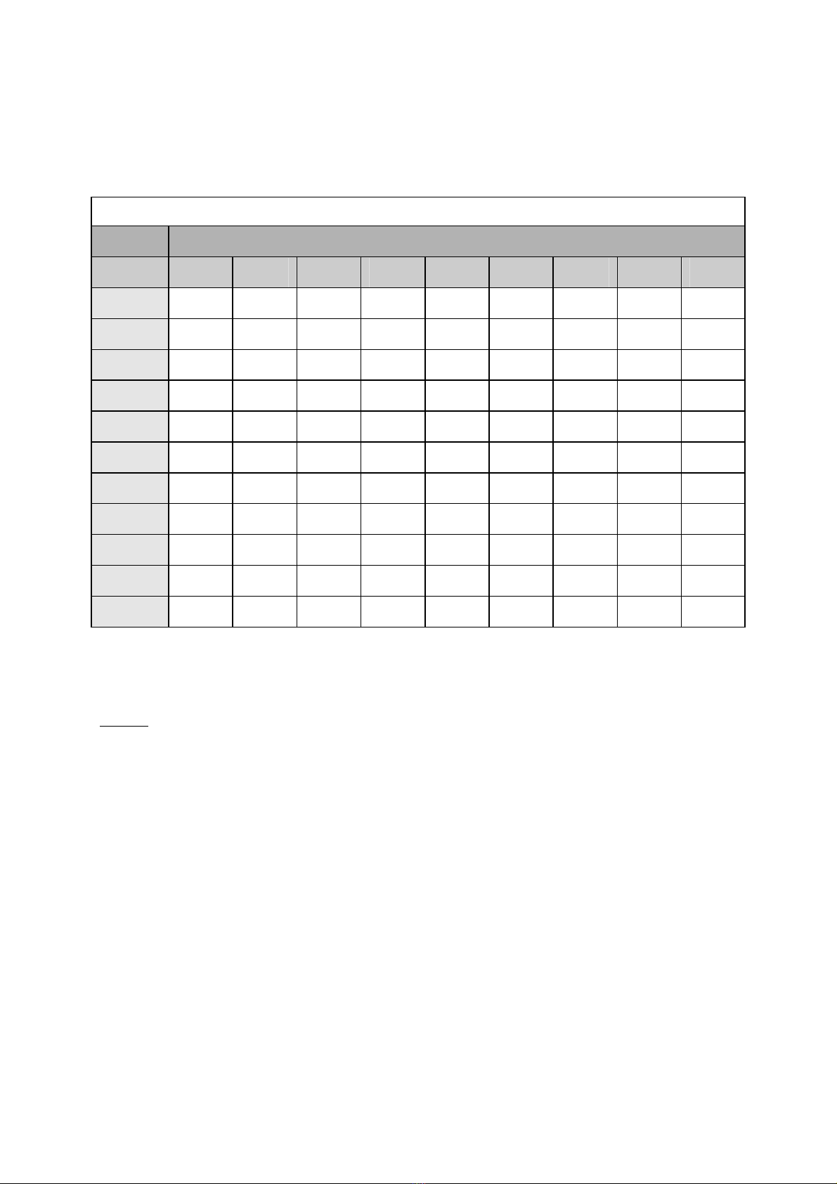
Compressed air consumption in m³/minute
Diameter Blasting pressure in bar
mm 2 3 4 5 6 7 8 9 10
3 0,08 0,25 0,33 0,42 0,50 0,58 0,66 0,75 0,83
4 0,30 0,44 0,59 0,74 0,89 1,03 1,18 1,33 1,48
5 0,46 0,69 0,92 1,15 1,38 1,62 1,85 2,08 2,31
6 0,66 1,00 1,33 1,66 1,99 2,33 2,66 2,99 3,32
7 0,90 1,36 1,81 2,26 2,71 3,17 3,62 4,07 4,52
8 1,18 1,77 2,36 2,95 3,55 4,14 4,73 5,32 5,91
9 1,50 2,24 2,99 3,74 4,49 5,23 5,98 6,73 7,48
10 1,85 2,77 3,69 4,62 5,54 6,46 7,39 8,31 9,23
11 2,23 3,35 4,47 5,59 6,70 7,82 8,94 10,05 11,17
12 2,66 3,99 5,32 6,65 7,98 9,31 10,64 11,96 13,29
13 3,12 4,68 6,24 7,80 9,36 10,92 12,48 14,04 15,60
For data on other nozzles or pressures please contact your supplier or the manufacturer.
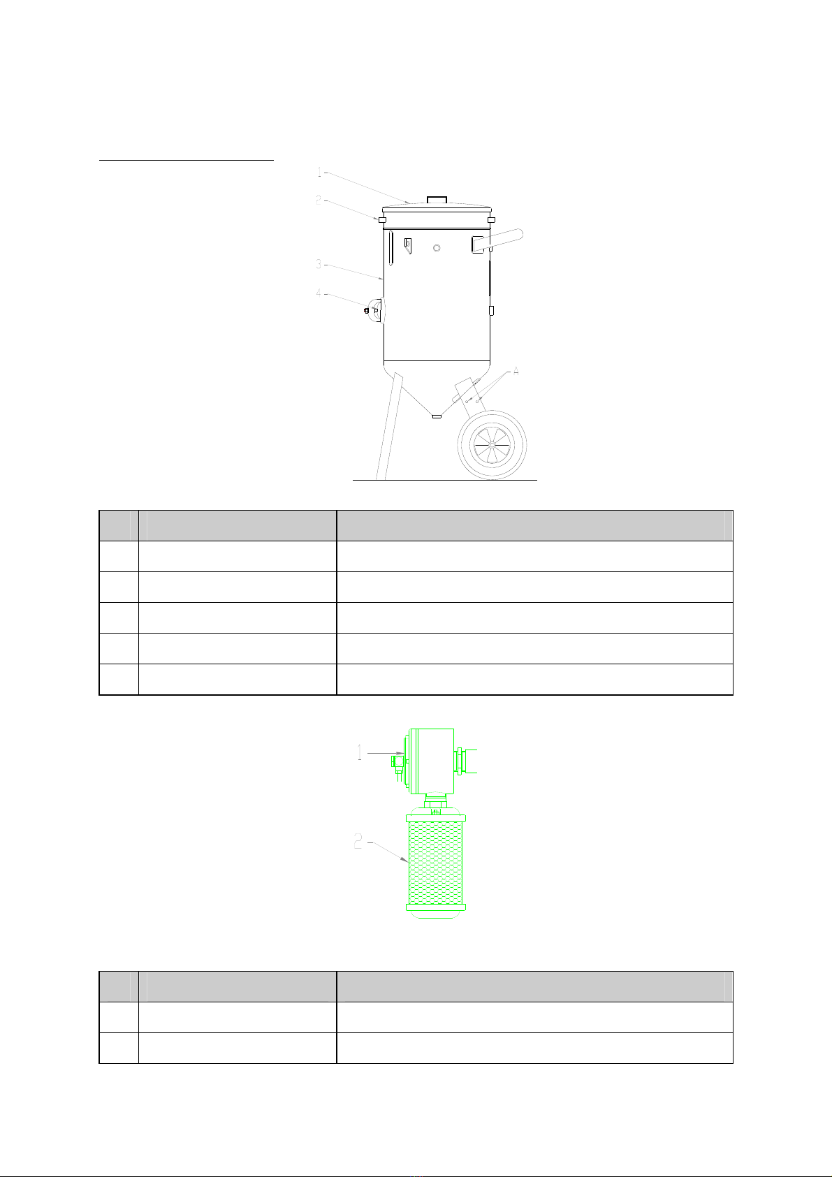
Theory:
The pot of the machine is filled with blasting media and then pressurised. When the machine
is started an air flow with the same pressure starts flowing underneath the pot through the
blast hose to the nozzle Because pot pressure and transportation air pressure are the same, the
blasting media can fall freely inside the transportation air and is directed onto the surface.

8
4. DESCRIPTION
Overview of the machine:
# Item description Function
01 Cover (option) Avoids foreign objects entering the pot.
02 Sieve (option) Avoids too big particles entering the pot.
03 Vessel Contains the blast media
04 Inspection hatch To check the inside of the pot for maintenance purposes.
A Quick couplings Connects the machine to the control hoses
# Item description Function
01 Decompression valve Depressurises the tank (filling, stopping).
02 Silencer Silences the decompression of the tank.

9
# Item description Function
01 Main air valve Controlled by the control system to start and stop blasting.
Pressurising the vessel and start/stop of transportation air flow.
02 Pressure gauge (option R) Indicates the set pressure by the pressure reducer.
03 Pressure reducer (option R) To set the wanted blasting pressure.
04 Compressed air filter (option F) Takes out last bits of dirt and moisture from the compressed air.
05 System ball valve Pressurises the machine.
06 Choke valve Shuts of transportation air (no blasting pressure) for ‘pushing’
small blockages through the abrasive metering valve.
07 Safety valve Avoids a too high pressure of the tank (10 bar)
08 Gauge system pressure Indicates the system pressure (from compressor).
09 Helmet air filter (option H) Removes the oil odour from the compressed air.
A Claw coupling Connects the machine to the compressed air line.

10
# Item description Function
01 Coupling To release the metering valve from the machine’s vessel.
02 Housing Connects vessel, metering valve and mixing tube together
03 Media metering valve PU 12 Opens and closes by signal of the deadman handle or controlsystem
to start and stop the flow of abrasive from the pot. Also to set the
amount of media.
04 Coupling To release the metering valve from the machine’s piping.
05 Mixing tube Where abrasive and transportation air are mixed.
A Blast hose coupling Connects the machine to the blast hose of the hose package.
# Item description Function
01 Ball vibrator (option T) Keeps the abrasive in motion for better flow (especially with very
fine angular and/or hygroscopic material.
02 Pressure reducer (option T) Sets the maximum pressure of the ball vibrator
03 Ball valve (option T) To start/stop an regulate the ball vibrator

11
Inside the pot:
# Item description Function
1 Pop-up protection cover Avoids foreign objects to get stuck between pop-up and pop-up ring.
2 Flange Holds the pop-up ring.
3 Pop-up ring Closes the pot together with the pop-up.
4 Pop-up Comes up and closes the pot together with the pop-up ring.
5 Guidance pipe Guides the pop-up up to the pop-up ring through the compressed air
flow and then fills the pot with this compressed air.
Inside the pot option “V”
# Item description Function
1 Pop-up hood Leafs enough space for the pop-up to come up when the blastpot is
placed under a silo.
2 Pop-up ring Closes the pot together with the pop-up.
3 Pop-up Comes up and closes the pot together with the pop-up ring.
4 Guidance pipe Guides the pop-up up to the pop-up ring through the compressed air
flow and then fills the pot with this compressed air.

12
Example of recommended hose package with deadman handle and nozzle (not included):
# Item description Function
1 Blast nozzle Directs the media onto the surface.
2 Nozzle holder Connects the nozzle to the blast hose.
3 Deadman handle Controls the operation of the machine (start and stop).
Opening / closing of main air valve and metering valve.
4 (Remote) control hose Directs the control/signal air between machine - deadman handle -
machine
5 Blast hose Directs the media and transportation air flow to the nozzle
6 Blast hose coupling Connects the blast hose to the machine.
7 Quick coupling Connects the control hose to the machine (signal from machine)
8 Insert nipple Connects the control hose to the machine (signal to machine)

13
5. INSTALLING
Use the drawings from chapter 4 when reading these instructions.
The machine should be installed according local regulations. Local legislation might oblige to
have the installation approved by a notified body before first use.
Make sure the machine is installed on a straight and steady surface.
Take the machine’s weight for account but also that of the blasting media and operator.
Make sure the machine cannot move during operation.
Don’t expose the machine to water and/or moist because this makes the blasting media clog
making it impossible to work with the machine.
For problem free operation of the machine, dry and clean compressed air is required.
An after cooler with separator (and filters) is necessary. In a fixed execution this can be
extended with a dryer and air receiver.
Connect a compressed air hose to the machine. Consult your supplier for the right size.
Make sure the compressor’s pressure does not exceed 10 bar!
Connect the blast hose from to the machine.
Connect the control hoses from an approved deadman handle or remote control system to the
machine.
Make sure that all hoses are in good condition and secured in their respective couplings.
Refrain from unnecessary curves of the hoses and tension on the machine.
The blast hose should be laid out in a straight line or big radius curves to avoid quick wear.

14
6. OPERATION
Before operating the machine the first time follow all points of this chapter but without the
use of blasting media.
Use the drawings from chapter 4 when reading these instructions.
Fill the machine with dry and clean blasting media.
Optional: Use the sieve when filling and put on the cover before start up
Make sure nothing unusual is situated between the pop-up and the closing ring.
Make sure the system ball valve is closed.
Pressurise the machine by starting the compressor or opening the ball valve between the
compressor and the machine.
Now open the system ball valve. The system pressure is indicated on the gauge.
This pressure will be on/about the blasting pressure.
Optional: Set the wanted blasting pressure with the pressure reducer. Turning clockwise will
increase the pressure, turning it anti-clockwise will decrease the pressure. The set pressure
can read of the gauge. Minimum blasting pressure is about 1,5 bar.
Optional: Start the ball vibrator by completely opening the ball valve. Then slowly close it
until a soft vibrating is reached. Do not change the setting of the ball vibrator’s pressure
reducer.
The machine is now stand-by for operation.
Firmly hold or fix the end of the installed blast hose and direct the nozzle on the to be treated
surface.
Start the machine with the installed deadman handle or the remote control system.
The main air valve is opened and the decompression valve is closed.
Compressed air flows to the pop-up valve. The pop-up will close the pot.
Pressure builds up in the pot.
The compressed air also flows to the blast hose and nozzle (transportation air).
The metering valve is opened as well, so the blasting media can fall into the transportation air
and is carried along.

15
Metering the amount of blast media:
Setting the amount of metering can best be done with two people. One holding the hose
package and nozzle, the other operating the abrasive metering valve.
Start with the metering valve completely closed. Slowly open by turning the knob anti-
clockwise. Stop opening the valve when a constant and regular flow of abrasive out of the
installed nozzle is created.
Too much media will lead to an irregular flow and will not increase the production!
Keep the installed nozzle at an angle and distance so the biggest area is covered and still
cleaned sufficiently. Move the nozzle in the direction in which it is pointed and work towards
the ‘dirty’ area.
Stop blasting with the deadman handle or the remote control system.
The control air signal to the machine will decompress and main air valve and media metering
valve will close (assisted by their springs) and the decompression valve will open.
Hold the installed hose package firmly until all air has released the blast hose.
The pot will decompress and the pop-up falls down.
Refilling
The machine can now be refilled
Blasting activities can be restarted with the deadman handle or the remote control system.
The amount of media does not have to be set again.
Stopping
The blasted objects can be blown off with air only. Close the media metering valve with the
red handle of the optional PL36 or by closing the ball valve of the optional “third signal” on
the machine or installed hose package.
Resume the blasting activities. Because the signal air to the media metering valve is now shut
off, it will not open. Only air comes out of the nozzle so the blasted objects can be air washed.
To stop working shut off the compressor or close the ball valve in the supply line.
If the machine has to be transported or the airline disconnected make sure the machine and
the air supply line are being depressurised.
Wait until all air has been released and the system pressure gauge indicates “0” before
disconnecting any of the hoses!
Emergency stop:
In case of an emergency close the system ball valve. Blasting activities will stop and the pot
will depressurize.

16
7. TRANSPORT AND STORAGE
Store the machine empty.
Store the machine in a dry place.
Only transport when the machine is empty.
Never move the machine when it’s in use.
Never move the machine with attached any hoses.
Always lift or transport the machine with the wheels facing downwards.
The machine can be lifted at the handle bar. If the machine is executed with lifting brackets
these must be used.
The machine can be transported by putting one foot on the axle and tilting the machine with
the handlebar onto the two wheels.
Do not tilt the machine too far to avoid a sudden extra load for the mover.
Place one foot on the axle and put back the machine gently on front leg and wheels.

17
8. MAINTENANCE CHECKLIST
Before performing the next points, always depressurise the machine and air supply line first
and keep the system ball valve closed. Use chapter 10 for executing repair / maintenance.
Check before every use the machine on damage.
Check before every us the condition and function of the installed deadman handle or remote
control system.
Check after every use the silencer of the decompression valve and clean it.
Check every 50 hours the wear of the membrane of the decompression valve.
Check every 100 hours the quality of the couplings and their gaskets.
Check every 500 hours the main air valve.
Clean all parts of the media metering valve every 750 hours.
Check all parts of the optional pressure reducer every 750 hours.
Check and clean all parts of the optional compressed air filter every 750 hours.
Replace the filter cartridge of the option helmet air filter every 1500 hours.
The next points should be checked when the machine is pressurised and in operation by some
else than the operator. Wear approved protective items
Check every 250 hours the functioning of the pressure gauge(s).
Check every 250 hours the machine for leakages.
Check every 250 hours the closing of the pot at the pop-up and pop-up ring.
The machine should be periodically checked according local regulations.

18
9. TROUBLESHOOTING
The machine doesn’t react when starting up.
There is no signal to the machine.
Check the installed remote control system.
The main air valve doesn’t function.
Check the membrane and replace it if necessary.
The membrane of the decompression valve has worn out.
Check the membrane and replace it if necessary.
The machine decompresses slower then before.
The silencer is dirty.
Remove the silencer and clean or replace.
The machine keeps on blasting after stopping with the installed remote control system.
The membrane of the decompression valve has a hole in it (wear).
Replace the membrane.
The main air valve doesn’t close.
The valve disc, O-ring or spring of the main air valve are worn out / broken.
Check and replace if necessary.
Something is blocking the closing of the valve.
Check and clean the inlet and outlet side.
The signal to the machine is not decompressed.
Check the couplings and hose of the remote control systems.
Problems with setting the right pressure of the optional pressure reducer or air keeps leaking
from the reducer.
The reducer is probably dirty.
Clean the interior.
The pressure keeps on dropping during blasting.
The capacity of the compressor is too small.
Set a lower a pressure with the optional pressure reducer or use a
smaller nozzle and check if this is possible.

19
The automatic drain of the optional compressed air filter doesn’t function well
There’s probably a blockage.
Clean the bowl and drain.
Not enough abrasive flows out of the nozzle or nothing at all.
No signal to the abrasive metering valve.
Check the installed remote control system.
Check if the optional “3rd signal” on the hose package is opened.
If the compressor’s capacity is too small for the chosen
blastpressure/nozzle the system pressure will drop. Check if during blasting
the system pressure gauge remains above 5 bar. This is the minimum
pressure required to open the metering valve against the spring’s tension.
The abrasive metering valve doesn’t open.
Check the parts of the valve on damages / wear.
There is a blockage.
Close and open the choke valve 3-4 times quickly during blasting. The pot
will be in a ‘over-pressure’ and small blockages will be pumped through the
orifice of the media metering valve.
There is a blockage too big to be pumped through.
Open the metering valve completely by turning the knob anti clockwise.
When the blockage is gone put the valve back to its former setting.
There is a big blockage in the mixing tube of the metering valve.
Take off mixing tube and check whether it’s dirty.
There is a big blockage at the bottom of the pot.
Remove the metering valve and clean the outlet at the bottom.
If clean abrasive is refilled and no blockage found it is still possible that the abrasive flow is
irregular or doesn't come at all. This is pointing at an over-pressure of the transportation air
that is caused by leakage at the pot of the machine.
First check if the decompression valve is completely closed. This is best done by a second
person. Remove the silencer and check if no air come out during blasting. Wear protective
items! If air comes out check the valve and the membrane.
If this is OK check the following connections very carefully with soap-suds, when the
machine is working.
1. Pop-up ring - pop-up.
2. Pot - abrasive metering housing.
3. Pot - decompression valve.
4. The piping to the guiding pipe.
5. The gasket of the inspection hatch.
6. Diaphragm of the decompression valve.
If after following these points problems still occur, please contact your supplier or the
manufacturer.

20
10. EXECUTING REPAIRS / MAINTENANCE
Before performing next points, always depressurise the machine and air supply line first and
keep the system ball valve closed.
To make the repairs / maintenance easier it is recommended to take the parts from the vessel
so they can be put in a vice.
To remove the media metering valve assembly the couplings both have to be loosened.
The piping of the blastpot can be removed by loosening the coupling as well as the two bolts
of the clamp.
The coloured control hoses can be taken out of their couplings by first pressing the hose
towards the coupling, then hold the black ring of the coupling and pull out the hose.
It is advised to use the required drawings from chapter 12 when executing following repairs /
maintenance.
Main air valve AP 100/112
Replace / check the membrane:
- Remove the four bolts and nuts of the cap.
- Loosen the nut on the shaft. Hold the shaft with a screwdriver.
- Remove the membrane together with the upper and lower membrane plate.
- Take the two plates from each other and place a new membrane.
- When putting everything back make sure the spring is situated over the nut.
Replace the valve disc and/or O-ring:
- Remove the cap and membrane as above
- The retainer bushing is visible now.
- With a screwdriver and hammer the bushing can be loosened
- Remove the retainer bushing.
- Shaft and valve disc can be taken out. Replace the valve disc and/or O-ring.
- When putting everything back make sure the spring is situated over the nut.
Special tools can be ordered to ease the loosening of the bushing. Contact your supplier or the
manufacturer.
Decompression valve PM35/PU 34
Replace the membrane and/or rubber wear disc:
- Remove the six internal wrenching bolts of the cover.
- Replace the diaphragm and or rubber wear disc
- Place the cover back with the six bolts.
This manual suits for next models
5
Table of contents