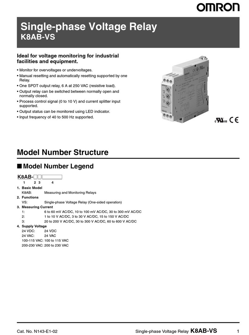
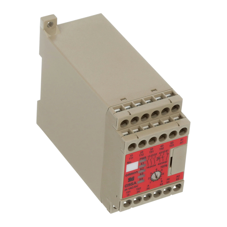
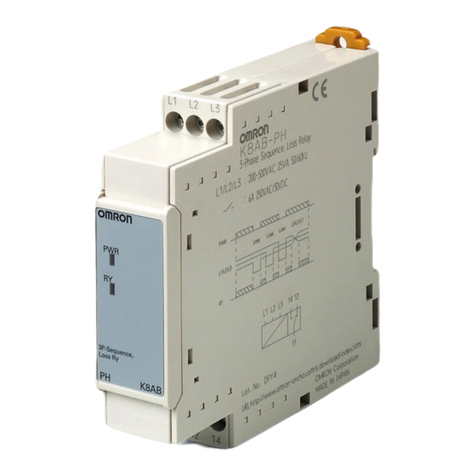
Omron G70D B7A Series User manual

44
Link Terminals with 16 Relay Outputs G70D-B7A
Ultra Miniature Link Terminal with B7A
Communications Functions and 16
Output Points
Equipped
with B7A communications functions
and
enables wiring reductions in B7A connections
(except for high-speed models).
Power relay (G6D) models and power MOS FET
relay (G3DZ) models available.
Compact
dimensions: 156
×
51
×
51 mm (W
×
D
×
H).
The
load is connected directly to the terminal block
without the need for a relay terminal.
Signal status can be confirmed at a glance with
operation indicators.
Incorporates surge absorbing diode.
Equipped with Relay Removal Tool.
Supports either screw mounting or DIN track
mounting.
Ordering Information
Product List
Classification Number of I/O
points
Rated voltage
I/O delay time
Error processing
Model
Relay output
16 (SPST
-NO ×
16)
24 VDC
Normal (typical:
19 2 )
HOLD (See note 2.)
G70D-R6R11-B7A
eayou u
6(S S
O
6)
C
oa(yca
19.2 ms)
(See note 1.)
LOAD OFF (See note
3.) G70D-R6R31-B7A
Power MOS FET
ltt
HOLD (See note 2.)
G70D-R6M11-B7A
oe OS
relay output
LOAD OFF (See note
3.) G70D-R6M31-B7A
Note: 1.
Not connectable to high-speed B7A models.
2.
When an error occurs, the status of outputs just before the error occurred is maintained.
3.
When an error occurs, all the outputs are turned OFF
.
Specifications
Characteristics
Communications Specifications
Communications
method
Unidirectional, time-division
multiplex
T
ransmission distance
(see note)
500 m max.
I/O delay time
T
ypical: 19.2 ms; 31 ms max.
Note: Separate power supplies are required for inputs and out-
puts.

G70D-B7A G70D-B7A
45
General
G70D-R6Rj1-B7A
(Relay Outputs)
Item Specification
Contacts
16 SPST
-NO contacts
Contact mechanism
Single
Contact material
Agco
Contact resistance (See note 1.)
100 m
Ω
max.
Operating time
10 ms max.
Release time
10 ms max.
Maximum switching frequency
Mechanical
18,000 operations/hour
a u s c g eque cy
Rated load
1,800 operations/hour
Insulation resistance
100 M
Ω
min. (500 V)
Dielectric strength
1,000 V
AC, 1 min between each terminal and external parts
Noise immunity
Power supply normal:
600 V
, 10 min; pulse width: 100 ns to 1
µs
Power supply common:
1.5 kV
, 10 min; pulse width: 100 ns to 1
µs
T
ransmission path wrapping:
1.5 kV
, 10 min; pulse width: 100 ns to 1
µs
Link T
erminal wrapping:
600 V
, 10 min; pulse width: 100 ns to 1
µs
V
ibration resistance
Destruction
10 to 55 Hz, 1.0-mm double amplitude for 2 hours each in X, Y
, and Z
directions
Malfunction
10 to 55 Hz, 0.75-mm double amplitude for 2 hours each in X, Y
, and Z
directions
Shock resistance
Destruction
300 m/s
2
Soc essace
Malfunction
100 m/s
2
Operating voltage range
24 VDC +10%/–15%
Current consumption (See note 2.)
24 VDC, approx. 300 mA
Cable length (between Unit and connected device)
Depends on the load
Color of indicators
Operation indicator: orange
Power supply indicator: green (red for errors)
Coil surge suppressor
Diode (400 V
, 300 mA)
Ambient temperature
Operating:
0 to 55
°C
Storage:
–20 to 65
°C
Ambient humidity
Operating: 35% to 85%
Mounting strength
No damage when 49-N pull is applied for 1 s each in all directions (only 9.8-N
pull in direction of DIN track)
T
erminal strength
T
ightening strength: 0.78 to 0.98 N
⋅m
T
ensile strength: 49 N for 1 minute
Weight
Approx. 230 g
Note: 1.
The values above are for the T
erminal in its initial state.
2.
The contact resistance given is for 1 A at 5 VDC.
3. The
value given for current consumption is for when all points are ON and includes the relay coil current for the G6D. It does not
include
the current for external loads or error output.

G70D-B7A G70D-B7A
46
G70D-R6Mj1-B7A (Power MOS FET Relay Outputs)
Item Specification
Contacts
16 SPST
-NO contacts
Isolation method
Photocoupler
Operating time
6 ms max.
Release time
10 ms max.
Output ON resistance
2.4
Ω
max.
Current leakage when the relay is closed
10
µ
A max. (at 125 VDC)
Insulation resistance
100 M
Ω
min. (500 V)
Dielectric strength
1,000 V
AC, 1 min between each terminal and external parts
Noise immunity
Power supply normal:
600 V
, 10 min; pulse width: 100 ns to 1
µs
Power supply common:
1.5 kV
, 10 min; pulse width: 100 ns to 1
µs
T
ransmission path wrapping:
1.5 kV
, 10 min; pulse width: 100 ns to 1
µs
Link T
erminal wrapping:
600 V
, 10 min; pulse width: 100 ns to 1
µs
V
ibration resistance
Destruction
10 to 55 Hz, 1.0-mm double amplitude for 2 hours each in X, Y
, and Z
directions
Malfunction
10 to 55 Hz, 0.75-mm double amplitude for 2 hours each in X, Y
, and Z
directions
Shock resistance
Destruction
300 m/s
2
Soc essace
Malfunction
100 m/s
2
Operating voltage range
24 VDC +10%/–15%
Current consumption (See note.)
24 VDC, approx. 300 mA
Cable length (between Unit and connected device)
Depends on the load
Color of indicators
Operation indicator: orange
Power supply indicator: green (red for errors)
Coil surge suppressor
Diode (400 V
, 300 mA)
Ambient temperature
Operating:
0 to 55
°C
Storage:
–20 to 65
°C
Ambient humidity
Operating: 35% to 85%
Mounting strength
No damage when 49-N pull is applied for 1 s each in all directions (only 9.8-N
pull in direction of DIN track)
T
erminal strength
T
ightening strength: 0.78 to 0.98 N
⋅m
T
ensile strength: 49 N for 1 minute
Weight
Approx. 230 g
Note: 1.
The values above are for the T
erminal in its initial state.
2. The
value given for current consumption is for when all points are ON and includes the
input current for the G3DZ. It does not include
the
current for external loads or error output.
Ratings
Relay Specifications
The
following specifications are for the G6D when it is mounted on the G70D. They are not the specifications for the G6D by itself.
Coil Ratings (for each G6D Relay)
Rated voltage
Rated current
Coil resistance
Must-operate
voltage Must-release
voltage Maximum
allowable
voltage
Power
consumption
24 VDC
10.5 mA
2,880
Ω
70% max.
(See note 1.)
10% min.
130%
Approx. 200 mW
Note: 1.
The must-operate voltage is 70% max. if the Relay is mounted upside down.
2.
The values for rated current and coil resistance are for a coil temperature of 23
°
C with a tolerance of
±10%.
3.
The values for operating characteristics are for a coil temperature of 23
°C.
4. The
maximum allowable voltage is the maximum value of the allowable voltage range for the relay coil operating power supply
.
It
does
not apply in the case of continuous voltages.
5.
The rated current includes the Link T
erminal’
s rated current.

G70D-B7A G70D-B7A
47
Contact Ratings (for each G6D Relay)
Load Resistive load (cosφ
= 1)
Rated load
250 V
AC 3 A, 30 VDC 3 A
Rated carry current
3 A
Maximum switching voltage
250 V
AC, 30 VDC
Maximum switching current
3 A
Maximum switching capacity
(reference value)
750 V
A, 90 W
Minimum permissible load
(reference value; see note 2)
5 VDC, 10 mA
Electrical life
100,000 operations min. (at the rated load and a switching frequency of 1,800 operations/hour)
Mechanical life
20,000,000 operations min. (at a switching frequency of 18,000 operations/hour)
Note: 1.
The maximum carry current for output power supply common terminals (B0 to B6) is 3 A.
2. This
value fulfills the P reference value for switching at a frequency of 120 times per minute (ambient operating environment
and
determination
criteria according to JIS C5442).
Power MOS FET Relay Specifications
The
following specifications are for the G3DZ when it is mounted on the G70D. They are not the specifications for the G3DZ by itself.
Input (for each G3DZ Power MOS FET Relay)
Rated voltage
Operating voltage
Must-operate
voltage level
Must-release
voltage level
Input impedance
Rated current
24 VDC
19.2 to 28.8 VDC
19.2 VDC max.
1 VDC max. 4 kΩ
±20%
8.2 mA
±20%
Note:
The rated current includes the Link T
erminal’s LED current.
Output (for each G3DZ Power MOS FET Relay)
Load voltage
Load current
Inrush current
3 to 264 V
AC
3 to 125 VDC
100
µΑ
to 0.3 A
6 A (10 ms)
Engineering Data
The
following data was obtained from measurements of samples taken from the production line. Relays are mass produced and performance
characteristics
will dif
fer from product to product. Therefore, use the following data as reference only
.
G6D-1A (24 VDC) (Power Relay Mounted to G70D-R6Rj1-B7A)
Life
Expectancy
Maximum Switching Capacity
Note: The
above graph shows the characteris
-
tics for the Relay when it is mounted to
the G70D.
Note: The
above graph shows the characteris
-
tics for the Relay when it is mounted to
the G70D.
250 VAC, 30 VDC resistive load
250 VAC, 30 VDC inductive load
(cosφ
= 0.4, L/R = 7 ms)
Switching current (A)
DC resistive load AC resistive load
DC inductive load AC inductive load
(cosφ
= 0.4)
Switching voltage (V)
Life expectancy (x10 operations)
4
Switching current (A)

G70D-B7A G70D-B7A
48
G3DZ-2R6PL (Power MOS FET Relay Mounted to G70D-R6Mj1-B7A)
Load
Current vs. Ambient T
emperature
Inrush Current Resistivity (Non-repetitive)
(The value will be less than half for repetitive
inrush currents.)
Note: The
above graph shows the characteris
-
tics for the Relay when it is mounted to
the G70D.
Note: The
above graph shows the characteris
-
tics for the Relay when it is mounted to
the G70D.
Ambient
temperature (
°C) Energizing time (ms)
Load current (A)
Inrush current (A. Peak)
Operation
I/O Combinations
Screw
terminal model
(32 points)
Input (T
ransmission) Output (Reception)
Input (T
ransmission)
Relay output model
(16 points)
G70D-B7A
Note: Not
connectable to
high-
speed
B7A models.
Screw terminal model
(16 output points)
Modular model (16 points)
B7A
Hybrid IC model (16 points)
B7AH
PLC connector model
(16 points)
B7A
PLC connector model
(32 points)
B7A
B7A
B7AS
B7AS

G70D-B7A G70D-B7A
49
Dimensions
Note:
All units are in millimeters unless otherwise indicated.
G70D-R6jj1-B7A 156
max.
51
max.
Thirty-two,
M3 terminals 51 max.
Installation
Internal Circuits
G70D-R6R11-B7A,
G70D-R6M1
1-B7A
G70D-R6R31-B7A, G70D-R6M31-B7A
Relay driver
Relay driver
Relay driver
Relay driver
Internal circuit
DC-DC
converter
(See
note.)
Note: The above diagram is for G70D-R6Rj1-B7A models (G6D-mounting). With G70D-R6Mj1-B7A models, G3DZ Power MOS FET
Relays
are used.
Terminal Arrangement
G70D-R6jjj-B7A
Power
supply
Load
Load
Load
Load
Load
Load
Load
Load
Power
supply
Power
supply
Power
supply
Power
supply
Power
supply
Power
supply
Power
supply
Load
Load
Load
Load
Load
Load
Load
Load
24 VDC
Note: 1. Internal
connections are indicated by dotted lines in the above diagram.
2. T
erminals B2, B3, B4, and B5 come in pairs. Connect the power supply to either terminal.

G70D-B7A G70D-B7A
50
Precautions
General
Electric Shock
Do not touch charged parts of relay terminals or socket terminals
while
power is supplied. Doing so may result in electric shock.
Wiring
Be sure to turn the power OFF before performing wiring. Do not
touch
the terminal block while power is supplied unless the cover is
mounted.
Doing so may result in electric shock.
Be
sure to apply the
specified voltage to input terminals. Applying an
incorrect voltage may prevent the product from operating with its
rated
performance
characteristics, or may cause damage or burn
-
ing.
Relay
Models
Do not use the product for loads that exceed the rated values for
switching
capacity (e.g., switching
voltage and switching current). If
the ratings are exceeded the product may not be able to operate
with its rated performance characteristics due to factors such as
insulation failure, contact failure, or contact welding. It may even
result
in damage to or burning of the relay
.
The lifetime of relays varies significantly with the switching condi-
tions. Be sure to confirm the required performance characteristics
by
testing the relay
under actual operating conditions, and use the
relay
at a frequency at which it can perform with the required perfor
-
mance
characteristics. Continued use of the relay in a state where
it
cannot maintain the rated characteristics may eventually result in
damage
to the insulation between circuits or burning of the relay
.
Do not use the product in locations subject to flammable or
explo
-
sive
gases. Doing
so may result in fire or explosion due to the arcing
that accompanies the switching mechanism and heating
up of the
relay.
No-contact Output (Transistor
, Power MOS FET Relay
, and
SSR Output)
Do not use the product for loads that exceed the rated output cur
-
rent.
Doing so may damage output elements and result in short-cir
-
cuiting
or open circuits.
When
using the product for DC inductive loads, connect a diode
that
will
prevent reverse voltages. Not doing so may damage output ele
-
ments
and result in short-circuiting or open circuits.
Correct Use
Link
T
erminals with Relay Outputs
This Link T
erminal is for relay output.
G70D-R6Rj1-B7A Link Terminals use 24-VDC G6D-1A Relays
and
G70D-R6M
j
1-B7A Link T
erminals use 24-VDC G3DZ-2R6PL
Relays.
When replacing relays, use the yellow Relay Removal Tool at the
corner
of the screw terminal (except for G7TC).
Do not mount or dismount relays with the power supplied.
Opening the Front Cover (Rotating T
ype):
Hold
the two bottom corners of the front cover
(labelled A in the dia
-
gram
below), and lift upwards to open.
Replacing Relays
Do
not mount or dismount relays with the power supplied. Doing so
may
result in electric shock or malfunction.
When replacing relays, use the yellow Relay Removal Tool at the
corner
of the screw terminal (except for G7TC).
Relays
must be inserted
vertically so that the legs do not bend. Not
inserting
relays properly may result in malfunction or heating.
Wiring
Be
sure that terminal polarity
, wiring between the transmission lines
and
power supply
, and the voltage
specifications for I/O power sup
-
plies are correct.
Do
not mount or remove connectors with the power supplied. Doing
so
may result in malfunction.
Locks for Connecting Cables
Ensure that the connectors for connecting cables are securely
locked
before supplying power
.
Installation
Do not install the product in the following locations. Doing so may
result
in failure or malfunction.
•
Locations subject to direct sunlight
•
Locations subject to temperatures outside the range 0 to 55
°C
•Locations
subject to humidity outside the
range 10% to 90%, or
locations subject to condensation as the result of severe
changes
in temperature
•
Locations subject to corrosive or flammable gases
•
Locations subject to dust (especially iron dust) or salts
•
Locations subject to shock or vibration
•
Locations subject to exposure to water
, oil, or chemicals
T
ightening T
orque for Mounting Screws
Tighten
the mounting screws for all Units to the specified torques to
prevent
malfunction.
•T
ightening torque for terminal screws:
0.78 to 1.18 N
⋅m
•
When directly mounting to panel with screws:
0.59 to 0.98 N
⋅m
Cleaning
Do not use thinners to clean the product. Doing so will dissolve or
discolor the surface of the product.
Mounting
Be sure not to drop the product or apply excessive shock to the
product
when mounting. Doing so will
result in failure or malfunction.
Disassembly
Do not attempt to disassemble, repair, or modify the product. Any
attempt
to do so may result in incorrect operation or electric shock.
This manual suits for next models
4
Table of contents
Other Omron Relay manuals

Omron
Omron MK-I - User manual

Omron
Omron G9SE-201 User manual

Omron
Omron G3PA-260B-VD User manual

Omron
Omron K8AK-VW3 User manual

Omron
Omron ZEN-8E Use and care manual

Omron
Omron K8AB-PH User manual

Omron
Omron SR107AD Operation manual

Omron
Omron G3PJ Series User manual

Omron
Omron SR203M User manual

Omron
Omron K8AB-PM Series User manual

Omron
Omron Sti SR101A Operation manual

Omron
Omron SYSMAC-SE2 Instructions for use

Omron
Omron K8AB-AS User manual

Omron
Omron G7J - User manual

Omron
Omron SR104P Operation manual

Omron
Omron K8DT-VS Series User manual

Omron
Omron K2CM Series User manual

Omron
Omron K8AK-AW Series User manual

Omron
Omron K8AB-VW Series User manual

Omron
Omron G3PA User manual