Traceable
®
is a registered trademark of Control Company ©2009 Control Company. 92-3253-10 Re . 1 031909
SPECIFICATIONS
Ranges: 0 to 199.9 uW/cm
2
0 to 1.9999 mW/cm
2
0 to 19.99 mW/cm
2
Resolution: 0.1 uW/cm
2
(0 to 199.9 uW/cm
2
)
0.001 mW/cm
2
(0 to 1.9999 mW/cm
2
)
0.01 mW/cm
2
(0 to 19.99 mW/cm
2
)
Accuracy: ±2% full scale plus 2 digits
Wide band
wa elength: 320 to 390 nm
Sampling Time: Approximately 0.4 seconds
Data Output: PC interface
Case: ABS plastic
Fall safe: Low battery indicator
Power: One (1) 9-Volt alkaline battery
Accessories
Supplied: carrying case, UV sensor probe, battery, desiccant Traceable
®
Certificate, instructions.
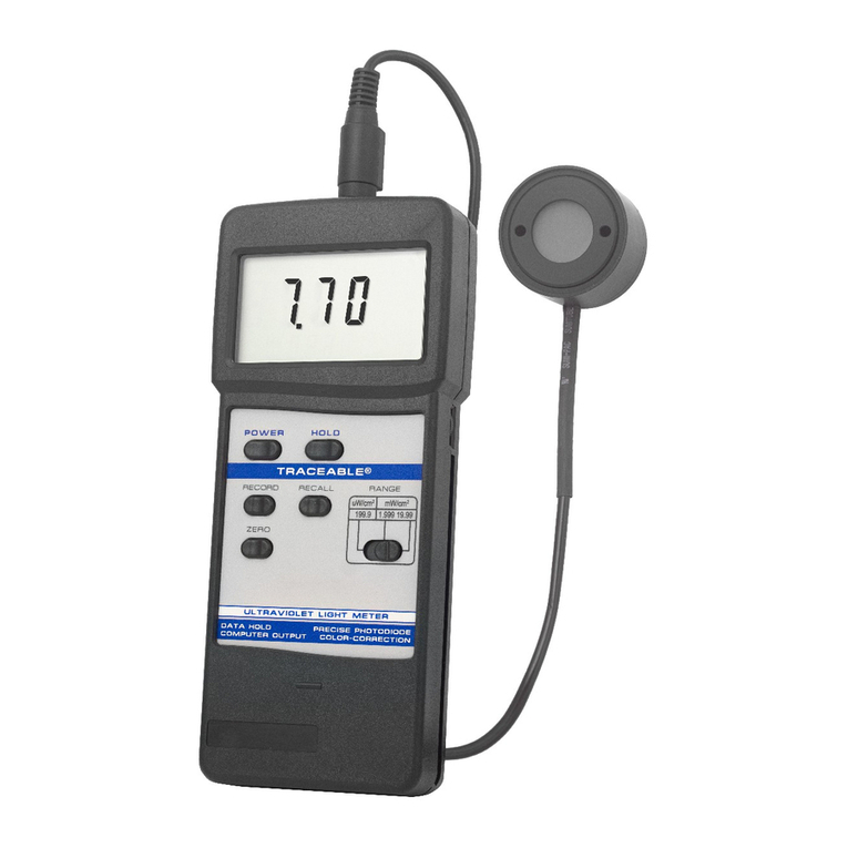
FIGURE 1:
DESCRIPTION
3-1 LCD
3-2 Power Button
3-3 Hold Button: press to hold reading
3-4 Record Button: press to record results
3-5 Recall Button: press to show minimum and maximum readings
3-6 Zero Button
3-7 Range Switch
3-8 UV Sensor
3-9 Sensor Plug
3-10 Sensor Input Socket
3-11 Computer Output Socket
3-12 Battery Compartment
UV LIGHT METER OPERATION
1. Turn the meter on by pressing the POWER BUTTON (3-2, fig. 1).
2. Zero Adjustment: Set the RANGE SWITCH (3-7, fig. 1) to 199.99. This is the far
left setting. Co er the UV SENSOR (3-8, fig. 1) with hand to protect it from the
en ironment for a more accurate zero reading. Press the ZERO BUTTON (3-6,
fig. 1). The display should read 0.0. Remo e your hand.
NOTE: if the display shows: “CALO” the further adjustment is needed. Turn the
power off by pressing the POWER BUTTON. Press and hold the ZERO
BUTTON. Press the POWER BUTTON again. The bottom line of the display will
show “0000”. Adjust the VR9 by turning the knob on the right of the unit until the
top line of the display reads “0”.
3. Select the desired range by switching the RANGE SWITCH (3-7, fig. 1) NOTE: If
the display shows “----” then there is too much light for the meter to read in this
range. Select the next higher range.
4. Place the UV SENSOR (3-8, fig. 1) directly under the light source you wish to
measure. Hold for at least 0.4 seconds. The meter will measure the light and
display the alue. Limit the angle of light from the source being measured to 45
degrees; if possible, limit the angle of light to within 30 degrees.
5. To hold a measurement on the display, press the HOLD BUTTON (3-3, fig. 1)
while a measurement is being taken. The LCD displays show DH in the upper
left portion of the display to indicate that the alue is a “held” alue. To cancel
the data hold feature, simply press the HOLD BUTTON a second time.
6. To record a measurement, press the RECORD BUTTON (3-4, fig. 1) while a
measurement is being taken. The LCD will show REC in the lower left portion of
the display to indicate that the alue is being recorded. To deacti ate the record
function, press the RECORD BUTTON again.
7. Memory Recall: Use the RECALL BUTTON (3-5, fig. 1) to recall the minimum
and maximum readings. When the REC symbol appears or the display, press
the RECALL BUTTON (3-6, fig. 1) once. The maximum recorded alue will be
displayed. The letters “Max” will also appear on indicating that this is the
maximum or highest reading. A second press of the RECALL BUTTON will
display the minimum reading. The letters “Min” will also appear indicating that
this is the minimum lowest reading.
Note: The Data Record function must be in use to utilize the Memory recall
features. Once the RECORD BUTTON has been pressed a second time to
deacti ate the data record function, the minimum and maximum alues are no
longer stored.
CARING FOR THE UV LIGHT METER
It is recommended that the meter be recalibrated e ery year. The sensor is extremely
sensiti e to humidity. Store in a low humidity en ironment by keeping it in its case with
the Humidity Sponge
™
pro ided. Proper storage will extend the length of time between
recalibration of the unit.
COMPUTER INTERFACE
This unit features Computer output. A COMPUTER OUTPUT SOCKET (3-11 fig. 1) is
located on the top of the unit. To utilize this feature, connect the unit to a PC with an
accessory Data Acquisition System. See Accessories.
BATTERY LIFE
If the letters “LBT” appear on the left corner of the display, it indicates the batteries are
low and need to be replaced. To replace the battery, slide the battery co er located on
the back of the unit away from the unit. Remo e the old battery and replace it with a
new 9-Volt alkaline battery. Use an alkaline battery, NOT a regular or hea y duty
battery. Property connect the battery. Replace the battery co er. Incorrectly installed
batteries may damage electronics.
The unit has an automatic shut off feature to prolong battery life. If no button on the
unit is pressed for ten minutes, the unit will automatically shut off. To deacti ate this
feature, press the RECORD BUTTON while a measurement is being taken.
ALL OPERATIONAL DIFFICULTIES
If this Ultra Violet Light Meter does not function properly for any reason, please replace
the battery with a new 9-Volt alkaline battery (see Low Batt section, abo e). Low
battery power can occasionally cause any number o “apparent” operational difficulties.
Replacing the battery with a new fresh battery will sol e most difficulties.


