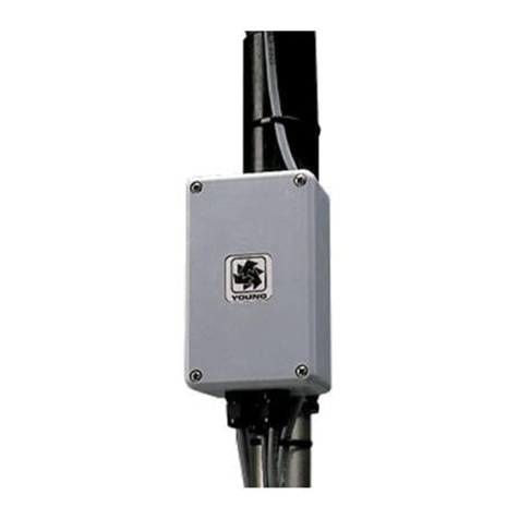
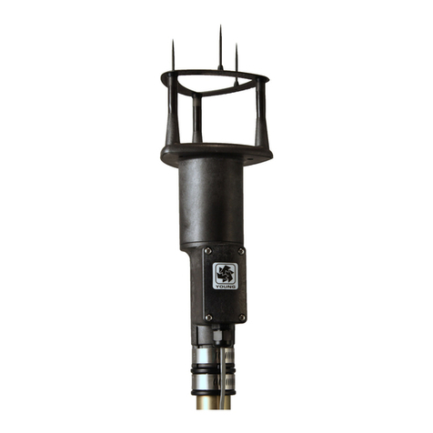
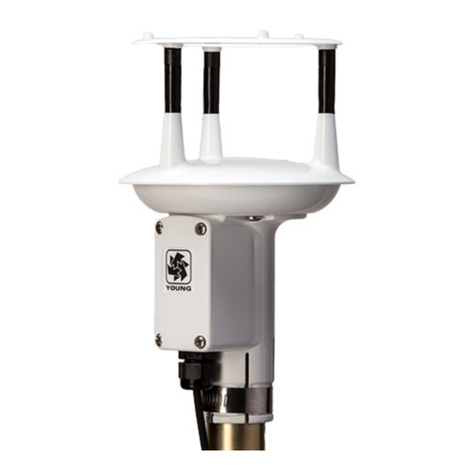
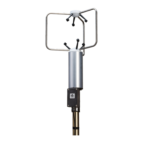
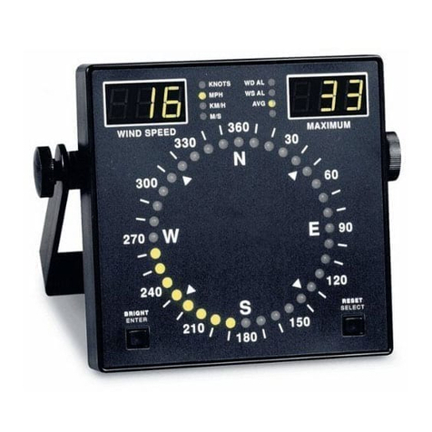
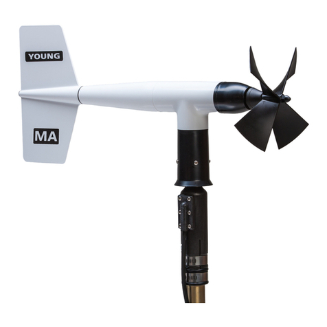
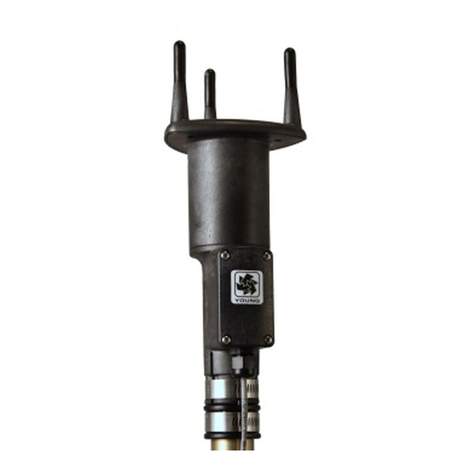
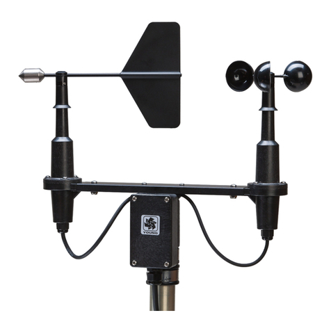
Young 81000 Reference manual

1 .
MODEL 81000
ULTRASONIC ANEMOMETER
OCTOBER 2001
MANUAL PN 81000-90
R. M. YOUNG COMPANY
2801 AERO-PARK DRIVE, TRAVERSE CITY, MICHIGAN 49686, U. S. A.
TEL: (231) 946-3980 FAX: (231) 946-4772

1.
MODEL 81000
ULTRASONIC ANEMOMETER
1.0 SPECIFICATION SUMMARY
WINDSPEED
Range: 0 to 40 m/s (0 to 90 mph)
Resolution: 0.01 m/s
Threshold: 0.01 m/s
Accuracy: ±1% rms ±0.05 m/s (0 to 30 m/s)
±3% rms (30 to 40 m/s)
WINDDIRECTION
Azimuth Range: 0.0 to 359.9 degrees
ElevationRange: ±60.0 degrees
Resolution: 0.1 degree
Accuracy: ±2° (1 to 30 m/s)
±5° (30 to 40 m/s)
SPEEDOFSOUND
Range: 300 to 360 m/s
Resolution: 0.01 m/s
Accuracy: ±0.1% rms ±0.05 m/s (0 to 30 m/s wind)
SONICTEMPERATURE
Range: -50 to +50 ºC
Resolution: 0.01 ºC
Accuracy: ± 2 ºC (0 to 30 m/s wind)
GENERAL
Air sample column: 10 cm high X 10 cm diameter
Air sample path: 15 cm
Internal sample rate: 160 Hz
Output sample rate: 4 to 32 Hz (selectable)
Output formats: Serial data (selectable)
4 voltage output channels 0 to 4000 mV
RS-232 full duplex
RS-485 half duplex (can be bussed)
Baud Rates: 1200 to 38400
Power Supply: 12 to 30 VDC, 4 watts
Dimensions: Overall height 56 cm
Support arm radius 17 cm
Mounting 34 mm (1.34 in) diameter
(standard 1 inch pipe)
Weight: Sensor weight 1.7 kg (3.8 lb)
2.0 INTRODUCTION
The Young Model 81000 measures three dimensional wind veloc-
ity based on the transit time of ultrasonic acoustic signals. From
speed of sound, sonic temperature is derived. Speed of sound and
sonic temperature are corrected for crosswind effects.
Measurement data are available as voltage output signals or serial
output using RS-232 or RS-485 connections. Both voltage and
serial output may be configured for various of output formats.
Operating parameters may be edited using ordinary terminal soft-
ware on a PC. Simple menus make it easy. All parameters are
stored in nonvolatile memory.
Superior environmental resistance is achieved by using UV stabi-
lized thermoplastic, stainless steel, and anodized aluminum com-
ponents. Electrical connections are made via an easily accessible
junction box. The unit mounts on standard 1 inch pipe, outside
diameter 34mm (1.34").
3.0 INITIAL CHECKOUT
Carefully unpack the unit and inspect for physical damage. Any
damage should be reported to the shipper. The 81000 arrives fully
calibrated and ready to use. A simple four-step operational check
may be performed as follows:
1. Remove junction box cover. Connect power and signal wires to
terminals as indicated in wiring diagram for "RS-232 output.
Connect serial cable to computer COM port.
2. Start an ordinary serial communications program (like Hyper-
Term) with baud rate at 38400 and flow control set to NONE.
3. Apply power to the 81000 sensor. There will be a brief delay for
initializationthentheunitwillbegintooutputdataatfourtimesper
second using the following format: speed (m/s) azimuth (deg)
elevation (deg) speed-of-sound (m/s) sonic-temperature (°C).
Verify that all values are present on the display. Typical output
is shown below:
0.00 0.0 0.0 346.70 25.14
0.00 0.0 0.0 346.68 25.11
0.00 0.0 0.0 346.76 25.25
0.00 0.0 0.0 346.80 25.30
0.00 0.0 0.0 346.76 25.25
0.00 0.0 0.0 346.80 25.30
0.00 0.0 0.0 346.80 25.30
0.00 0.0 0.0 346.82 25.35
A threshold level of 0.2 m/s is preset from the factory. Wind below
the threshold, such as in still air, is output as 0.00 m/s. Azimuth
may be any value from 0.0 to 359.9 degrees. When wind speed
is below threshold level, azimuth output is maintained at the last
value read before the wind went below threshold. Elevation
remains zero until threshold is exceeded. Speed of sound ranges
from 300 m/s to 360 m/s depending on temperature. At 20°C the
value is about 344 m/s. Sonic temperature may be compared to a
standard Celsius thermometer and should agree within ±2°C. If
values appear questionable or any value is not displayed, remove
power and check all wiring connections. If the problem cannot be
corrected contact your YOUNG representative.
4. Verify sensor response by gently blowing through the measuring
section. Wind from the north side (marked “N”), should produce a
positive SPEED response and an AZIMUTH display correspond-
ing to North (i.e.: values around 359.9 or 0.0 ). Wind from the
opposite direction should produce values indicating south,
(around 180.0) and so forth. Downward wind produces negative
ELEVATION values, upward wind produces positive values.

2.
After proper operation is confirmed, the sensor may be installed.
Complexdatacollectionorserialcommunicationschemesshouldbe
tested and verified before final installation. It is easier to confirm
wiring connections and communication protocol on a test bench
than a tower. Factory settings may be changed by following the
instructions in the next section.
4.0 COMMAND MENU
Sending the ESC character (ASCII 27) three times in quick succes-
siontakestheunitoutofOPERATEmodeandcausestheCOMMAND
MENUtoappear.
COMMANDS (VERSION 3.0.00)
-------------------------
R) REPORT
S) SETUP
X) EXIT TO OPERATE MODE
Access each menu item by sending the character associated with
the menu item of interest. Characters may be upper or lower case.
Send "X" to return to OPERATE mode. The following paragraphs
explain the function of each menu item and associated sub-menu.
The version number may differ from that shown above.
5.0 REPORT
REPORTsummarizescurrentparametersettings.Someparameters
are for factory diagnostics only and cannot be accessed or altered
by the user. Typical values appear below.
PATH LENGTH (cm) CH DELAY(uS) CL
------------------------------------
A 15.341 1 19.650 516
4 19.550 484
B 15.245 2 23.875 570
5 23.750 524
C 15.146 3 26.675 511
6 26.500 466
OUTPUT FORMAT: CUSTOM
34567 [ 3D-SPEED AZIMUTH ELEVATION SOS Ts ]
WIND SPEED UNITS: m/s
OUTPUT RATE: 4 Hz
SAMPLES FOR AVERAGE: 0
MODE: AUTO
WAKE CORRECTION: YES
ERROR HANDLING: OMIT INVALID DATA
VOLTAGE OUTPUT FORMAT: SPEED, AZIMUTH, ELEVATION, TEMP
VOLTAGE OUTPUT SCALE: 0 TO 40 m/s = 0-4000 mV
0 TO 540 DEG AZIMUTH = 0-4000 mV
-60 TO +60 DEG ELEVATION = 0-4000 mV
220 K to 320 K = 0-4000 mV
CORRELATION TOLERANCE: 125
COMPARE SHIFT: 0
MANUAL GAIN: 0
AGC LEVEL: 1125
AGC INCREMENT: 5
HI SPEED ADC SAMPLES: 10
THRESHOLD: 20 cm/s
TRANSDUCER FREQ REF: 8333
TRANSDUCER FREQ: 245.7 KHz
ACCESS LEVEL: NORMAL
6.0 SETUP
SETUP allows editing operating parameters to suit the needs of a
particular application. The SETUP menu and detailed explanation of
each menu item follows:
SET PARAMETERS
-------------------------
A) AVERAGING
B) BAUD
E) ERROR HANDLING
M) MODE
N) SCALING
O) OUTPUT RATE
P) POLL CHARACTER (ADDR)
S) SERIAL OUTPUT FORMAT
T) THRESHOLD
U) UNITS
V) VOLTAGE OUTPUT FORMAT
W) WAKE CORRECTION
X) EXIT TO MAIN MENU
6.1 AVERAGING
AVERAGING sets the number of output samples used to calculate
block averages of all measurements including voltage inputs. Aver-
aged results appear in both serial output and voltage output formats.
For no averaging, set NUMBER OF SAMPLES TO AVERAGE to
0. Otherwise, set it to the number of output samples to be used for
calculating the block average. The rate at which block averages
are output is determined by OUTPUT RATE and NUMBER OF
SAMPLES TO AVERAGE parameters. For example, if OUTPUT
RATEis4HzandNUMBEROFSAMPLESTOAVERAGEis8,theunit
will produce a block average output once every 2 seconds (0.5 Hz).
4 samples x 1 avg result = 1 avg result
second 8 samples 2 seconds
NUMBER OF SAMPLES TO AVERAGE: 0
ENTER NEW VALUE (0 - 320):
6.2 BAUDRATE
BAUD sets the baud rate for serial communication. Faster baud
rates may be required if the output string is long and the output rate
is fast (see OUTPUT RATE).
BAUD: 38400
----------------------
A) 1200
B) 2400
C) 4800
D) 9600
E) 19200
F) 38400
X) EXIT TO MAIN MENU
6.3 ERRORHANDLING
ERROR HANDLING determines the manner in which invalid mea-
surements are handled. Invalid measurements can occur when the
acoustic path of the sonic signal is blocked or internal circuits fail.
Acoustic blockage make be caused by rain drops, ice, snow, or
other debris. When set to INCLUDE INVALID DATA, an output
always occurs. If CUSTOM serial output is used, an ERROR CODE
may be included in the output to indicate the error condition. When
set to OMIT INVALID DATA, invalid measurements are not output.
See VOLTAGE OUTPUT for details regarding this setting when that
output is used.
ERROR HANLDING: 2
-----------------
1) INCLUDE INVALID DATA
2) OMIT INVALID DATA
X) EXIT
6.4 MODE
MODE sets the method by which internal samples are processed to
produce output samples. MODE may be set to MEAN, MEDIAN, or
AUTO. MEAN averages internal samples to produce an output
sample and is recommended for low wind velocities (<5 m/s).
MEDIAN finds the median of internal samples to produce an output
sample and is recommended for higher velocities (>5 m/s). AUTO
switches between MEAN and MEDIAN at 5 m/s to offer optimal
performance over an extended range.
DonotconfuseMODEwithAVERAGINGdescribedabove. Also,do
not confuse internal samples with output samples (See OUTPUT
RATE).
MODE 3
---------------------
1) MEAN
2) MEDIAN
3) AUTO
X) EXIT TO MAIN MENU

3.
6.5 SCALINGMULTIPLIER
SCALING MULT sets overall scaling for UVW, 2D, and 3D wind
speed outputs. Azimuth and elevation angle are not effected. The
default value of 10000 represents a scaling multipler of 1.0000.
Normally, this value should not be changed since each instrument is
calibrated in the YOUNG factory wind tunnel. However, users who
wish to alter the scaling based on independent calibration
assesment may use this parameter to do so.
SCALING MULT : 10000
ENTER NEW VALUE:
6.6 OUTPUTRATE
OUTPUT RATE sets the rate at which output samples are available.
Fast output rates and long serial output strings may require
higher baud rates in order to keep up with the outgoing data stream.
If AVERAGING is used, average results are available only after
enough output samples have been collected. See AVERAGING for
details.
OUTPUT RATE 4Hz
--------------------
A) 4 HZ
B) 5 HZ
C) 8 HZ
D) 10 HZ
E) 16 HZ
F) 20 HZ
G) 32 HZ
X) EXIT TO MAIN MENU
When using the RS-485 communication with higher output rates and
long output strings, the half-duplex scheme will spend more of its
time sending data with a progressively smaller window of time in
which to receive commands. In fact, if the string is long enough and
the output rate high enough, the 81000 will not be able to respond
to any commands. RS-485 is best used in POLLED MODE or at
modestoutputrates.Incontrast,the full-duplex nature of the RS-232
scheme is immune to the limitations described above. Commands
can be received while data is being sent.
6.7 POLLCHARACTER
POLL CHARACTER (ADDR) is used to set the address character
polledoperation(POLLCUSTOMoutputformat).AnyprintableASCII
character may be used to assign an address that uniquely identifies
the instrument. When bussed on an RS-485 network with other
81000 instruments, each one should have a different address
character.
POLL CHARACTER (ADDR) : A
ENTER NEW CHARACTER:
Topollthe81000,sendMA!whereAisthe POLLCHARACTER.The
81000 will respond with the POLL CHARACTER and a space
followed by the custom serial output string.
6.8 SERIALOUTPUT FORMAT
SERIAL OUTPUT FORMAT sets the output string for serial output.
Preset and custom formats are available.
SERIAL OUTPUT FORMAT 1
------------------------------------
1) CUSTOM
2) RMYT
3) NMEA
4) POLL CUSTOM
X) EXIT TO MAIN MENU
6.8.1 CUSTOM
CUSTOM format allows the user to construct an ASCII-printable
serial output string. Long strings may require higher BAUD rates or
lowerOUTPUT RATES.(See BAUDandOUTPUTRATE.)Also, see
UNITS.
When CUSTOM is selected the following message and sub-menu
appear:
CURRENT SERIAL OUTPUT FORMAT:
34567 [ 3D-SPEED AZIMUTH ELEVATION SOS Ts ]
CONSTRUCT AN OUTPUT FORMAT BY SELECTING FROM THE LIST BELOW.
ELEMENTS MAY BE IN ANY ORDER. REFER TO MANUAL FOR DETAILS.
----------------------------------------------------------
1) UVW
2) 2D SPEED
3) 3D SPEED
4) AZIMUTH
5) ELEVATION
6) SOS
7) Ts
8) ERR CODE
ENTER CUSTOM STRING (8 CHARACTERS MAX): 16
UVW is the orthogonal u, v, and w wind velocities. All three
values are output. Typically the 81000 is oriented with u-axis
aligned east-west and v-axis aligned north-south. In this
orientation, +u values = wind from the east; +v values = wind
from the north. Wind from below (updraft) = +w. Refer to
ORIENTATION KEY drawing for illustration.
2D SPEED is wind magnitude in the u-v plane.
3D SPEED is wind magnitude in three dimensional space.
AZIMUTH is the 0.0-359.9º wind direction angle in the u-v plane.
With the 81000 junction box facing south, 0.0° = north, 90.0° =
east, 180.0° = south, and 270.0° = west. Refer to ORIENTATION
KEY drawing for illustration.
ELEVATION is the ±90.0º wind elevation angle relative to the u-v
plane. Values are positive when wind is from below (updraft)
and negative when from above (downdraft). Effective elevation
angle measurements are limited to ±60.0°. Refer to ORIENTATION
KEY drawing for illustration.
SOS is the speed of sound.
Ts is the sonic temperature derived from SOS.
ERROR CODE indicates the validity of the measurement. Any
non-zero value idicates an invalid measurement. ERROR
HANDLING must be set to use this field.
6.8.2 RMYT
RMYT sends wind speed and direction in a format suitable for use
with the YOUNG Model 06201 Wind Tracker display unit. RS-485
outputs must be used. When RMYT is selected, the baud rate
is automatically set to 9600 and threshold set to 10 cm/sec.
6.8.3 NMEA
NMEA sends wind speed and direction in NMEA marine format to
Young Model 06206 Marine Wind Tracker display or other input
device. The sentence is $WIMWV,aaa,R,ss.s,N,A where aaa =
wind direction angle in degrees and ss.s = wind speed in knots.
When NMEA is selected, the baud rate is automatically
changed to 4800 and threshold set to 10 cm/sec.
4.
6.8.4 POLL CUSTOM
POLL CUSTOM format allows the 81000 to be polled for an output.
See CUSTOM for details on constructing the output string. Poll by
sending MA! where A is the POLL CHARACTER ADDRESS. Allow
at least 5 milliseconds between each poll command charac-
ter. The 81000 responds with the POLL CHARACTER followed by
the custom serial output string. Up to 32 sonic anemometers may be
networked using the RS-485 connection. By assigning a unique
address to each device, multiple units may run on the same network
and respond individually only when polled.
6.9THRESHOLD
THRESHOLD sets the wind speed threshold in cm/sec. With UVW
output format, the absolute value of wind magnitudes below thresh-
oldarereportedaszero.WithSPEEDAZIMUTHELEVATIONoutput
format, wind speeds below threshold are reported as zero, azimuth
output is maintained at the last value before the wind went below
threshold, and elevation remains zero until threshold is exceeded.
THRESHOLD (cm/s) :20
ENTER NEW THRESHOLD (cm/s, 0-500) :
6.10 UNITS
UNITS sets wind speed units for CUSTOM serial output. Resolution
associated temperature units are as follows:
cm/s 1 cm/s 0.01 K
m/s 0.01 m/s 0.01 °C
mph 0.1 mph 0.01 °F
km/h 0.1 km/h 0.01 °C
knots 0.1 kn 0.01 °F
UNITS 2
-------------------
1) cm/s
2) m/s
3) mph
4) km/h
5) knots
X) EXIT TO MAIN MENU
6.11 VOLTAGEOUTPUTFORMAT
VOLTAGE OUTPUT FORMAT selects one of two formats for scaled
voltage output on outputs V1, V2, V3, and V4. Format 1 selects U
V W, format 2 selects SPEED AZIMUTH ELEVATION. Output V4 is
SONICTEMPERATURE.Windspeedscalingmaybesetbytheuser.
Azimuth, elevation, and sonic temperture scaling is fixed. Regard-
less of format, full scale output is 0-4000 mV for each channel.
VOLTAGE OUTPUT FORMAT 2
------------------------
1) U V W TEMP
2) SPEED AZ ELEV TEMP
X) EXIT
After selecting the format, a prompt for scaling appears:
VOLTAGE OUTPUT SCALE: 0 TO 40 m/s
ENTER NEW VALUE (10-60) :
In UVW format, ± scaling is always implied. For example, entering a
value of 40 means a -40 to +40 m/s span. Note that for UVW format,
0 wind speed is 2000 mV or mid-scale. In the example above, -40 m/
s = 0 mV and +40 m/s = 4000 mV.
InSPEEDAZIMUTHELEVATIONformat,theSPEEDscalerepresents
positive wind speed only. The fixed scale for AZIMUTH is 0 to 540º
andELEVATION is -60° to+60°.An elevation value of0°= 2000 mV.
Foreitherformat,theSONICTEMPERATUREoutputscaleis220Kto
320 K = 0 to 4000 mV. When voltage outputs are used, the
SERIAL OUTPUT FORMAT must be set to CUSTOM even
though the serial output is not used.
See the accompanying wiring diagram for voltage output connec-
tion details. Note that when ERROR HANDLING is set to INCLUDE
INVALID DATA, voltage outputs go to full scale (4000 mV) when
invalid data is present.
6.12 WAKECORRECTIONS
WAKECORRECTIONenablesordisablesreal-timecorrectionalgo-
rithms. To compensate for flow distortions in the wake of support
struts and other mechanical features, each 81000 is individually
calibrated in the YOUNG factory wind tunnel (NIST traceble) to
generate a unique correction table which is stored in the unit.
Additional compensating algorithms correct for elevation angle
distortions and crosswind effects on speed of sound.
WAKE CORRECTION: YES
USE WAKE CORRECTION? (Y/N):
7.0 WARRANTY
This product is warranted to be free of defects in materials and
construction for a period of 12 months from date of initial pur-
chase. Liability is limited to repair or replacement of defective item.
A copy of the warranty policy may be obtained from R. M. Young
Company.
8.0 CE COMPLIANCE
This product has been tested and shown to comply with
European CE requirements for the EMC Directive. Note that
shielded cable must be used.
Declaration of Conformity
Standards to which Conformity is Declared:
EN55022Group 1 (CISPR22class B)
EN50082-1:1997using
EN61000-4-2:1995
EN61000-4-3:1995withENV50204:1995
EN61000-4-4:1995
EN61000-4-6:1995
Manufacturer’sName andAddress:
R.M. YoungCompany
TraverseCity, MI,49686,USA
Importer’sName and Address:
SeeShipper or Invoice
Type of Equipment:
MeteorologicalInstruments
Model Number / Year of Manufacture:
81000/2000
I,theundersigned, hereby declare that the equipment
specifiedconformsto the above Directives andStandards.
Date/ Place:
TraverseCity, Michigan,USAMay 1, 2000
DavidPoinsett
R&D Manager,R. M.Young Company


Table of contents
Other Young Measuring Instrument manuals

Young
Young 06201 User manual

Young
Young 05631C User manual

Young
Young 27106 User manual

Young
Young 86000-SDI User manual

Young
Young 09101 User manual

Young
Young 32400 SERIAL INTERFACE User manual

Young
Young 03002L User manual

Young
Young 81005A User manual

Young
Young Wind Sentry Series User manual

Young
Young ResponseONE 91000 User manual
Popular Measuring Instrument manuals by other brands

PCB Piezotronics
PCB Piezotronics 210B50 Installation and operating manual

Awair
Awair Lite AWAIR0HD3 quick start guide

Ametek
Ametek BARBEN ANALYTICAL OXY visor Installation, operation and maintenance manual

eXact
eXact Chlorine Plus instruction manual

Hach
Hach ORBISPHERE 3655 user manual

Viavi
Viavi SmartClass Fiber OLS-85 user guide