r--,.
( I
'.
'
'-~-~
o
G
Q
C~
(J
PREFACE
This
manual
provides
maintenance
information
for
the
display
terminal
hardware
only.
For
the
maintenance
of
any
applications
(hardware,
software,
or
firmware)
added
to
the
terminal,
refer
to
the
applicable
maintenance
manual
covering
that
application.
This
manual
is
also
the
only
training
document.
·Due
to
few
parts,
self-contained
diagnostics,
and
modular
construction
of
the
display
terminal,
no
classroom
instruction
is
offered.
By
carefully
reading
the
information
in
this
manual,
the
customer
engineer
(CE)
will
be
prepared
to
isolate
display
terminal
hardware
problems.
Section
1
lists
the
self-study
objectives,
and
section
6
lists
the
tasks
to
be
performed
before
responding
to
a
customer
request
for
maintenance.
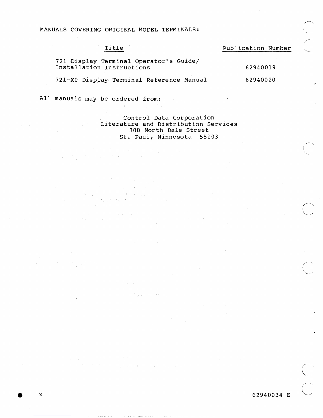
Reference
to
the
following
listed
manuals
may
be
necessary
during
maintenance.
These
manuals
are
divided
into
groups
which
cover
the
enhanced
model
terminals
and
the
original
model
terminals.
An
enhanced
model
terminal
is
either
a
new
production
CC634-B/CC638-B
unit
or
an
earlier
built
CC634-A/CC638-A
unit
with
the
YR109-A
enhanced
firmware
option
installed.
An
original
model
terminal
is
a
CC634-A/CC638-A
unit
without
the
YRI09-A
option
installed.
MANUALS
COVERING
ENHANCED
MODEL
TERMINALS:
Title
721
Enhanced
Display
Terminal
Operator's
Guide/Installation
Instructions
721
Display
Terminal
Owner's
Manual*
721
Enhanced
Display
Terminal
Hardware
Reference
Manual
Publication
Number
62950101
62940101
62940102
*The
owner's
manual
is
a
replacement
for
the
earlier
Operator's
Guide/Installation
manual
having
the
same
publication
number.
62940034
E
ix
,--,-''"_
..
,-,--,-''
'"
...
_.....
_,---,,,.,,',,.,,-----------_._,-----,,-".,,'---