Controlli GTX703-3G User manual

CONTROLLI S.p.A. - 16010 Sant’Olcese (GE) - Italy
Tel. +39 010 73061 | Fax +39 010 7306870/871
ISTRUZIONI DI MONTAGGIO / MOUNTING INSTRUCTIONS
Modulo Modem Wireless per GTX703
Wireless modem module for GTX703 GTX703-3G
1aEmissione / 1st Issue 06/19 1 DIM302
APPLICATION
The GTX703-3G is an optional module, available for GTX703,
that adds the ability to communicate with all machines and sy-
stems worldwide.
GTX703-3G provide:
• Wireless modem with a Micro-SIM slot
• 4 LED indicators (2 user programmable, Modem Status,
Network Status)
• 2 Digital Inputs
• 2 Digital Output
BSP v1.0.298 or greater is required
TECHNICAL CHARACTERISTICS
Cellular Technology
Frequency
Bands
GSM 4-band: 850/900/1800/1900MHz
UMTS 5-band: 800/850/900/1900/2100MHz
Transmission
Data
HSDPA category 8: Max 7.2Mbps
HSUPA category 6: Max 5.76Mbps
UMTS: Max 384kbps (DL)/Max 384kbps (UL)
EDGE: Max 296kbps (DL)/Max 236.8kbps (UL)
GPRS: Max 107kbps (DL)/Max 85.6kbps (UL)
CSD: 14.4kbps
1. ANTENNA
2. LED 1-4
3. INPUTS 1-2/OUTPUTS 1-2
4. SIM SLOT
5. PLUG-IN EXTENDER
APPLICAZIONE
GTX703-3G è un modulo opzionale, disponibile per GTX703,
che aggiunge la capacità di comunicare con tutte le macchine e
i sistemi in tutto il mondo.
GTX703-3G fornisce:
• Modem wireless con uno slot Micro-SIM
• 4 indicatori LED (2 programmabili dall’utente, Stato mo-
dem, Stato rete)
• 2 Ingressi Digitali
• 2 Uscita Digitale
È richiesto BSP v1.0.298 o versione successiva
CARATTERISTICHE TECNICHE
Tecnologia cellulare
Bande di
frequenza
GSM 4-band: 850/900/1800/1900MHz
UMTS 5-band: 800/850/900/1900/2100MHz
Trasmissione
dati
HSDPA category 8: Max 7.2Mbps
HSUPA category 6: Max 5.76Mbps
UMTS: Max 384kbps (DL)/Max 384kbps (UL)
EDGE: Max 296kbps (DL)/Max 236.8kbps (UL)
GPRS: Max 107kbps (DL)/Max 85.6kbps (UL)
CSD: 14.4kbps

Transmitting
Power
Class 4 (33dBm±2dB) for GSM850 and EGSM900
Class 1 (30dBm±2dB) for DCS1800 and PCS1900
Class E2 (27dBm±3dB) for GSM850 and EGSM900
8-PSK
Class E2 (26dBm±3dB) for DCS1800 and PCS1900
8-PSK
Class 3 (24dBm+1.7/-3.7dB) for UMTS
800/850/900/1900/21
Interface
Antenna GSM/UMTS antenna, 50Ω, SMA-F Female con-
nector
Digital inputs 2x 24 Vdc with optical isolation
Digital ou-
tputs 2x SSR with optical isolation
LED indica-
tors 4
SIM slot microSIM
Plug-in
extender yes
Environment Conditions
Operating
Temp -20°C to +60°C
Storage
Temp -20°C to +70°C
Operating
/ Storage
Humidity
5 - 85% RH , non condensing
Protection
Class IP20
Dimensions and Weights
WxHxL 41.20x23.80x90.30 mm
Weight 0.2 Kg
Approvals
CE
EN 61000-6-4, EN 61000-6-2, EN 61000-6-3, EN
61000-6-1
EN 60945
ETSI EN 301 489-1, ETSI EN 301 489-52
EN 301 511
ETSI EN 301 908-1, ETSI EN 301 908-2
EN 62311
EN 60950-1
UL cULus: UL61010-1 / UL61010-2-201
UL cULus: Class I Div. 2
DNV-GL Yes
RCM Yes
WIRELESS MODEM
Behavior of the wireless modem can be congured from the
HMI device System Setting tool:
System Settings → Network → Mobile Network
The Mobile Network section is available only when the optional
module is plugged to the HMI device.
PARAMETER DESCRIPTION
Enabled Enable the Wireless Modem
Autostart Enable the Wireless Modem automatically
when HMI device is power on
Potenza
trasmittente
Classe 4 (33dBm±2dB) per GSM850 e EGSM900
Classe 1 (30dBm±2dB) per DCS1800 e PCS1900
Classe E2 (27dBm±3dB) per GSM850 e EGSM900
8-PSK
Classe E2 (26dBm±3dB) per DCS1800 e PCS1900
8-PSK
Classe 3 (24dBm+1.7/-3.7dB) per UMTS
800/850/900/1900/21
Interfaccia
Antenna GSM/UMTS antenna, 50Ω, SMA-F connettore
femmina
Ingressi
digitali 2x 24 Vdc con isolamento ottico
Uscite digitali 2x SSR con isolamento ottico
LED 4
SIM slot microSIM
Estensione
Plug-in si
Condizioni ambientali
Temp. funzio-
namento -20°C a +60°C
Temp. imma-
gazinamento -20°C a +70°C
Umidità
operativa / di
stoccaggio
5 - 85% RH , senza condensa
Classe di
protezione IP20
Dimensioni e peso
WxHxL 41.20x23.80x90.30 mm
Peso 0.2 Kg
Certicazioni
CE
EN 61000-6-4, EN 61000-6-2, EN 61000-6-3, EN
61000-6-1
EN 60945
ETSI EN 301 489-1, ETSI EN 301 489-52
EN 301 511
ETSI EN 301 908-1, ETSI EN 301 908-2
EN 62311
EN 60950-1
UL cULus: UL61010-1 / UL61010-2-201
UL cULus: Class I Div. 2
DNV-GL Yes
RCM Yes
MODEM WIRELESS
Il modem wireless può essere congurato dallo strumento Sy-
stem Setting del pannello operatore:
System Settings → Network → Mobile Network
La sezione Mobile Network è disponibile solo quando il modulo
opzionale è collegato al pannello operatore.
PARAMETRO DESCRIZIONE
Enabled Abilita il Modem Wireless
Autostart Abilita automaticamente il Modem Wireless
quando il pannello operatore è acceso
SIM PIN Codice PIN della SIM card se richiesto
1aEmissione / 1st Issue 06/19 2 DIM302

SIM PIN SIM Card PIN code if required
APN
APN (Access Port Name)
If you do not know this information please con-
tact your mobile services provider.
Roaming Enable Roaming option if required
Authentication
Select the authentication mode. Could be:
• None
• PAP (Password Authentication Protocol)
Username
Password
Username and password to be used when the
authentication mode is selected
SIM CARD INSTALLATION
GTX703-3G uses Micro-SIM SIM Card format.
Insert SIM card with chip side facing GTX703-3G module front
side, as shown in the below image.
Once inserted the Micro-SIM in the apposite slot push it until
you hear a “click” sound, this means that the Micro-SIM has
been fully and correctly installed into the Micro-SIM slot.
APN
APN (Access Port Name)
Se non conosci queste informazioni, contatta il
tuo gestore di telefonia mobile.
Roaming Abilita l’opzione Roaming se necessario
Authentication
Seleziona la modalità di autenticazione.
Potrebbe essere:
• Nessuna
• PAP (Protocollo Autenticazione Password)
Username
Password
Nome utente e password da utilizzare quando è
selezionata la modalità di autenticazione
INSTALLAZIONE DELLA SIM CARD
GTX703-3G utilizza il formato scheda SIM Micro-SIM.
Inserire la scheda SIM con il lato frontale rivolto verso il lato del
modulo GTX703-3G, come mostrato nell’immagine sottostante.
Una volta inserita la Micro-SIM nell’apposita fessura, spingerla
no a sentire un “click”, questo signica che Micro-SIM è stata
installata completamente e correttamente nello slot Micro-SIM.
1aEmissione / 1st Issue 06/19 3 DIM302

WSystem Setting tool:
System Settings → Plugins → PLCM09
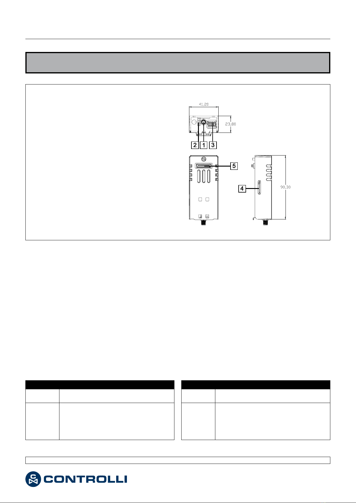
Digital I/O Description
Input-1
Input-2
User congurable:
• None
• Cloud: 0=down, 1=up
When the input signal is on, HMI device will connect
to remote cloud. When it is off, the remote cloud will
be disconnected.
• Mobile: 0=down, 1=up
When the input signal is on, HMI device will start the
wireless modem. When it is off, the wireless modem
will be disconnected.
• 1=system reboot
When the input signal is detect to be 1, HMI device
will force a reboot
Output-1
Output-2
User congurable:
• None (not used)
• User controlled
Output signal will be managed by the HMI applica-
tion
• Cloud: down=0, up=1
Output will be set to 1 when cloud connection is
active, 0 when not active
• Mobile: down=0, up=1
Output will be set to 1 when wireless modem con-
nection is active, 0 when not active
Led Description
LED #1
LED #2
User congurable:
• None (not used)
• User controlled
LED status will be managed by the HMI application
• Cloud: down=off, up=on, error=blink
Show the cloud connection status
• Mobile: down=off, up=on, error=blink
Show the mobile connection status
LED #3
Show the wireless modem status:
OFF = Disabled
ON = Enabled
LED #4 Show the network activity (blinking)
LED E I/O DIGITALI
Il comportamento dei primi due LED disponibili e degli I/O digi-
tali può essere congurato dallo strumento System Setting del
pannello operatore:
System Settings → Plugins → PLCM09
I/O Digitali Descrizione
Input-1
Input-2
Congurabile dall’utente:
• None
• Cloud: 0=down, 1=up
Quando il segnale di ingresso è attivo, il pannello
operatore si collegherà al cloud remoto. Quando è
spento, il cloud remoto verrà disconnesso.
• Mobile: 0=down, 1=up
Quando il segnale di ingresso è attivo, il pannello
operatore avvierà il modem wireless. Quando è
spento, il modem wireless verrà disconnesso.
• 1=riavvio del sistema
Quando il segnale in ingresso viene rilevato come 1,
il dispositivo HMI forzerà il riavvio
Output-1
Output-2
Congurabile dall’utente:
• None (non usato)
• Controllato dall’utente
Il segnale di uscita sarà gestito dall’applicazione HMI
• Cloud: down=0, up=1
L’uscita sarà impostata su 1 quando la connessione
cloud è attiva, 0 quando non è attiva
• Mobile: down=0, up=1
L’uscita sarà impostata su 1 quando la connessione
modem wireless è attiva, 0 quando non è attiva
Led Descrizione
LED #1
LED #2
Congurabile dall’utente:
• None (non usato)
• Controllato dall’utente
Lo stato dei LED sarà gestito dall’applicazione HMI
• Cloud: down=off, up=on, errore=lampeggiante
Mostra lo stato della connessione cloud
• Mobile: down=off, up=on, error=lampeggiante
Mostra lo stato della connessione mobile
LED #3
Mostra lo stato del modem wireless:
OFF = Disabilitato
ON = Abilitato
LED #4 Mostra l’attività di rete (lampeggiante)
1aEmissione / 1st Issue 06/19 4 DIM302

Le caratteristiche contenute in questa pubblicazione possono essere modifi cate senza preavviso
The performances stated in this sheet can be modifi ed without any prior notice
Il dispositivo contiene componenti elettrici ed elettronici e non può essere smaltito con i riuti domestici. Vanno rispettate le normative locali
sullo smaltimento.
The device contains electrical and electronic components and is not allowed to be disposed of as household refuse. All locally valid regula-
tions and requirements must be observed.
1aEmissione / 1st Issue 06/19 5 DIM302
INSTALLATION
It is possible to apply the plug-in as follows:
INSTALLAZIONE
E’ possibile applicare il modulo come segue: