Conveying & Hoisting Solutions Star User manual

Form 3000 Issued 15th May 2013
Page 1 of 7
Star Swivel-Arm Hoist
Installation and Operating Instructions
Conveying & Hoisting Solutions P/L
ABN 78 163 744
1. Purpose of Equipment
Star Swivel-Arm Hoists are intended for the transport of materials. Star Hoists are not intended for the carriage of humans or
animals.
2. Safety
2.1 Warnings
Read and understand these instructions first before setting up or operating this equipment
Keep these instructions accessible near the Hoist.
Before beginning work, one should become familiar with the working environment.
No changes, additions or modifications may be made to the Hoist or associated equipment.
Do not modify, remove, bypass or override the safety devices.
Do not use this Hoist if there is any damage or unusual performance. Isolate the Hoist as described in Chapter 6.1 Emergency
Shutdown.
Do not operate the Hoist if there is a risk of people being endangered by the load or load carrying devices. Have the area
around the Hoist barricaded off and post warning notices.
Observe National Plant Regulations and Occupational Health and Safety Regulations.
Do not set-up, operate or allow loads into the NO GO Zone for power lines.
2.2 Hazard Assessment
Hazard Checklist: Please note that this checklist is indicative only. Users must perform their own Risk Assessment subject to
the intended siting and use of the equipment.
Hazard
Risk
Control
Crushing or Striking by the
Hoist tipping or collapsing
Moderate
Ensure the lifting wire rope is in good order and wrapped neatly on the winch
drum. Poorly wrapped rope can lead to rope failure causing the load to fall,
resulting in death or injury.
Ensure the supporting structure is adequate.
Check the Hoist has been correctly installed and that all locking pins and keepers
are in place.
Check the Upper Travel Limit Switch operates correctly (refer Fig. 4).
Do not overload the Hoist.
Keep personnel clear of the Hoist when in use.
Use control methods to avoid the load or hook catching or snagging during use,
leading to possible component failure or structural collapse.
Do not use the wire rope as a sling –attach to the hook only.
Crushing or striking by
material falling from the
Hoist.
Moderate
Have the area under the Hoist barricaded and prevent personnel entering the area.
Do not overfill attachments.
Ensure attachments are of adequate design, strength and correctly applied.
Check attachments are correctly attached to the hook.
Do not use where wind speeds are greater than 70km/hr.
Entanglement during use or
maintenance
Low
Ensure body parts, clothing or other materials are kept clear of the winch drum.
Cutting, stabbing or
puncturing from the lifting
wire rope
Low
Use gloves when checking wire rope condition.
Slipping, tripping or falling
Low
Place barricading at the edge of the structure and wear height safety equipment to
prevent a fall.
Adopt safe working practices when installing, maintaining or using the Hoist.
Place power leads so they do not become a tripping hazard.
Electrocution
Moderate
Use an E.L.C.B., an R.C.D. or other “safety switch” in the power supply.

Form 3000 Issued 15th May 2013
Page 2 of 7
Do not allow the Hoist or load to enter the NO GO Zone for Power Lines.
Prevent moisture from coming into contact with leads and plugs.
Do not alter or tamper with electrical parts.
Explosion
Low
Before use, ensure there are no explosive substances present near the Hoist.
2.3 Certification
Certification to operate this equipment is not required. The person with control or management of the workplace must ensure that:
the Operator is at least 18 years old
the Operator is competent to operate the equipment
a Dogman or Rigger is used to load the hoist if slinging practices are required.
2.4 Incident Notification
The employer, as defined by the Regulations referred to below, who has management or control of the workplace must be aware
that they may have an obligation to notify WorkCover of any incidents involving this equipment. Refer to the Occupational
Health and Safety Act and the Occupational Health & Safety (Incident Notification) Regulation(s) applicable to your State.
2.5 Inspections
Before the start of each work period, the person operating the Hoist should:
Ensure the work area is clean and well arranged.
Check the electric cable and plug for damage.
Check the wire rope for damage and wear. Run the hook down to the ground and then, using gloves, pull out the wire rope
while pressing the DOWN button. Once all the rope has been withdrawn, inspect the rope looking for kinks, bends, twists
flattened areas or other defects. Do not use the Hoist if the wire rope is damaged. Rewind the wire rope onto the winch drum,
keeping tension on the wire rope so that it wraps tightly and neatly. Ensure kinks or bends are not put into the wire rope
during this process. Untidy loosely wrapped wire rope can lead to damage or failure of the wire rope.
Check the hook and safety latch. Ensure the latch closes properly below the hook tip.
Inspect the mounting of the Hoist and ensure all fittings are tight and/or secured. Ensure the locking pin on the mounting
Yoke is in place and locked.
Inspect the load carrying devices and ensure they are undamaged.
Check the operation of the Upper Travel Limit Switch.
Ensure barricading and signage is present and legible.
3. Specifications
Item
Units
Specification
Power
V, Hz
240, 50
Drive Rating
kW
1.0 at 2800rpm
Operating Time (Duty Cycle)
ED%
60
Wire Rope size, construction, minimum breaking strain
mm, -, kN
5, 18x7 non rotating, 12.1
Lifting speed
m/min
32
Mass basic unit, scaffold clamp, floor to ceiling prop, tripod frame, window frame
kg
52, 16, 60, 95, 31
Outreach from pivot point
mm
800 to 1050
Minimum Headroom
mm
410
Noise emission
DB (A)
80.0
4. Description
4.1 General View
Fig.1: Star winch / motor unit with mounting Yoke
Index
1: Winch head
2: Motor & gearbox
3: Mounting tube
4: Upper Travel Limit
5: Wire rope
6: Load hook assembly
7: Power lead & plug
8: Hand Control socket
9: Yoke
10: Slew release
11: Mounting tabs
12: Folding Cotter Pin.
13. Securing Pin with
Cotter Pin
10
1
2
3
4
5
7
8
9
11
12
13

Form 3000 Issued 15th May 2013
Page 3 of 7
4.2 Controls
4.3 Upper Travel Limit Switch
4.4 Slew Locking Lever
To slew or swivel the Hoist:
With one hand, grip the locking lever (1)
and move the lever up until the lever is at
(2). The locking bar (5) will disengage from
the mounting system.
With the other hand, grip a part of the Yoke
(3) and slew or swivel the Hoist and yoke
around the pivot point (4), until the desired
point is reached.
Lock the Hoist in the new position by
moving the locking lever (1) back to it’s
6
Fig. 3: Hand Control
Fig. 2: Hand Control with Emergency Stop
3
4
4
3
2
1
1
5
5
Index
1: Hanging hook
2: EMERGENCY STOP
3: UP button
4: DOWN button
5: Connecting lead
Index
1: Hanging hook
3: UP button
4: DOWN button
5: Connecting lead
Fig 4: Upper Travel Limit Switch
Up motion may be stopped by the hook assembly striking the bar and operating the limit switch.
1
2
3
Index
1: Striker bar
2: Actuating cam
3: Limit switch
Fig. 5: Slew (swivel) Control
1
2
3
4
Index
1: Locking lever at
locked position
2: Locking lever at
unlocked position
3: Yoke strut
4: Pivot point
5: Locking bar
5
3
11

Form 3000 Issued 15th May 2013
Page 4 of 7
original position, where the locking bar (5)
will engage with the mounting system.
5. Operation
5.1 Pre-operation
Read, understand the warning notices given in Chapter 2.1 above before operating the Hoist.
Undertake and implement a Job Safety Assessment as outlined in Chapter 2.2 above before operating the Hoist.
Always secure the Hoist against unauthorised use. Do not leave the hand control lying around at the end of work periods.
Never leave the Hoist loaded. Unload before leaving unattended.
Always watch the suspended load from the operating point.
Do not stand or work under a suspended load.
Do not operate in wind speeds more than 70km/hr
Wear personal safety equipment
Do not stand on load carrying devices
Do not transport people
5.2 Switching On and Off
Refer to Chapter 4.2: Controls
Hold the control with the Hanging Hook (1) uppermost.
1. Unlock the emergency stop switch (2), where fitted, by turning the knob in the direction of the arrows.
2. Move upwards: press the UP button (3).
3. Move downwards: press the DOWN button (4).
4. Switch Off or Stop: Release the UP (3) or DOWN (4) button or press the EMERGENCY-OFF button (2).
5.3 Lifting a Load
1. Slew the Hoist so that it is able to lift over a clear space. Refer to Chapter 4.4 Slew Locking Lever.
2. Press and hold the DOWN button until the hook reaches the pick-up point. Refer to Chapter 5.2 Switching On and Off.
Caution: do not allow the hook to land and the wire rope to become loose on the drum. See Chapter 2.2 Risk
Assessment for the hazards involved and chapter 2.5 Inspections for corrective action.
3. Attach the load as required. Refer to Chapter 2.3 Certification.
4. Press and hold the UP button to raise the load to the required height. Refer to Chapter 5.2 Switching On and Off.
5. Slew the Hoist so that the load may be set down at the new level. Refer to Chapter 4.4 Slew Locking Lever.
6. Land the load at this new level by pressing the DOWN button until the load lands. Release the DOWN button immediately
and do not allow the wire rope to become slack.
5.4 Lower a Load
Lowering a load is the reverse of the instructions given in Chapter 5.3 Lifting a Load
6. Operator Maintenance
6.1 Daily Maintenance
The Operator should carry out the instructions given in Chapter 2.5 Inspections
6.2 Weekly Maintenance
In addition to the instructions given in Chapter 2.5 Instructions, the Operator should oil the pivot point of the mounting Yoke.
7. Shut-down Procedure
7.1 Emergency Shut-down
Stop operation of the Hoist by either:
1. releasing the UP or DOWN buttons (see Figures 2 & 3)
2. pressing the EMERGENCY-OFF button, if fitted (see Figure 2)
3. pulling out the hand control from the socket on the winch/motor unit (see Figure 1)
4. turning off the power supply.
Remove the hand control and power supply from the hoist.
Secure the load hook and/or load against uncontrolled movement (wind etc).
Erect a sign stating “DO NOT USE – HOIST UNDER REPAIR” and fix to the hoist.
Inform management or management’s agent of the situation.

Form 3000 Issued 15th May 2013
Page 5 of 7
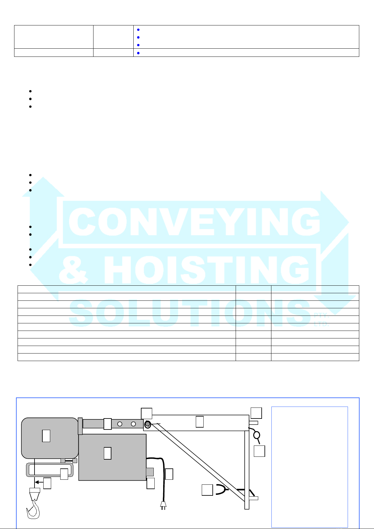
7.2 End of Work Period/Hire Shut-down
Unload the Hoist and raise the hook up to the Upper Travel Limit Switch.
Remove the hand control and the power supply.
Secure the winch/motor against unwanted movement by engaging the Slew Locking Lever on the mounting Yoke.
Clean any dirt or grease from the Hoist.
8. Installation
8.1 Preparation
When installing the Hoist, ensure that:
Read and understand all instructions before installation, particularly Chapter 2 (Safety) and Chapter 5 (Operation).
Ensure that placement of the equipment conforms to the “No Go Zones for plant near overhead powerlines” rules.
The mounting position is firm, stable and capable of withstanding the forces of the Hoist, its load and its operation.
An inspection has been carried out on the equipment before installation, as described in Chapter 2.5 above.
Unauthorised personnel are prevented from entering the mounting area during installation.
Personal safety equipment is worn.
The winch/motor unit is exactly horizontal, to ensure correct wire rope wrapping.
When using the window clamp, ensure the brickwork is of sufficient strength to support the loading imposed and that the
brickwork extends above and over the window opening.
With hollow block brickwork, use load distributing bearers between clamp arms and wall.
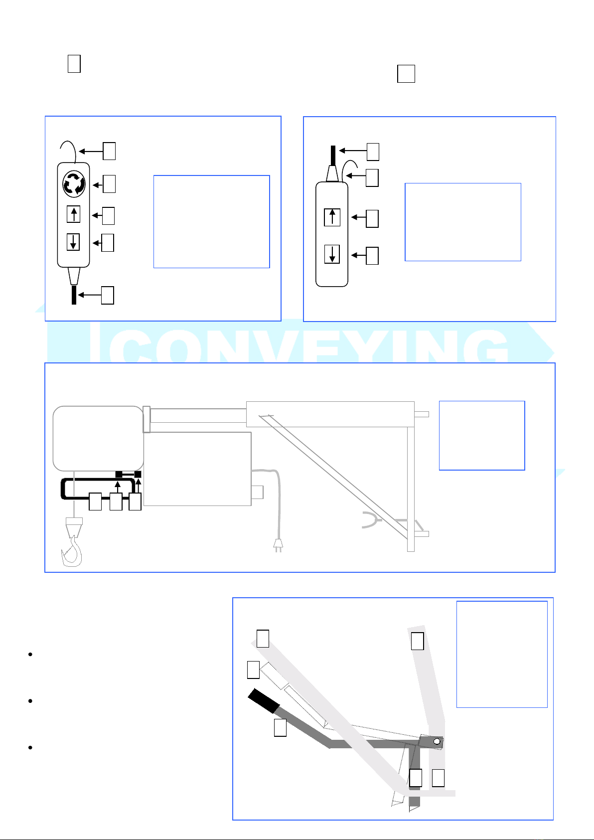
8.2 Scaffold Bracket
1. The scaffold clamp (21) is fastened to the scaffolding
with the scaffold coupling.
2. To prevent falls, fit handrail tubes each screwed to two
vertical frames with 90 degree couplings (32).
3. In addition to the normal scaffold anchorage, anchor
the vertical frame (22), to which the swivel arm hoist
is fastened, at the top and bottom to the building (23)
(anchor tensile and compressive strength, minimum
1.5kN) and brace sufficiently (25).
4. Hang swivel arm and secure with folding cotter pin.
8.3 Counterweight Frame
1. Assemble the tripod away from an edge due to
the danger of a fall during assembly.
2. Lay out both U section rails (16) on level ground
in a triangle.
3. Fit on the ballast box (17) or counterweight frame.
Fit standpipe (18) and struts (19). The standpipe
can be turned 180º on axis according to the
direction the swivel arm is to be swung in.
4. Tighten down strut (19) fixing bolts at both ends.
Tighten standpipe (18) fixing bolt and adjust
Stabiliser (21) so that it rests against the floor.
5. Hang swivel arm hoist and secure with folding
cotter pin.
6. Slide complete tripod with swivel arm hoist and
ballast box or counterweight frame (17) carefully
18
19
21

Form 3000 Issued 15th May 2013
Page 6 of 7
to the work edge.
7. Mount all 18 counterweights, or load the ballast
box with 400kg of solid material.
8. The hoist is always to be operated from behind
the side protection.
8.4 Window Clamp
Application: Wall widths 240 to 500mm
with window minimum opening width 950mm
and minimum opening height 1200mm
1. Open out window clamp (26), insert pin
through strut (27) and secure.
2. Position vertical tube (28) in window
opening at either left or right side as shown.
3. Fit clamp tube through socket, ensuring fixed
clamp plate (29) is located against the
outside wall, and secure with pin.
4. Fit clamp plates with spindles to opposite
ends of clamp tubes and lock into position
with pins. Tighten against outside wall.
5. Attention: with hollow block brickwork,
use load distributing bearers between clamp
plates and wall
6. Hang swivel arm and secure with folding
cotter pin.
8.5 Floor to Ceiling Prop
Load can be swung in with window opening widths
from 700mm onwards
Telescopic from 2300 to 3250mm.
Attention: when used on balconies etc, the balcony
must not be overloaded by the hoist.
1. Install the floor to ceiling tie (33) by screwing out the
lower spindle (35) between the ceiling and floor with
the large end plate (34) at the top and set up in such a
way that the boom is stopped in the swung out position.
2. Hang the swivel arm hoist and secure with folding
cotter pin.
8.6 Hanging the Swivel Arm
Refer to Fig. 1 Star winch / motor unit with mounting Yoke.
1. Fit the mounting Yoke to the fixing attachment by pacing the Tabs (11) over the appropriate spigots.
2. Secure the Yoke at the top Tab with the attached folding Cotter Pin (12).
3. Slew the Yoke so that it is over the landing, as described in Chapter 4.4 Slew Locking Lever.
4. Slide the winch/motor unit mounting Tube (3) inside the larger diameter tube on the mounting Yoke.
5. Secure with the Securing Pin and Cotter Pin (13).
6. Attach the Hand Control plug to the Hand Control socket (8).
7. Attach the power lead and plug (7) to an appropriate outlet. If extension leads are required, do not allow more than 30m of 3-
core 2.5mm2of lead to be attached.
16

Form 3000 Issued 15th May 2013
Page 7 of 7
9. Removal
Have the work area cordoned off and warning signs erected.
Disassembly of the hoist is carried out in reverse order to the installation.
Table of contents
Popular Winch manuals by other brands

Harken
Harken 42.2 Parts and Installation Service

MSA
MSA SURE STRONG SCE1074021050 Instruction for operation and maintenance

Globestock
Globestock G.Winch Service manual

Warn Industries
Warn Industries 9-A-30 Series quick start guide

Smittybilt
Smittybilt XRC 3.0 installation instructions

Savwinch
Savwinch CS Series Installation, operation & maintenance manual

Mile Marker
Mile Marker HI9000 Installation and operator's manual

Comeup
Comeup CP-200 Assembly

GEBUWIN
GEBUWIN WW250 D/Ex Series operating instructions

Mile Marker
Mile Marker SEC8 Scout ES Installation & operator's manual

Harken
Harken 70.3 ST EL Installation and maintenance manual

Grizzly
Grizzly H7604 instruction manual