T-MAX ATW 6000 User manual

M730904A
FITTING INSTRUCTIONS
CONTENTS
12V 7305100 Non-Radio Control (Wire Rope)
12V 7305101 Radio Control ( Wire Rope)
12V 7305110 Non-Radio Control (Synthetic Rope)
12V 7305111 Radio Control (Synthetic Rope)

T-MAX
UTV SERIES
DANGER
!
CAUTION
!
WARNING
!
01
INTRODUCTION
Thanks for your interesting in T-MAX Products, especially the ATW6000, and
we sincerely hope that it will satisfy you. We not only have the professional
capability to design winches but also with comprehensive after-sale
service. Please do not hesitate to contact us for any further messages or
suggestions.
Please do tell us the following information when you need to replace any parts of
winch:
1. The series no. of winch, for instance 88808290001 which is shown no the top of
the winch base.
2. The item no. of winch spare parts which is listed on the table of winch spare parts.
3. The exactly description of winch spare parts.
GENERAL SAFETY PRECAUTIONS
Please read and understand this owner’s manual before installing and using your
new winch. Pay particular attention to the General Information. Your winch is a very
powerful machine. If used unsafely or improperly, there is a possibility that property
damage or personal injury could result. We have included several features in this
winch to minimize this possibility. However, your safety ultimately depends on your
caution when using this product.
As the operator of this product the responsibility for safe operation ultimately lies
with you. It is imperative that you read and understand all of the safety precaution
instructions prior to installing and operation your winch. Failure to understand the
proper operation of this product can result in serious injury and/or property damage.
Indicates a hazardous situation which, if not avoided, will result in
death or serious injury.
Indicates a potentially hazardous situation which, if not avoided,
will result in death or serious injury.
Indicates a potentially hazardous situation which, if not avoided,
may result in minor or moderate injury. The notation is also used to alert you to
unsafe practices.

T-MAX
UTV SERIES
Note:
1. The above symbols in the Owner’s manual are used to indicate additional
information in the installation and operation procedures.
2. ATW6000 is designed primarily for intermittent duty general use. This
winch is not designed to be used in industrial or hoisting applications.
ATW6000 does not warrant it to be suitable for such use. T-MAX
manufactures a separate line of winches for industrial/commercial use.
Please contact us for further information.
UNPACKING
This carton contains the following items. Please unpack carefully.
Packaging list of ATW6000
Description Qty Remark
ATW6000, W/ WIRE ROPE or W/SYNTHETIC ROPE 1
HAND CONTROL 1 Without Radio; Two
kinds of hand control
are optional.
ROCKER SWITCH 1
CONTROL BOX 1
RADIO HAND CONTROL 1 Radio Version.
RADIO CONTROL BOX 1
ROLLER FAIRLEAD or ALUMINUM FAIRLEAD 1
MOUNTING HARDWARE KIT 1
OWNER’S MANUAL 1
MOUNTING PLATE 1
LONG CABLE 2
SHORT CABLE 3
02

T-MAX
UTV SERIES
6000LBS WINCH PARTS LIST
03

T-MAX
UTV SERIES
EXPLODED VIEW OF ATW6000
Item
Description Qty
1 GB/T70 M6×120 Bolt M6 X 120 2
2 7305100.1.1-1 Motor End Cover 1
3 7241100.1.1.3.1 Carbon Assy 1
4 7241100.1.1 Stator 1
5 7241100.1.2 Rotor 1
6 GB/T-85 M6×18 Bolt M6X18 4
7 7305100.0-1 Control Box Mount Bracket 1
8 7305100.1-1 Motor Base 1
9 7305100.0-4 Coupling Joint 1
10 GB/T276-1994 Bearing 2
11 7305100.2 Drum Assy 1
12 7305100.0-2 Tie Rod 2
13 7241100.3-9 Sun Gear 1
14 7241100.0-3 Spring 1
15 7241100.8-7 Washer 1
16 7241100.3-3 Inner Gear- Output 1
17 7241100.5 Braking System 1
18 7241100.3.1-4 Gear Spindle 3
19 7241100.3.1-1 Gear Carrier 2
20 GB/T276-1994 61812 Bearing 2
21 7241100.3.1-3 Planetary Gear 3
22 7241100.3-4 Anti-friction Gasket 1
23 7241100.3-5 Inner Gear 1
24 7305100.3-1 Motor Base 1
25 7241100.3-8 Clutch Yoke 1
26 7241100.3-7 Inner Lock washer 1
27 7241100.3-2 Gear Box Tube 1
28 GB/T3452.1 23.6×1.80 O Ring 1
29 7305100.3-3 Clutch Cover 1
30 7305100.3-2 Clutch Handle Assy 1
31 7241100.0-2 Mounting Plate 1
32 GB/T5782-2000 M8×20 Bolt M8 X20 2
33 7241100.4 Roller Fairlead(match to Wire Rope) 1
34 7241100.7 Wire Rope 1
35 9163151 Synthetic Rope 1
36 7309200.7-2 Aluminum Fairlead(match to Synthetic
Rope) 1
37 RU104206 Clevis Hook 1
38 7241100.6-1 Short Black Cable (25mm2 x 5cm)
(wrapped by Black Thermoplastics
Pipes) 1
04
Part No.

T-MAX
UTV SERIES
05
EXPLODED VIEW OF ATW6000’s CONTROL BOX
No. Description Qty
1 7329200.6A-10 Plug Cover 1
2 7329200.6A-11 Socket 1
3 7241100.6.5-1 Mini box 1
4 7241100.6.5-2 Radio Sender &
Receiver 1
5 7241100.6.1 ISM 1
6 GB/T93 6 Washer 8
7 GB/T41 M6 Nut 8
8 7241100.6.5-3 Mounting Plate 1
9 GB/T70.2
M5×10 Bolt 8
10 7241100.6.5-4 Control Box soleplate 1
39 7241100.6-2 Short Black Cable (25mm2 x 10cm)
(wrapped by Red Thermoplastics
Pipes) 1
40 7241100.6-3 Short Black Cable (25mm2 x 10cm)
(wrapped by Yellow Thermoplastics
Pipes) 1
41 7241100.6.2 (W) Control for ATV Use (match to Wire
Rope) 1
7241100.6.2 (S) Control forATV Use (match to Synthetic
Rope) 1
42 7241100.6-4 Long Cable (25mm2 x 180cm) 2
43 7241100.6.3 (W) Remote Handle Control for UTV &
Utility Use (match to Wire Rope) 1
7241100.6.3 (S) Remote Handle Control for UTV &
Utility Use (match to Synthetic Rope) 1
44 7241100.6.4 (W) Control Box Assy(match to Wire Rope) 1
7241100.6.4 (S) Control Box Assy(match to Synthetic
Rope) 1
45 7241100.6.5 Radio Hand Control 1
Part No.

T-MAX
UTV SERIES
DEMENSION
Note: The unit of dimension is mm.
Features & Specications:
P/N: 7305101(Radio Control)
P/N: 7305100(Non-Radio Control)
Rated Line Pull: 6000 lbs (2720kgs) Single-line
Motor: 12V , 1.3HP (Series Wound)
Control: Radio Control / Remote Control
Gear Ratio: 148:1
Clutch: Turn 90°By Hand wheel
Barking: Eccentric Block Type
Drum Size: Diameter 2.08” (53mm) x Length 5.33” (128mm)
Recommended Battery:650CCA Minimum for Winching
Fairlead: Roller Fairlead
Wire Rope: Length x Diameter (18mX6.8mm)
Mounting Bolt Pattern: 6.02” (153mm) x 4.33”(110mm)
Weight: 17KGS(37.5Lbs)
Overall Dimensions: (LxWxH) 15.08”x5.12”x7.32”(383mm x 130mm
x186mm)
P/N: 7305111(Radio Control)
P/N: 7305110(Non-Radio Control)
Rated Line Pull: 6000 lbs (2720kgs) Single-line
Motor: 12V , 1.3HP (Series Wound)
Control: Radio Control / Remote Control
Gear Ratio: 148:1
Clutch: Turn 90°By Hand wheel 06

T-MAX
UTV SERIES
Barking: Eccentric Block Type
Drum Size: Diameter 2.08” (53mm) x Length 5.33” (128mm)
Recommended Battery:650CCA Minimum for Winching
Fairlead: Aluminum Fairlead
Synthetic: Length x Diameter (15m x7.5 mm)
Mounting Bolt Pattern: 6.02"(153mm) x 4.33"(110mm)
Weight: 15KGS(33Lbs)
Overall Dimensions: (LxWxH) 15.08"x5.12"x7.32"(383mm x 130mm
x186mm)
Line Pull Line Speed Motor Current
lbs (kgs) ft/min (m/min) Amps
0 39.4 (12) 40
1000 (454) 21.3 (6.5) 100
1500 (680) 14.8 (4.5) 120
2000 (907) 11.2 (3.4) 140
2500 (1134) 8.9 (2.7) 160
3000 (1360) 7.5 (2.3) 170
3500 (1587) 6.2 (1.8) 190
4000 (1814) 5.6 (1.7) 200
4500 (2040) 5 (1.6) 220
5000(2270) 4.9(1.5) 230
5500(2500) 4.6(1.4) 260
6000(2720) 4.3(1.3) 280
Above performance specs are based on rst layer of drum
Wire rope layer Pulling power Cable Capacity per Layer
1st is closest to drum lbs (kgs) ft(m)
1st 6000 (2720) 11(3.4)
2nd 4850 (2200) 25(7.6)
3rd 4070(1850) 41(12.5)
4th 500 (1260) 59(18)
INTERMITTENT DUTY
ATW6000 is like any other motor driver power tools such as an electric drill
or saw. The electric motor should not be allowed to become excessively hot.
Normally precautions will extend the life of your motor. Keep the duration of
pulls as short as possible. If the end of the motor becomes uncomfortable
hot to touch, stop winching and allow the motor to cool down.
07

T-MAX
UTV SERIES
If the winch motor stalls, do not continue to apply power to
the winch.
GERNERAL SAFTEY PRECAUTIONS
ATW6000 is a powerful machine. Treat it with respect, use it with caution and
always follow the safety guidelines.
The wire rope or synthetic rope before the winch stalls. For
heavy loads, use a pulley block to reduce the load on the wire rope.
1. Maximum working load capacity is on the rst layer closest to the drum
is around 6000lbs (2040kgs). Do not overload. Do not attempt prolonged
pulls at heavy loads. Overloads can damage the winch and/or the wire
rope and create unsafe operating conditions. For loads over 1,000 pounds
we recommend the use of a pulley block to double line the wire rope.
This reduces the load on the winch and the strain on the wire rope by
approximately 50%. Attach hook to load bearing parts. The vehicle engine
should be running during winch operation. If considerable winching is
performed with the engine of, the battery may become too weak to re-start
the engine.
2. After reading and understanding this manual, learn to use your winch.
After installing the winch practice using it.
3. Do not move your vehicle to assist the winch in pulling the load. The
combination of the winch and vehicle pulling together could overload the wire
rope and winch.
4. Keep a safety distance. Ensure that all people stand well clear of winch
during the operation. Always stand clear of wire rope, hook and winch. To
avoid the unlikely event of component failure, it is best that you and other are
out of harms way.
5. Inspect the wire rope and equipment frequently. A frayed wire rope with
broken strands should be replaced immediately. Always replace wire rope
with T-MAX’s identical replacement part. Periodically check the winch
installation to ensure that all bolts are tight.
6. Use leather gloves when handling the wire rope. Do not let the wire rope
slide through your hands even when wearing gloves.
7. Never winch with less than 5 turns of wire rope or synthetic rope around
WARNING
!
CAUTION
!
08
T-MAX
UTV SERIES
the winch drum since the wire rope end fastener will not withstand a load.
8. Always use the hand saver bar or hook strap (if so equipped) when
guiding the wire rope in or out.
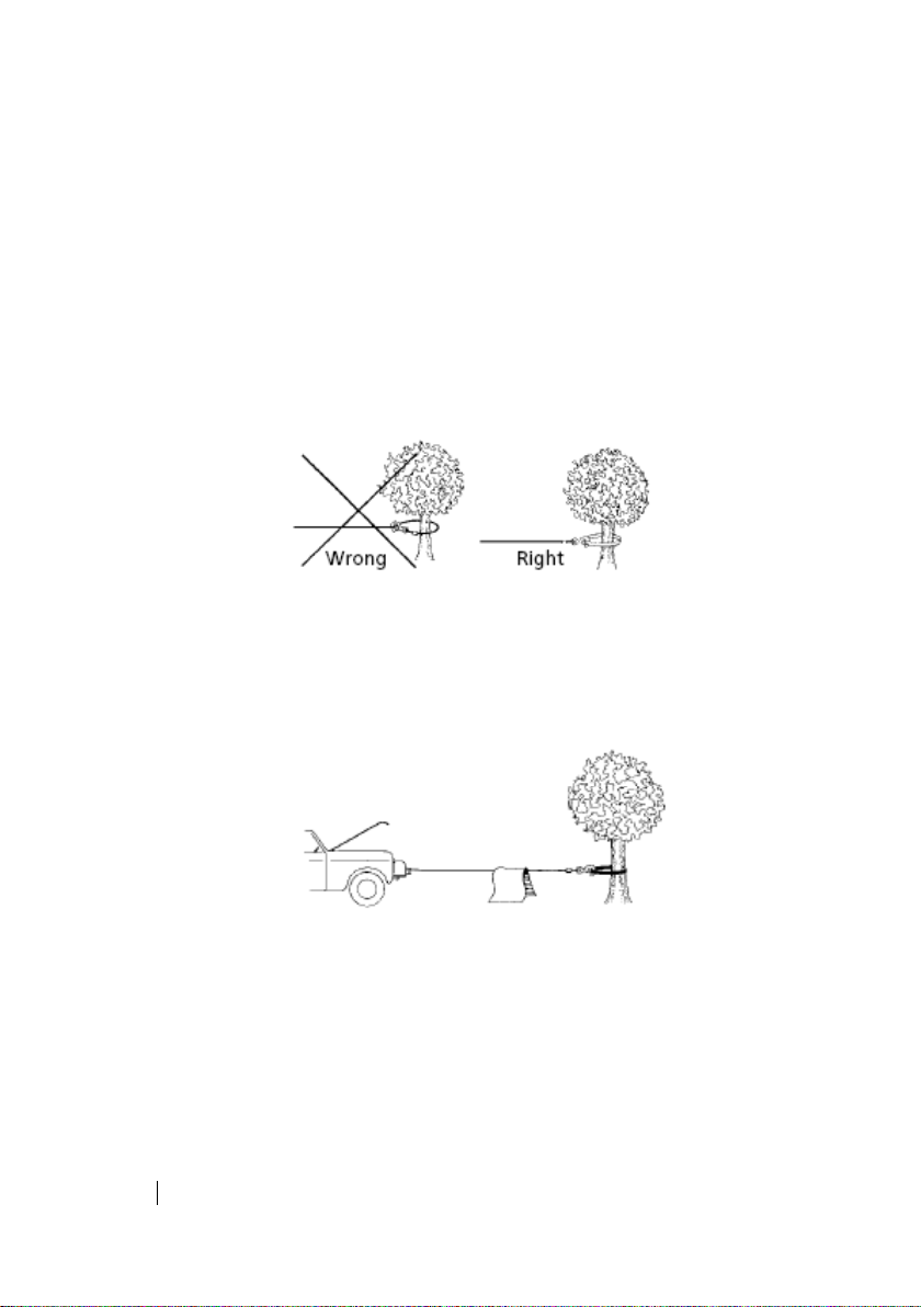
9. Keep clear of the winch, taut wire rope and hook when operating the
winch. Never put your nger through the hook. If you nger should become
trapped in the hook, you could lose your finger. Never hook the wire rope
back onto itself because you could damage the wire rope. Use a nylon sling.
(See Figure 5)
Figure 5
10. If a wire rope failure should occur, the cloth will act as a damper and help
prevent the rope from whipping. (See Figure 6)
Figure 6
11. Your winch is not designed or intended for overhead hoisting operations.
Never use your winch for lifting or moving people.
12. Avoid continuous pulls from extreme angles as this will cause the wire
rope to pile up at one end of the drum. This can jamb the wire rope in the
winch, causing damage to the winch or the wire rope.
13. Always operate the winch with an unobstructed view of the winching
09

T-MAX
UTV SERIES
operation. Equipment such as tackle, hooks, pulley blocks, straps, etc.
should be sized to the winching task and should be periodically inspected for
damage that could reduce their strength.
14. Take appropriate precautions to disable the winch when not in use or
under supervision to prevent use by children or other unauthorized persons.
Do not operate the winch when under the influence of drugs, alcohol or
medication.
15. When moving a load, slowly take up the wire rope slack until it becomes
taut. Stop, recheck all winching connections. Be sure the hook is properly
seated. If a nylon sling is used, check the attachment to the load.
16. When using a winch to move a load, place the vehicle transmission in
neutral, set the vehicle parking brake and chock the wheels.
17. Do not machine or weld any part of the winch. Such alterations may
weaken the structural integrity of the winch.
18. Do not power the winch longer than 120 seconds. The drum and wire
rope/synthetic rope may get too hot
19. Do not connect the winch to either 110C AC house current or 220V mains
as winch burnout or fatal shock may occur. Never allow shock loads to be
applied to the winch or wire rope.
20. Use caution when pulling or lowering a load up and down a ramp or
incline. Keep people, pets and property clear of the path of the load.
INSTALLATION
MOUNTING YOUR WINCH
Please reading and understanding the following prescription:
Step (1)
Choose a mounting location that is sufficiently proper and safe to install
your winch. Pay attention to the different brand and model of the vehicle, the
mounting location may be also different. The safety mounting location must
be plane and the thickness must be at least 0.31inch (8mm).
Do dill four holes which diameter is 10.5mm and position is 152mmX110mm.
(see Figure 7)
10

T-MAX
UTV SERIES
Figure 7
Step (2)
Open up the package,take out the winch and winch spare parts,then
mount the winch as following figure. Let the mounting bolt through
the holes(which is drilled in Step(1)) and the mounting plate from the
bottom up.
Note: To use the mounting bolts (M10x35mm)and washer 0.4inch(10mm)
which are supplied by T-MAX.
Step (3)
Turn the clutch handle to the direction of “out”;
Let the wire rope through the roller fairlead;
To connect the clevis hook on the wire rope;
Turn the clutch handle as 90°reversely to the direction of “in” to
engaged the clutch;
Note: To turn the drum slightly,the cluch is engaged if it could not be
turned;or to repeat as”a” once more;
To x the roller fairlead on the mounting plate.
Note: If the rope is synthetic rope, you can x the aluminum fairlead on
the mounting plate, and then reel the rope. Please see the method of
how to do that as the attached interleaf.
11

T-MAX
UTV SERIES
Installation Drawings
Control Box
Step(4) Mounting Control Box
Discharge two bolt which is at the side of the control box,and then to
screw the two bolt through the hole of the mounting palte and x the
control box tightly with a wrench for Allen screws.
12
(C)
(+)
(B)
(D)

T-MAX
UTV SERIES
b. According to the above Figure of the Electric Theory, to connect the
point “B”, “C” and “D”.
Step(5) Mounting the Control
Note: This Step is aim to who purchase the ATW6000 with control,
If you Purchase the ATW6000 with Remote Handle control ,overleap
this step.
To install the Control (which is for ATV use) on the left handlebar;
To fasten the Control (which is for ATV use) after to readjust it on a
suitable position;
Note:
1. The current is circulated when the vehicle works.
2. Do wrap the cable with rubberized fabric to make sure all the wires is
orderly.
Step (6) Electrical Connection
Pay close attention to proper electrical cable connection as follows
Long Red Cable (length: 1.8m; square millimeter 25mm2), one terminal
to the bottom terminal of the motor, and the other terminal connecting
to positive (+) terminal of the battery the red terminal of the motor.
Long Black Cable (length: 1.8m; square millimeter 25mm2), one
terminal to the bottom terminal (A) of the motor, and the other terminal
connecting to negative (-) terminal of the battery the red terminal of the
motor.
Note:
1. Be sure battery cables are not drawn taught across any surfaces,
which could possible damage them.
2. Be sure battery cables are not drawn taught across any surfaces,
where is too hot or tight.
3. Clean all connections especially in remote control switch and
receptacle.
13

T-MAX
UTV SERIES
Figure of the Electric
Theory
[1] [2] is optional
14

T-MAX
UTV SERIES
Battery Cable Wiring Diagram
Step (7) Check the Winch
Before to operate your winch, please check the following issues:
1. All connections of cables is correct;
2. No cable or tie-in is uncovered well;
3. All cables should be wrapped by Thermoplastics Pipes;
4. To disengage the clutch, turn on the remote control as “OUT”
position. Cable may be free spooled off the drum;
5. To engage the clutch, turn on the remote control as “IN” position.
The winch is now ready for pulling.
MAINTENANCE
Periodically check tightness of mounting bolts and electrical
connections. Clear any dirt or corrosion that may have accumulated on
the electrical connections.
15

T-MAX
UTV SERIES
NOTE:
Repair should be done by Authorize T-MAX Repair Centers ONLY.
Do not attempt to disassemble the gear box. Disassembly will avoid
warranty.
The safety precautions and instructions discussed in this manual can’t
cover all possible conditions and situations that may occur. It must
be understood by the operator that common sense and caution are
factors, which cannot be built into this product, but must be applied by
the operator.
16

This manual suits for next models
4
Table of contents
Popular Winch manuals by other brands


Harken
Harken Powered Performa Winch 50.2 STP EL Installation and maintenance manual

Orvea
Orvea Italwinch RT-02 manual

Westfalia
Westfalia 80 29 47 instruction manual

Clarke
Clarke Strong-Arm CHP 250 Operating & maintenance instructions

Champion Power Equipment
Champion Power Equipment EWD8000 Assembly & operating instructions

Pullmaster
Pullmaster M50 Instructions and parts manual

RAM
RAM 1550-8 AK1G Instructions, parts and maintenance manual

Comeup
Comeup HV-8000SP instruction manual

haacon
haacon 4216.0,25 operating instructions

Superwinch
Superwinch Tiger Shark 18000 manual

Mile Marker
Mile Marker PE5000 Installation & operator's manual

XI MAN
XI MAN 9500LB Owner's manual & safety instructions