manuals.online logo
Brands
  1. Home
  2. •
  3. Brands
  4. •
  5. Warn
  6. •
  7. Winch
  8. •
  9. Warn M15000 User manual

Warn M15000 User manual

INSTALLATION INSTRUCTIONS
WARN
ELECTRIC WINCH
M15000
CAUTION
CAUTION
NOTICE TO INSTALLER:
THE WINCH USER MUST RECEIVE THIS PAMPHLET FOR
DETAILED SERVICE INFORMATION
DO NOT INSTALL THIS WINCH BEFORE YOU HAVE READ AND
UNDERSTAND THE OPERATOR'S MANUAL. IT CONTAINS
IMPORTANT SAFETY INFORMATION
WARN
INDUSTRIES
12900 SE Capps Road
Clackamas, Or. 97015-8903 USA
1.800.543.9276
FABRICATION
INSTRUCTIONS
If you choose to fabricate your own mounting plate, follow the
dimensions and tolerances closely. Damage resulting from Improper mounting is
specifically excluded from warranty. Use grade 5 or better fasteners.
3.75
7.50
24.00
8.50
8.40
MIN
4.50
5.75
2.14
C
L
5.00
10.00
C
L
10.00 5.00
1.25
1.88
.62
.44 DIA.
(4 HOLES)
+.02
.00
.50 x 1.00
(2 SLOTS)
ALTERNATE REINFORCING METHODS
ANTI-THEFT PROTECTION
WELD
WELD
MOUNTING
BRACKET
CUT A SHORT LENGTHOF CHANNEL AND
WELD OVER THE WINCH MOUNTING CAPSCREWS
DO NOT WELD CAPSCREWS
TOLERANCES NOT
SHOWN ±.02
USE 5/16” THICK STEEL
PLATE, MINIMUM
P/N 61949 REV C0
INSTALLATION INSTRUCTIONS
The mounting hole pattern is of critical importance to the strength of your winch. For
winches that are not mounted on a factory mounting plate, it is recommended that
you use a winch mounting bracket as that shown on the last page, applying the
illustrated hole pattern, hole diameters and tolerances.
WINCH MOUNTING
CAUTION
CAUTION
1. The winch is to be mounted with feet forward on a vertical mounting plate. In
this situation the 8" x 1-1/4" fairlead slot must be centered between the lower
holes in the vertical mounting plate. To install: First align the upper holes in
the drum supports with the upper holes in the mounting plate and secure
loosely with two 7/16-14 x 1-1/2 grade 5 hex head capscrews and
lockwashers. The lockwashers must be under the head of all capscrews.
Next Insert two 7/16-14 x 1-1/2 grade 5 hex head capscrews with
lockwashers through the fairlead and lower holes in the vertical mounting
plate and secure loosely in the corresponding holes of the drum supports.
Tighten the above capscrews to 30 lb. ft. (4.14 Kg-m) torque. NOTE: DO
NOT FASTEN FAIRLEAD DIRECTLY TO THE DRUM SUPPORTS.
2. NOTE: Be sure that the drum rotates freely with the clutch disengaged. If the
drum binds or does not rotate freely, the mounting plate is not flat. Place shim
washers between the winch and mounting plate until the drum rotates freely.
3. Place flat washer shims as necessary between the bottom (horizontal) flange of
the mounting plate and the drum support. Insert two 7/16-14 x 1-3/4 hex head
capscrews with lockwashers and flat washers through the mounting plate and
into the threaded holes in the drum supports. Tighten to 30 lb. ft. torque.
CAUTION
BE SURE YOUR WI
NCH IS MOUNTED ON A MOUNTING
SYSTEM RATED FOR SAFE OPERATION AT 15000
LBS. NOT ALL WARN MOUNTING KITS MAY BE
SUITABLE FOR YOUR WINCH. CONTACT WARN
CUSTOMER SERVICE FOR FACTORY MOUNTING KIT
RECOMMENDATIONS.
TO AVOID DAMAGE T
O THE DRUM SUPPORT BRACKETS
DO NOT USE FASTENERS LONGER THAN THOSE
RECOMMENDED. DO NOT FASTEN FAIRLEAD TO DRUM
SUPPORTS.
DO NOT WELD THE HEAD OF ANY BOLT OR CAPSCREW
used for attaching the winch mounting kit or bumper kit.
Metallurgical changes, after welding, can occur and cause
the fasteners to become brittle and break, even under no-
load conditions. This could result in personal injury or
property damage.
SOLENOID PACK INSTALLATION
1. The solenoid pack should be mounted to the winch drum support (as shown below) using
the bolt provided in hardware pack. NOTE! THE SOLENOID PACK MUST BE
GROUNDED TO CHASSIS GROUND IN ORDER TO OPERATE.
2. The small black vinyl boots provided should be slipped over loose ends of control pack
cables (labelled as F1, F2, and A) prior to installation of the control pack. Once nuts on
motor terminals have been installed and tightened, slide boot over the nut and terminal to
cover the terminal.
ELECTRICAL CONNECTIONS
After mounting winch on bumper or custom mounting.
NOTE: BEFORE CONNECTING THE 72” CABLE, BE SURE TO CLEAN
BATTERY TERMINALS.
1. Connect the 72 inch red cable to the positive terminal of the battery.
2. Connect the 72 inch black cable to the ground screw on the motor and the
negative terminal of the battery.
3. Before initial use of your winch, plug in the remote control and test for proper
forward and reverse operation, keeping hands free of wire rope.
WARNING
NOTE: A fully charged "Heavy Duty" battery in the 90 amp/hour rating range
(650 or larger cold cranking amps) is required to obtain full performance from your
winch.
CLUTCH OPERATION
THE CLUTCH IS LOCATED ON THE GEAR HOUSING. Engage clutch to power in
load by rotating the clutch lever counter clockwise
CLUTCH ENGAGED
FREE SPOOL
TO FREE SPOOL, rotate the clutch lever a full 180°
CAUTION
WARNING
KEEP HANDS AWAY FROM WIRE ROPE AND
HOOK WHILE TESTING.
THE CLUTCH LEVER MUST BE IN FULL ENGAGED POSITION,
OR DAMAGE TO WINCH MAY OCCUR. It may be necessary to
jog the motor or drum in order to align the gear for engagement.
DO NOT ROTATE THE CLUTCH OUT OF
THE
"ENGAGED" POSITION WHILE UNDER LOAD.
THE BRAKE WILL NOT FUNCTION WITH THE
SPOOL IN "FREE SPOOL"

Other Warn Winch manuals

Warn 72008 User manual

Warn

Warn 72008 User manual

Warn 12-A-1D Series User manual

Warn

Warn 12-A-1D Series User manual

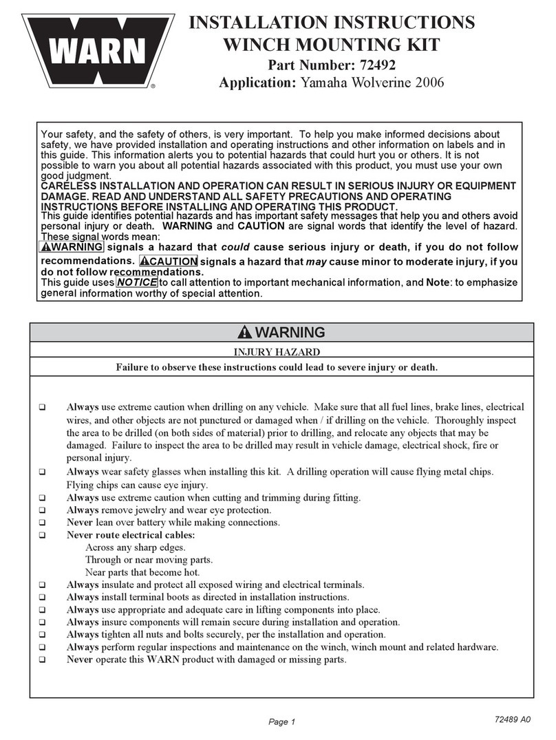
Warn 72492 User manual

Warn

Warn 72492 User manual

Warn 2.5ci User manual

Warn

Warn 2.5ci User manual

Warn VR EVO User manual

Warn

Warn VR EVO User manual

Warn 71983 User manual

Warn

Warn 71983 User manual

Warn 102600 User manual

Warn

Warn 102600 User manual

Warn Endurance 12.0 User manual

Warn

Warn Endurance 12.0 User manual

Warn 90250 Troubleshooting guide

Warn

Warn 90250 Troubleshooting guide

Warn TABOR 8000 User manual

Warn

Warn TABOR 8000 User manual

Warn Tabor 10000 User manual

Warn

Warn Tabor 10000 User manual

Warn 60272 User manual

Warn

Warn 60272 User manual

Warn 84704 User manual

Warn

Warn 84704 User manual

Warn VRX User manual

Warn

Warn VRX User manual

Warn XT25 User manual

Warn

Warn XT25 User manual

Warn VR EVO User manual

Warn

Warn VR EVO User manual

Warn 61019 User manual

Warn

Warn 61019 User manual

Warn Zeon Control Pack Relocation Kit User manual

Warn

Warn Zeon Control Pack Relocation Kit User manual

Warn PullzAll Specifications

Warn

Warn PullzAll Specifications

Warn A2000 User manual

Warn

Warn A2000 User manual

Warn 99963 User manual

Warn

Warn 99963 User manual

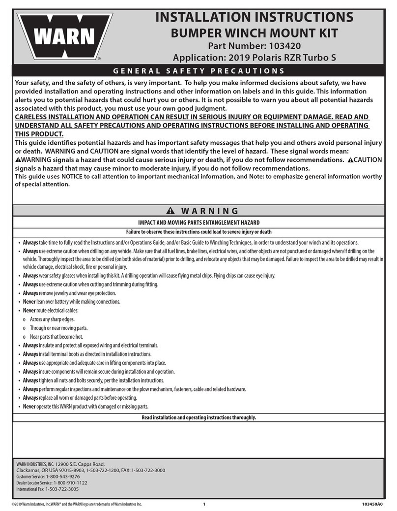
Warn 103420 User manual

Warn

Warn 103420 User manual

Warn 9.0Rc User manual

Warn

Warn 9.0Rc User manual

Warn 70924 User manual

Warn

Warn 70924 User manual

Popular Winch manuals by other brands

Portable Winch PCW3000 user guide

Portable Winch

Portable Winch PCW3000 user guide

Allied W400 Series Service manual

Allied

Allied W400 Series Service manual

Antal XT44/AL Installation and maintenance manual

Antal

Antal XT44/AL Installation and maintenance manual

Paccar BRADEN HP125B Installation maintenance and service manual

Paccar

Paccar BRADEN HP125B Installation maintenance and service manual

Comeup CAP-9s manual

Comeup

Comeup CAP-9s manual

Fransgard W-10014-EH Handbook

Fransgard

Fransgard W-10014-EH Handbook

OZ Lifting Products OZ1000BW Operator's manual

OZ Lifting Products

OZ Lifting Products OZ1000BW Operator's manual

Comeup Seal Gen2 12.5rs quick start guide

Comeup

Comeup Seal Gen2 12.5rs quick start guide

Superwinch HUSKY 10 owner's manual

Superwinch

Superwinch HUSKY 10 owner's manual

AWD AWD1135 Original manual

AWD

AWD AWD1135 Original manual

Harken INCAR3-TR instruction manual

Harken

Harken INCAR3-TR instruction manual

BRC BRC802 Assembly

BRC

BRC BRC802 Assembly

Rhino Winch 8004698 quick start guide

Rhino Winch

Rhino Winch 8004698 quick start guide

Lewmar OCEAN Series Owners installation, operation & servicing manual

Lewmar

Lewmar OCEAN Series Owners installation, operation & servicing manual

Hamron 008052 operating instructions

Hamron

Hamron 008052 operating instructions

Andersen WINCH 28 Mounting instruction

Andersen

Andersen WINCH 28 Mounting instruction

Dutton-Lainson DL600A manual

Dutton-Lainson

Dutton-Lainson DL600A manual

Comeup CWL-80 instruction manual

Comeup

Comeup CWL-80 instruction manual

manuals.online logo
manuals.online logoBrands
  • About & Mission
  • Contact us
  • Privacy Policy
  • Terms and Conditions

Copyright 2025 Manuals.Online. All Rights Reserved.