4
a period of ten years. However, it is advisable to have your
maintenance department remove and disassemble the
motor, and lubricate the bearings after three years of opera-
tion in excessive heat or in a contaminated airstream con-
sisting of airborne abrasives.
Fan Bearings
Fan bearings are lubricated through the grease fitting and
should be lubricated by the schedule, Conditions Chart,
shown below.
For best results, lubricate the bearing while the fan is rotat-
ing. Slowly pump grease into the bearing until a slight bead
forms around the bearing seals. Excessive grease can burst
seals thus reduce bearing life.
In the event the bearing cannot be seen, use no more than
three injections with a hand-operated grease gun.
Motor Services
Should the motor provedefective within a one-year period,
contact your local Loren Cook representative or your nearest
authorized electric motor service representative.
Changing Shaft Speed
All belt driven ventilators (5HP or less) are equipped with
variable pitch pulleys. To change the fan speed, perform the
following:
a. Loosen setscrew on driver (motor) pulley and remove
key, if equipped.
b. Turn the pulley rim to open or close the groove facing. If
the pulley has multiple grooves, all must be adjusted to
the same width.
c. After adjustment, inspect for proper belt tension.
Speed Reduction
Open the pulley in order that the belt rides deeper in the
groove (smaller pitch diameter).
Speed Increase
Close the pulley in order that the belt rides higher in the
groove (larger pitch diameter). Ensure that the RPM limits of
the fan and the horsepower limits of the motor are main-
tained.
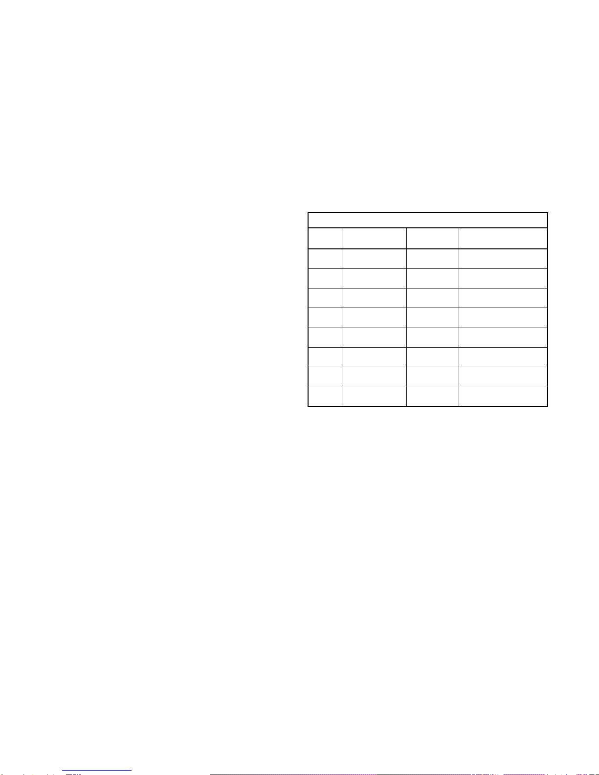
Conditions Chart
RPM Temperature Fan
Status Greasing
Interval
100 Up to 120°F Clean 6 to 12 months
500 Up to 150°F Clean 2 to 6 months
1000 Up to 210°F Clean 2 weeks to 2 months
1500 Over 210°F Clean Weekly
Any
Speed Up to 150°F Dirty 1 week to 1 month
Any
Speed Over 150°F Dirty Daily to 2 weeks
Any
Speed Any Temperature Very Dirty Daily to 2 weeks
Any
Speed Any Temperature Extreme
Conditions Daily to 2 weeks
Inspection
Inspection of the fan should be conducted at the first 30
minute, 8 hour and 24 hour intervals of satisfactory opera-
tion. During the inspections, stop the fan and inspect as
instructed below.
30 Minute Interval
Inspect bolts, setscrews, and motor mounting bolts.
Adjust and tighten as necessary.
8 Hour Interval
Inspect belt alignment and tension. Adjust and tighten as
necessary.
24 Hour Interval
Inspect belt tension. Adjust and tighten as necessary.
Maintenance
Establish a schedule for inspecting all parts of the fan.
The frequency of inspection depends on the operating con-
ditions and location of the fan.
Inspect fans exhausting corrosive or contaminated air
within the first month of operation. Fans exhausting con-
taminated air (airborne abrasives) should be inspected
every three months.
Regular inspections are recommended for fans exhaust-
ing non-contaminated air.
It is recommended the following inspections be con-
ducted twice per year.
• Inspect bolts and setscrews for tightness. Tighten as
necessary. Refer to Torque chart.
• Inspect belt wear and alignment. Replace worn belts
with new belts and adjust alignment as needed. Refer to
Belt and Pulley Installation, page 5.
• Bearings should be inspected as recommended in the
Conditions Chart, page 4.
• Inspect for cleanliness. Clean exterior surfaces only.
Removing dust and grease on motor housing assures
proper motor cooling.
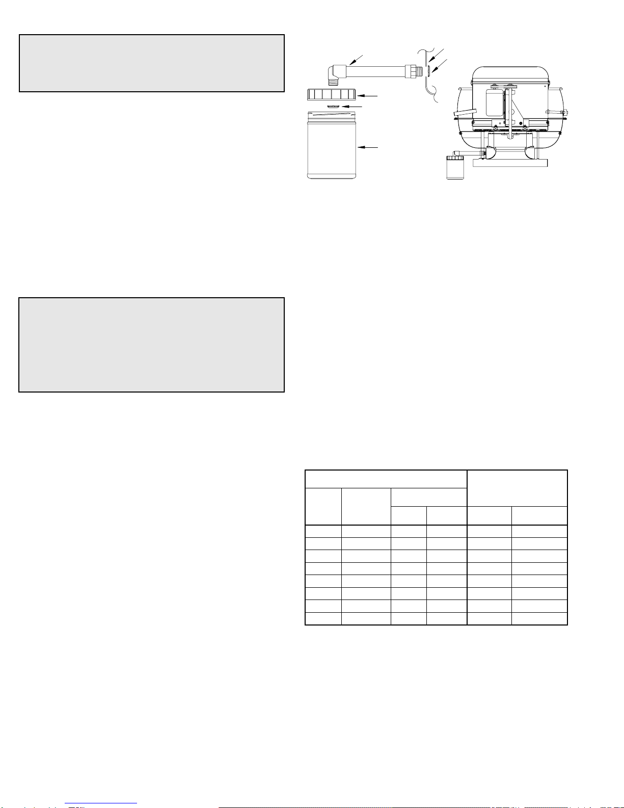
Grease Terminator
Regular inspections of the Grease Terminator 2 are rec-
ommended. Depending on the amount of grease dis-
charged through the fan, the Grease Terminator 2 should
be changed every 30 to 45 days to ensure proper opera-
tion. Any buildup of grease is easily seen during a visual
inspection of the clear canister. However, if the Grease Ter-
minator 2 becomes saturated, grease will no longer be
absorbed.
To replace the Grease Terminator, simply unscrew the
used canister and screw on a new one.
Lubricants
Loren Cook Company uses petroleum lubricant in a lith-
ium base conforming to NLGI grade 2 consistency. Other
grades of grease should not be used unless the bearings
and lines have been flushed clean. If another grade of
grease is used, it should be lithium-based.
A NLGI grade 2 grease is a light viscosity, low-torque,
rust-inhibiting lubricant that is water resistant. Its tempera-
ture range is from -30°F to +200°F and capable of intermit-
tent highs of +250°F.
Motor Bearings
Motor bearings are pre-lubricated and sealed. Under nor-
mal conditions they will not require further maintenance for