Cooke WaterWitch Installation instructions

Product Support Guide
Full Electrical Cerficaon
Inside & Outside use
(ESV160204)
C-Tick Approval
N11116

ii
INTRODUCING THE WATER WITCH
Thank you for purchasing a Water Witch electronic water
leveller. The Water Witch has been Australia’s most trusted
auto leveller for more than 20 years and is a product close to
our heart – it gave rise to our business and established our
reputaon for outstanding quality.
The Water Witch began life during the 1980s as the Neptune’s Mate
automac water leveller. As a pool builder I was frustrated with the poor
quality and reliability of levellers available at the me. Neptune’s Mate
prototypes were developed and tested in my shed at home unl we had a
suitable producon model. Aer a few years of producon, further tweaks
and improvements were decided upon. The Water Witch was born.
For the same reasons I developed the Water Witch, my industry friends
began installing them into their pools and water projects. Its popularity has
since soared and Cooke Industries has evolved from its Cookes Pools & Spas
heritage to become a strong, independent business.
The Water Witch proudly remains Australian made to ensure we control
producon quality and deliver the very best product to you. Thank you
for your support and we trust your Water Witch will deliver many years of
reliable service.
Managing Director

01
INDEX
Compliance noce Page 02
Product applicaons and warnings Page 03
Product components and part numbers Page 04
Control box installaon Page 05
Sensor installaon Page 06
Solenoid installaon Page 08
Alternave installaon opons Page 10
Start-up process Page 12
Test and me delay modes Page 13
Operaon of indicator lights Page 14
Troubleshoong process Page 15
Other faults Page 19
Maintenance & specicaons Page 20
Warranty noce Page 21

02
COMPLIANCE NOTICE
The Water Witch is
approved for use in all
Australian states and
territories. To comply
with Western Australia
Water Authority
regulaons the water
supply side must be
installed as per this
guide, with parcular
aenon given to the
20mm air gap.
The WaterMark is a registered certification trademark of the Australian Building Codes Board (ABN 74 599 608 295). This Certificate of Conformity is
issued for
WaterMark type 1 under arrangement with Australian Building Codes Board.The use of this certificate is subject to the Client complying with
the BSI Terms and Conditions. BSI Group ANZ
Pty Ltd, Suite 2, Level 7, 15 Talavera Road, Macquarie Park, NSW 2113.
The validity of this certificate can be checked at website:
www.bsi-global.com/clientdirectory and the JASANZ website: www.jas-anz.org/register. This
certificate remains the property of BSI and must be returned upon its request. Template updated August 2014.
WaterMark Certificate
Of Conformity
–Level 1
This is to certify that
Nymet Australia Pty Ltd
ABN
Head Office Address
1/53 Stanbel Road
Salisbury Plain
South Australia
5109
Australia
Holds Certificate Number
W4004
Standard
ATS 5200.030:2007 Technical specification for plumbing and drainage
products Part 030: Solenoid Valves
Issue Date
21/09/2015
Is authorised to use the WaterMark
as shown below only on products identified in the referenced Certification
Schedule. Such products have been Type Tested and are manufactured under the Product Certification
Requirements monitored by BSI to ensure that the manufacturing process has the ca
pability to consistently
produce products in compliance with and are certified to the appropriate S
tandard referred to above.
The Licence is granted subject to the rules governing the use of the WaterMark.
For and on behalf of BSI
Marc Barnes
, Managing Director, BSI Group ANZ Pty Ltd
Originally registered
28/03/2012
Latest issue
21
/09/2015
Expiry date
21
/09/2020

03
PRODUCT APPLICATIONS AND WARNINGS
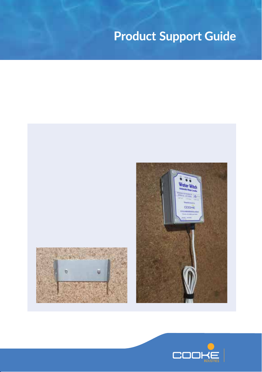
The Water Witch is used in many dierent applicaons and projects to maintain a minimum
water level. Some of the most popular applicaons include:
• Swimming pools and spas •
Balance tanks
• Water features and ponds •
Innity edge troughs
• Water / Splash parks • Commercial pools
• Irrigaon projects • Water tanks
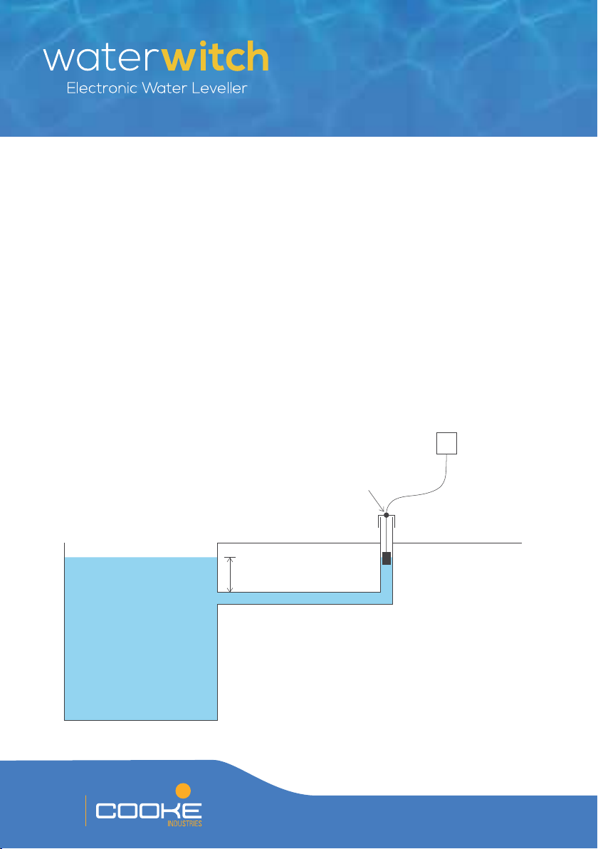
Given the many suitable applicaons for the Water Witch, a quality installaon is required
to ensure performance is not aected by site condions or any other factor.
•
The Water Witch is manufactured
and tested to the highest
internaonal standards. Wear
and onsite condions, however,
may cause component failure. All
installaons must include sucient
overow provisions to ensure a
ooding event does not occur.
• Indoor pools and enclosed projects
must also feature sucient overow
provisions to avoid a potenal
ooding event.
• The Water Witch may not be
suitable for installaons where the
water source is connected to a
pressure pump. Conrm high and
low pressure readings at your site
to ensure the water supply pressure
is always within the unit’s required
operang pressure.
• Contact your local water authority
to conrm whether your proposed
Water Witch supply side installaon
complies with the relevant water
regulaons.
• Individual components may need
to be replaced in the future. All
installaons should incorporate
provisions for easy part replacement.
• The Water Witch includes wearing
components that may fail or be
aected by onsite condions. A
visual inspecon of all components
is required at least every month to
ensure the unit is operang correctly.
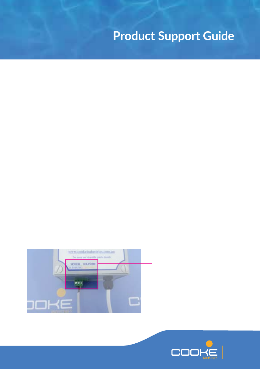
•
The power supply must always be
turned o and the Water Witch
power lead removed from the power
supply if the control box cover is
being removed.
Please note the following important project consideraons:

04
PRODUCT COMPONENTS AND PART NUMBERS
The reliability and durability of the Water Witch is founded on its simplicity – there
are just three main components and the unit will work well if all components are
funconing correctly and site condions are suitable.
CONTROL BOX
WS345 Water Witch Control Box
SENSOR
WS355 Water Witch Sensor Only – 5m
WS356 Water Witch Sensor Only – 20m
WS357 Water Witch Sensor Only – 30m
WS358 Water Witch Sensor Only – 40m
WS359 Water Witch Sensor Only – 50m
WS360 Water Witch Sensor Only – 60m
SOLENOID AND CABLE
WS320 Water Witch Solenoid Only
WS330 Water Witch Solenoid Cable Only
WS335 Water Witch Solenoid & Cable
Note – Special order opons are available for reverse sensors and sensors up
to 250m long.

05
The Control Box is the brain of the operaon. A circuit board within the Control Box
connually receives signals from the Sensor to conrm whether the body of water is at
the required level or if water needs to be added to the project.
CONTROL BOX INSTALLATION
• Posion the mounng bracket at
least 1.2m above ground level and
ensure a consistent power source
is within reach of the Control Box
power lead.
• The Control Box is approved for
indoor and outdoor use. However,
locang the Control Box so it is
protected from the weather will
extend its serviceable life.
• Secure the mounng bracket to the
desired posion on a wall or post
with appropriate screws for the
backing material.
INSTALLATION PROCESS AND CONSIDERATIONS:
• Clip the Control Box into the bracket
where it will be held in place.

06
SENSOR INSTALLATION
The Sensor sits in a balance line, tank or trough to monitor the project’s water level. A ball
oat inside the Sensor lowers as the water level drops, in turn connecng a light beam
between two LED lights in the top of the Sensor. These lights complete an electrical circuit
and the Control Box opens the Solenoid to add water to the project.
As water is added to the project, the water level rises and the ball oat is pushed to
the top of the Sensor. As the ball intersects the light beam at the top of the Sensor,
the Control Box recognises the full water level. Instead of stopping the ow immediately,
the TIME DELAY MODE then overlls the project for a set period as dictated by the
parcular seng.
The Water Witch Sensor is available in standard lengths of 5m, 20m, 30m, 40m, 50m
and 60m. Special order sensors can be manufactured up to 250m long.
Sensor installed in rst balance line
Balance line to be
300mm below water level
Cable gland to
adjust sensor height
Sensor set to
desired level
50mm balance line
Control
Box
Balance line to extend
300mm above water level
DO NOT GLUE
50mm END CAP
POOL

07
INSTALLATION PROCESS AND CONSIDERATIONS:
• Two 50mm class 9 or class 12 PVC pipes are required as balance lines from the project’s
wall to the pump and lter area. One pipe is for the sensor and the second is required
for the ll line back to the pool. ALWAYS USE 50MM PIPE FOR THE SENSOR
HOUSING TO ENABLE ADEQUATE FLOW AROUND THE SENSOR AND FUTURE
SERVICABILITY.
• THESE PIPES MUST BE PLACED AT LEAST 300MM BELOW WATER LEVEL and can
be dressed with push-in eyeballs to match the project’s other wall ngs.
• The pipes are usually run along the sucon and return trench and elbowed up within
the equipment area. THESE PIPES MUST BE LEVEL TO AVOID AIR LOCKS which will
aect ow and performance.
• A 50mm cap is provided to cover the sensor pipe housing and protect the Sensor
from dust, debris, pests and foreign materials. The cap ts neatly onto the 50mm
sensor pipe housing.
• DO NOT GLUE THE CAP TO THE SENSOR HOUSING PIPE.
• If the Sensor is to be located away from the equipment area, ALWAYS RUN THE LEAD
THROUGH ADEQUATELY SIZED CONDUIT THAT WILL ENABLE THE COMPLETE
SENSOR TO BE REPLACED AT A LATER DATE.
• NEVER CUT EXCESS SENSOR CABLE. Roll excess cable and bind together with the
Velcro straps provided.
• INSERT THE SENSOR PLUG
INTO THE CORRECT PORT
ON THE CONTROL BOX AS
INDICATED ON THE LABEL.

08
SOLENOID INSTALLATION
The Solenoid is regulated by the Control Box. When the water level is low the Control
Box sends a 22V DC current to open the Solenoid so water ows in to the project.
The Solenoid will close when the water level is restored to the correct level.
Solenoid cables up to 100m long are available by special order.
INSTALLATION PROCESS AND CONSIDERATIONS:
• The Solenoid ow is one direconal
ENSURE THE SOLENOID
FLOW DIRECTIONAL ARROW
IS POINTED IN THE SAME
DIRECTION AS THE WATER FLOW.
• The Solenoid has a 20mm male
thread on each end. Connect to
PCV or copper couplings and pipe
on the water supply line.
Balance line to be
300mm below water level
50mm balance line
POOL
Solenoid Tap or
Two-way
valve
20mm
supply
line
20mm air gap
Water source
Control
Box
Balance line to extend
300mm above water level
Solenoid installed in second balance line

09
• The solenoid requires an operang pressure range of 29-116 PSI (200-800 kPa).
ENSURE THE ONSITE PRESSURE IS SUITABLE FOR CORRECT OPERATION OF
THE SOLENOID. Install a pressure liming valve on the water supply line if the onsite
pressure is greater than 116 PSI (800 kPa).
•A TAP OR TWO-WAY VALVE MUST BE
PLACED BEFORE THE SOLENOID TO
ENABLE THE WATER SOURCE TO BE
TURNED OFF AT ANY TIME.
• Standard installaon posions the supply line
20mm above the ll balance line without a hard
connecon (An air gap is required to ensure the
water from the project cannot contaminate the
water source). THE FILL FLOW RATE MUST
NOT EXCEED THE RATE THE BALNCE LINE
TRANSFERS WATER INTO THE PROJECT.
• If approved in your local area, the ll line can
be plumbed into the ltraon return line.
If installing in this manner, A BACKFLOW
PREVENTER MUST BE INSTALLED
BETWEEN THE SOLENOID AND THE
WATER SOURCE TAP.
• INSERT THE SOLENOID PLUG
INTO THE CORRECT PORT
ON THE CONTROL BOX AS
INDICATED ON THE LABEL.
20mm
The solenoid is a wearing
component with an indenite
operang life. Your project
should include suitable overow
provision in case of possible
solenoid failure.

10
ALTERNATIVE INSTALLATION OPTIONS
BALANCE TANK
The Water Witch is the most
eecve auto leveller for
balance tank installaons.
Maintaining a minimum
water level in the balance
tank will ensure the pump
and pool equipment is
protected whilst also
allowing for the high water level
uctuaons caused by bather
acvity and excess rainwater.
INSTALLATION CONSIDERATIONS:
• The Sensor should be housed inside 50mm class 9 or class 12 PVC pipe aached to
the wall of the balance tank. Fasten the pipe to the wall with brackets, ensuring there
is enough clearance at the top to aach the Sensor end cap.
• Run the Sensor cable through appropriately-sized conduit to ensure the Sensor can
be accessed for serviceability and replaced if required.
• Small debris capable of aecng sensor performance can build up inside balance
tanks. It is advisable to protect the sensor from small debris by covering it with a
silt sock or stocking. Alternavely, cover the base of the sensor pipe housing with
gauze so debris is blocked while water can sll move freely.
• An overow provision will need to be installed at the maximum water height
inside the balance tank.
Inflow
from pool
Cable gland to
adjust sensor height
50mm PVC pipe
to house sensor
should be aached
to the balance tank
wall with brackets
Control
Box
DO NOT GLUE
50mm END CAP
Gauze covering
base of pipe
BALANCE TANK

11
INFINITY EDGE TROUGH
An innity edge provides pool projects with addional design exibility and creavity.
However, such designs pose addional challenges to ensure the pool operates
eecvely and equipment is protected.
There are two crucial design factors to consider in relaon to the required water level
within an innity edge trough:
• A minimum water depth must be maintained within the trough to ensure enough
water is available to ll the pool and generate an overow into the trough before the
trough runs dry. Failure to do so will most likely result in severe pump, equipment
and site damage.
• The water level in the trough may increase dramacally during a signicant rainfall
event or heavy bather load. The trough capacity above the minimum water level
must suciently allow for this increase.
INSTALLATION OPTIONS:
• This diagram represents the
recommended installaon
layout. Note that onsite
limitaons may not make
this conguraon possible.
• A second opon is to use
the balance tank layout
on Page 10 for installaon
within an innity edge
trough.
At least
150mm
Balance line must
be higher than tank
capacity
Cable gland to
adjust sensor height
Sensor set to
desired level
50mm balance line
Infinity Edge Trough
Minimum
water level
Maximum
water level
Control
Box
DO NOT GLUE
50mm END CAP

12
It’s now me to start your Water Witch. Complete the following process to test your unit
and conrm all components are operang correctly:
STEP 1: Ensure the project is lled to the required water level.
STEP 2: Ensure the sensor and solenoid plugs are connected to the correct ports
of the Control Box (Sensor on the le and Solenoid on the right).
STEP 3: Turn the power and water supplies on and ensure the solenoid ow
direconal arrow is poinng in the same direcon as the water ow.
STEP 4: Li the Sensor from the balance line and hold it upside down to simulate
full water level. The ON and SENSE lights should ash in unison every
2-4 seconds.
STEP 5: Turn the Sensor around the right way up to simulate low water level. The
ON light should connue to ash every 2-4 seconds and the FILL light
should be solid. The Solenoid should also open and add water to the project.
STEP 6: Repeat steps 4 & 5 a few mes to conrm the unit turns on and
o correctly.
STEP 7: Aach the sensor end cap to the sensor balance line and hold the sensor
cable while you loosen the cable gland. Slowly lower the Sensor unl the
water ow stops and the ON and SENSE lights ash every 2-4 seconds.
Re-ghten the cable gland to set the sensor level.
THE SENSOR IS NOW SET AT THE CORRECT LEVEL. COMPLETE STEPS 8-10
ON THE FOLLOWING PAGE TO SET THE CORRECT TIME DELAY MODE.

13
CAPACITY
(LITRES)
SWITCH
1
SWITCH
2
SWITCH
3
SWITCH
4
ADDITIONAL
FLOW
Test Mode N/A UP UP UP UP 2 Seconds
Spa Up to 10,000 UP DOWN UP UP 13 Seconds
Pool 10,000-50,000 UP UP DOWN UP 75 Seconds
Commercial More than 50,000 UP UP UP DOWN 330 Seconds
TEST AND TIME DELAY MODES
The Water Witch features four me delay sengs
that control the length of the FILL cycle. The me
delay slightly lls the pool with addional water to
prevent the Water Witch from connually engaging
and disengaging the FILL cycle. The four me delay
sengs are controlled by the posion of dip switches
inside the boom right corner of the Control Box.
STEP 8: TURN THE POWER SUPPLY OFF AND UNPLUG THE
WATER WITCH POWER LEAD.
STEP 9: Remove the Water Witch Control Box cover and set the Dip Switches to
the correct mode as per the table above.
STEP 10: Replace the Water Witch Control Box cover, plug in the power lead and
turn the power on.
THE WATER WITCH IS NOW SET TO THE CORRECT WATER LEVEL AND TIME
DELAY MODE.
Refer to the following table for the appropriate me delay seng for your project:
If you need to test the Water Witch or any of its
components you must always return the unit to
TEST MODE as per the correct dip switch seng.

14
OPERATION OF INDICATOR LIGHTS
Signal lights on the Control Box conrm its operaonal status and illuminate as per the
following three sequences:
• ON and SENSE lights are ashing in unison every 2-4 seconds – The Water Witch is
sensing the water level and believes it is at the correct height.
• ON light is ashing every 2-4 seconds and the FILL light is solid – The Water Witch is in
TEST MODE and is adding water because it believes the water level is low.
.• ON and FILL lights are solid – The Water Witch is in one of the TIME DELAY MODES
and is adding water because it believes the water level is low. BOTH LIGHTS WILL
REMAIN ILLUMINATED DURING THE TIME DELAY FILL SEQUENCE AND WILL
ONLY RETURN TO SENSE MODE AFTER THE ADDITIONAL WATER HAS BEEN
ADDED.

15
TROUBLESHOOTING PROCESS
If your Water Witch is not operang correctly upon installaon or you suspect a fault aer
years of reliable service, follow the steps outlined below then refer to the table of faults to
idenfy the issue:
Return the Control Box sengs to Test Mode as per the instrucons on Page 13.
ENSURE THE POWER SUPPLY IS TURNED OFF AND THE WATER WITCH POWER
LEAD IS REMOVED FROM THE POWER SUPPLY WHEN REMOVING THE CONTROL
BOX COVER. Refer to the following tables to idenfy the fault being experienced and the
acon required to remedy the fault.
WATER WILL NOT TURN ON:
ON & SENSE Sensor – debris may be
impeding funcon
Remove screws & disc plate
from boom of Sensor. Remove
ball to clean the inside of Sensor
and LEDs
Sensor plug not inserted
correctly into control box
or
Individual sensor wires have
been damaged or removed from
sensor plug
Ensure sensor plug is inserted
into correct port at base of
Control Box, inspect sensor plug
for damage and check wires are
connected as follows:
Sensor may need to be replaced if these acons do not correct fault
YELLOWGREEN
BLACK
RED

16
TROUBLESHOOTING PROCESS
WATER WILL NOT TURN ON:
ON & FILL Water supply is not turned on Turn water supply on
Water pressure is too high Install a Pressure Liming Valve
between supply tap & Solenoid
to reduce pressure
Solenoid has been installed
backwards
Ensure the ow direconal
arrow on the Solenoid is
poinng in the same direcon as
supply ow. Reinstall if required
Solenoid wire is damaged
or does not have a posive
connecon to control box
Ensure there is a solid
connecon for electrical current.
A mulmeter should record 22V
DC at the end of the solenoid
cable and 7-9V DC whilst the
Solenoid is drawing power
Water pressure is too low Supply pressure must be
29-116 PSI (200-800 kPa)
Solenoid may need to be replaced if these acons do not correct
fault

17
ON & SENSE Solenoid – debris may be inside
the solenoid
Unscrew the four screws on
the Solenoid. Remove the body
and diaphragm and inspect for
debris. Clean if necessary
Split diaphragm Open Solenoid and inspect
diaphragm for a split. Replace
Solenoid if required
If no debris or split diaphragm
detected, supply pressure is most
likely too high
Water pressure is too high Install a Pressure Liming Valve
between supply tap & Solenoid
to reduce pressure
WATER WILL NOT TURN OFF:
Be aware there is a ny spring and rod inside the solenoid. Be careful not to lose
those items when removing the top. Take noce of which posion the rod &
diaphragm are in, as incorrect inseron will prevent the solenoid from funconing.

18
TROUBLESHOOTING PROCESS
ON & FILL Sensor plug inserted backwards
or wire in plug is connected
backwards (new installs
generally)
Ensure sensor plug is inserted
into correct port at base of
Control Box and check wires are
connected as follows:
Sensor – debris may be
impeding funcon
Remove screws & disc plate
from boom of Sensor. Remove
ball to clean the inside of Sensor
Sensor or Control Box has failed Return Control Box to Test
Mode and complete the
following to conrm fault:
• Hold Sensor in upright
posion to simulate low water
level
• When water starts owing
remove the sensor plug from
the Control Box
• If water turns o and control
box lights change to ON &
SENSE, the sensor is faulty
• If water connues to ow and
lights on the Control Box are
ON & FILL, the Control Box is
faulty
WATER WILL NOT TURN OFF (CONTINUED):
YELLOWGREEN
BLACK
RED
Table of contents
Other Cooke Water System manuals
Popular Water System manuals by other brands

AdEdge
AdEdge Residential Drinking Water System Installation instructions operations manual

Kärcher
Kärcher WATERCLEAN A 2011201 operating instructions

VERIPURE
VERIPURE VERIPUREVPC5000 owner's manual

GEP
GEP Breaky 1 installation manual

Schwan
Schwan SC60E user guide

HydroTherm
HydroTherm DYNAMIC /X8 installation guide

Wilo
Wilo Actun OPTI-MS Series Installation and operating instructions

Technische Alternative
Technische Alternative FRISTAR3 operating manual

Ecolab
Ecolab Formula1 Installation & operation manual

Tuxhorn
Tuxhorn tubra-PGS XL Assembly and operating instructions

Prozone
Prozone CSS20 owner's manual

SkyJuice
SkyJuice SkyHydrant-GEM user guide