CoolSpace FLURRY CS6-210 User manual

OPERATION AND MAINTENANCE MANUAL
120V/60HZ
FLURRY
CS6210
CS6210HV

IMPORTANT
DO NOT contact the supplier your FLURRY unit
was purchased from. Contact COOL-SPACE with
all warranty and service issues.
COOL-SPACE CUSTOMER SERVICE
800-557-5716
suppor[email protected]

CONTENTS
1.0 INTRODUCTION ..................................................................................1
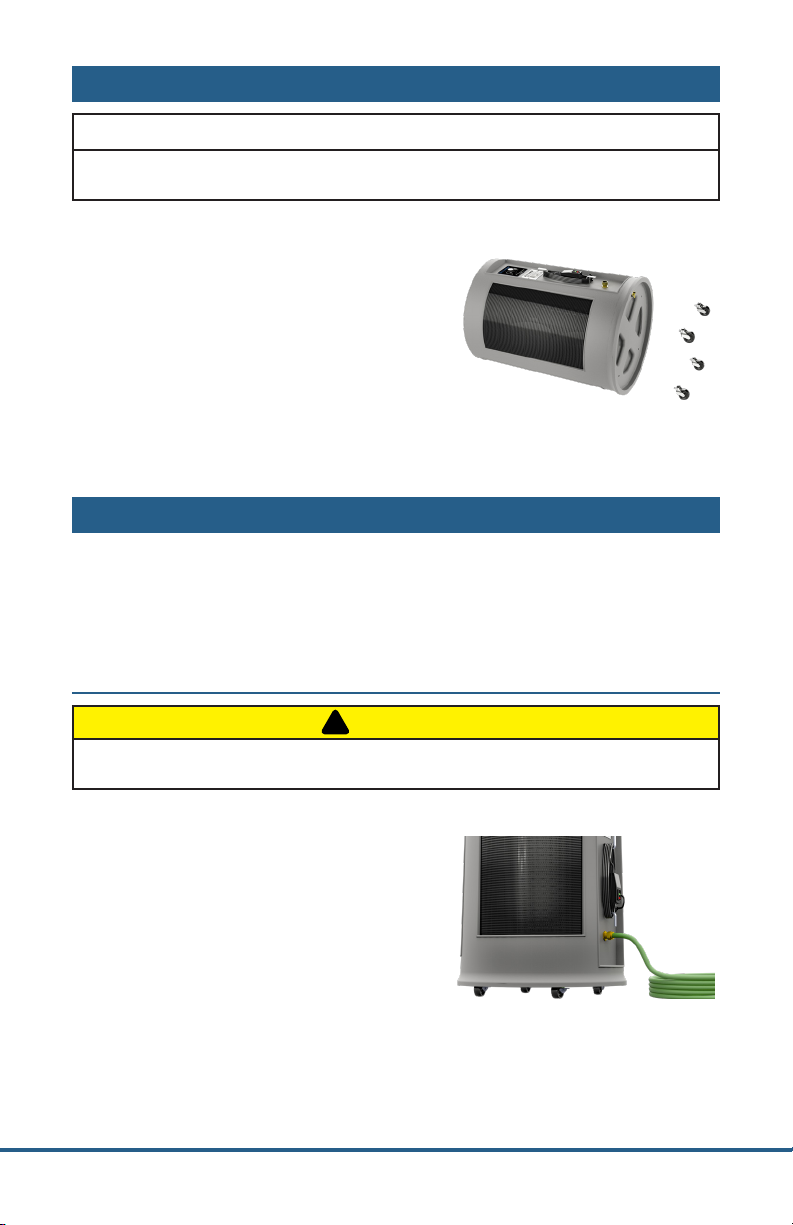
2.0 UNPACKING YOUR FLURRY..............................................................2
3.0 SETUP OF THE COOLSPACE UNIT .................................................2
3.1 Connecting the water supply............................................................... 2
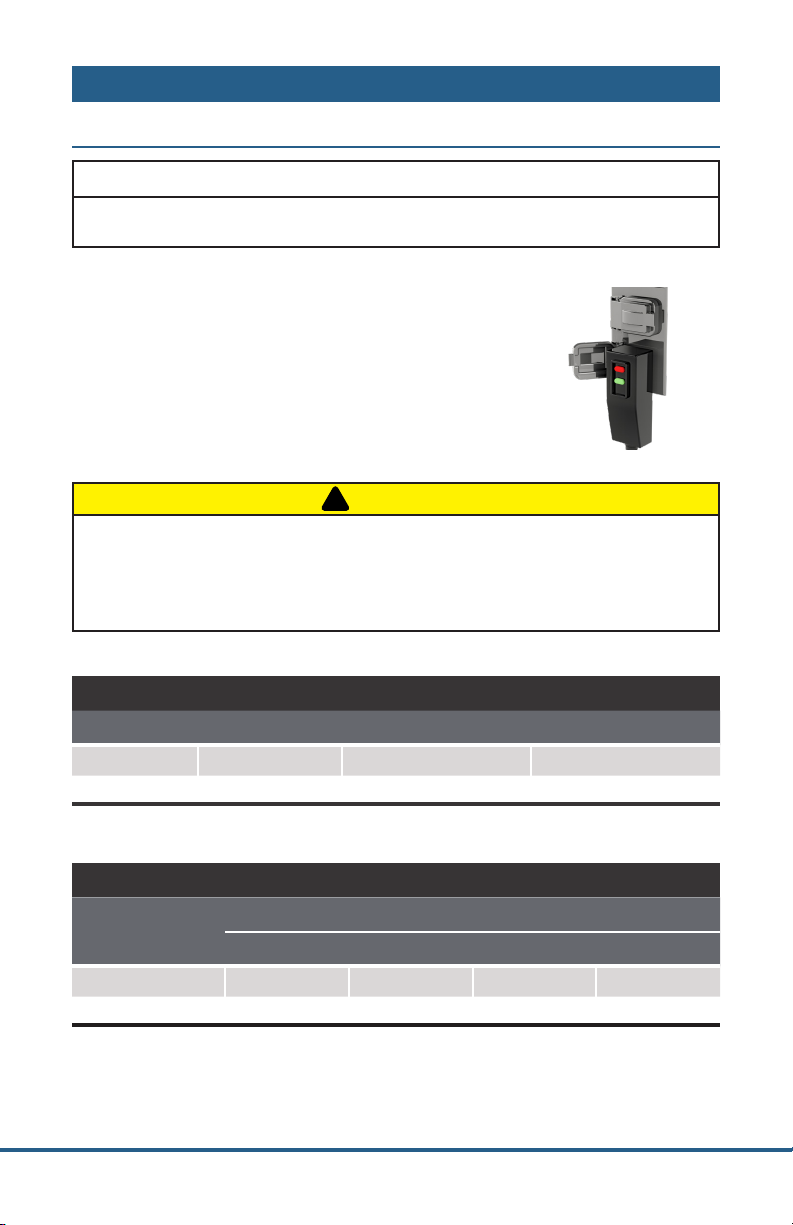
3.2 Connecting the electrical supply ....................................................... 3
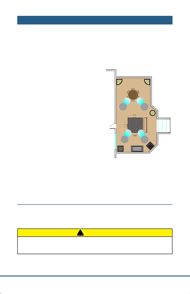
4.0 OPERATING PROCEDURES ...............................................................4
4.1 Filling the unit with water ..................................................................... 4
4.2 Starting the Pump.................................................................................... 5
4.3 Starting the Fan ........................................................................................ 5
5.0 MAINTENANCE AND STORAGE .......................................................6
5.1 Removing the cooling media............................................................... 6
5.2 Daily maintenance................................................................................... 6
5.3 Periodic maintenance............................................................................. 6
5.4 Storage......................................................................................................... 7
6.0 TROUBLESHOOTING/REPAIR...........................................................8
6.1 Troubleshooting ....................................................................................... 8
6.2 Troubleshooting Guides........................................................................ 9
6.3 Fan Repair Procedures.......................................................................... 12
6.4 Pump Repair Procedures..................................................................... 13
6.5 Wiring Diagram....................................................................................... 14
6.6 Technical support .................................................................................. 14
7.0 WARRANTY ........................................................................................15
7.1 Warranty Registration ........................................................................... 15
7.2 Warranty Parts ......................................................................................... 15
7.3 Optional Accessories and Replacement Parts.............................. 15
Due to continuous product innovations, we reserve the right to change
product specication without due notice.

Page 1
SIGNAL WORD DEFINITIONS
!
DANGER DANGER indicates an imminently hazardous
situation which, if not avoided, WILL result in
death or serious injury.
WARNING
!
WARNING indicates a potentially hazardous
situation which, if not avoided, COULD result in
death or serious injury.
!
CAUTION CAUTION indicates a potentially hazardous
situation which, if not avoided, MAY result in
minor or moderate injury.
IMPORTANT
IMPORTANT indicates a potentially hazardous
situation which, if not avoided, MAY result in
property damage.
1.0 INTRODUCTION
COOL-SPACE is a patented and registered Trademark of Hale Industries, Inc.
COOL-SPACE Portable Evaporative Coolers are manufactured by
Hale Industries, Inc.
315 N. Madison Street
Fortville, Indiana 46040
USA
The COOL-SPACE FLURRY and FLURRY-HV are compact, self-contained,
high-efficiency portable evaporative coolers.
FLURRY
The FLURRY unit is designed to have minimal impact visually and maintain
low sound levels to ensure a pleasant ambiance. The FLURRY is uniquely
suited for patios, restaurants and other open-air venues.
FLURRYHV
The FLURRY-HV is designed with high output in mind. Its performance
level makes it better suited for industrial and automotive applications.

Page 2
2.0 UNPACKING YOUR FLURRY
IMPORTANT
Carefully examine the carton for damage before opening. If the carton is
damaged notify the shipping company immediately.
•Find the package of (4) casters
and remove
•Lay box on its side and carefully
open the bottom of the box - DO
NOT STAND UPSIDE DOWN
•Install (4) casters
•Stand unit up on casters and
remove box
3.0 SETUP OF THE COOLSPACE UNIT
The COOL-SPACE FLURRY has been factory tested and is ready to use. The
unit should be placed on a level surface, and the casters locked to prevent
inadvertent movement. Follow instructions below to connect water and
electrical supply.
3.1 CONNECTING THE WATER SUPPLY
!
CAUTION
Do not connect to any water source where water pressure exceeds 120
psi. This will cause permanent damage to the unit.
The FLURRY comes equipped with a
female water source connection. Use a
standard garden hose (not provided) to
connect the water supply to the cooler.

Page 3
3.0 SETUP
3.2 CONNECTING THE ELECTRICAL SUPPLY
IMPORTANT
The COOL-SPACE unit should be plugged into a fused or circuit breaker
protected 15 amp, 120 volt, and 60 Hz circuit.
All models utilize standard 120-volt power supply. The
unit should be plugged into a fused or circuit breaker
protected 15 amp, 120 volt, 60 Hz circuit.
Table 1 shows the amperage requirements for the
specific models. If an extension cord is required, refer
to Table 2 for the proper 3-conductor heavy-duty cord
required.
!
CAUTION
Do not exceed amperage ratings of the extension cord. Undersized
extension cords result in excessive drops in voltage, causing the electric
motor to generate excessive heat. This condition results in inefficient
motor operation and premature motor failure. This will void the
warranty.
AMPERAGE REQUIREMENTS
MODEL VOLTS ± 10% FREQUENCY (Hz) RUNNING AMPS
CS6-210 120 60 1.24
CS6-210-HV 120 60 2.04
Table 1: Electrical Requirements
3CONDUCTOR HEAVY DUTY EXTENSION CORD REQUIREMENTS
LENGTH (Ft) CORD SIZE
16 GA 14 GA 12 GA 10 GA
0-50 13 A 18 A 25 A 30 A
50-100 10 A 13 A 18 A 25 A
Table 2: Cord Size Requirements

Page 4
4.0 OPERATING PROCEDURES
There are 3 factors to consider when determining where to place the
CO O L-SPACE unit.
1. Fresh air supply: The inlet of the unit (mesh sides) require
a constant, uninterrupted supply of fresh air for maximum
performance. A distance of 3 feet clear space to any obstructions at
the rear or inlet side of the unit is recommended.
2. Discharge air ow: The cool air
discharged from the unit should
be free of obstruction to allow
the air to circulate in order to
maximize the cooling zone.
3. Ventilation: In order to operate
at maximum effectiveness, it
is helpful to have provisions to
remove the air discharged from
the unit from the cooling area.
This ensures that the unit does
not recirculate air that has already
been through the evaporative
cooling process.
The unit must be placed on a level surface to operate correctly.
Units create an oval shaped air pattern. Obstacles such as racks and
workbenches may interfere with the air flow. An attempt should be made
to locate the unit in such a manner that interruption of the air pattern is
held to a minimum. Multiple units may be required to cover larger areas.
4.1 FILLING THE UNIT WITH WATER
Once the COOL-SPACE unit has been connected to a water source as
described in 3.1, turn the water supply valve on and the unit will fill with
water. The float valve will shut off the water flow when the sump is full.
!
CAUTION
Prolonged use of hard water without proper water treatment will create
mineral deposit build up causing pump to fail. Failures due to poor water
quality are excluded from the warranty.

Page 5
4.0 OPERATING PROCEDURES
4.2 STARTING THE PUMP
INITIAL STARTUP
On initial start-up the cooling media in your new unit will take a few hours
to become fully saturated. During this time an odor may emanate from
them. This odor will dissipate over time. For best results change the water
in the reservoir a few times.
SUBSEQUENT STARTUPS
On subsequent start-ups turn on the pump, start the fan and cool down.
LOW WATER INDICATOR
The FLURRY is equipped with a low water indicator light.
◊ When the power is on and there is sufficient water in the
reservoir, the light will be lit green, and the pump will be
running.
◊ When the power is on and the water in the reservoir is getting
low, the light will be lit red, and the pump will stop running.
4.3 STARTING THE FAN
Turn the fan control knob clockwise to turn on the fan and adjust the
speed to your preferred setting.

Page 6
5.0 MAINTENANCE AND STORAGE
!
WARNING
ELECTRICAL SHOCK HAZARD
Disconnect the power supply before performing any service or
maintenance. Failure to do so may result in serious injury or death.
5.1 REMOVING THE COOLING MEDIA
In order to perform any maintenance on internal components, the cooling
pads must be removed to access the inside of the unit.
1. Pop pad grilles from support channel.
2. Tilt pads from the top; lift out of the unit.
5.2 DAILY MAINTENANCE
Turn off the pump approximately 15 minutes before the fan is turned off at
the end of each use. This allows the pads to drain and dry out - controlling
mildew and bacteria growth and ensuring long and efficient pad life.
Drain water in the unit if it will be unused for a prolonged period of time.
5.3 PERIODIC MAINTENANCE
The cooling media (pads) acts as a filtering agent and removes dust and
other particles from the incoming air stream. These particles will flow into
the sump and collect there. Water impurities will also collect in the sump
(water treatment tablets available at cool-space.com). In order to keep the
FLURRY operating at peak efficiency you will need to keep the cooling
media and the sump clear of debris.
DRAINING THE WATER SUMP
1. Turn unit off and disconnect the power supply
2. Remove drain plug located at bottom of reservoir; let unit drain
3. Remove cooling pads (refer to section 5.1)
4. Clean out reservoir with either a towel or wet/dry vacuum
5. Reinstall pads and grille
NOTE: Depending on how often you operate the unit, this procedure
should be performed anywhere from every week for heavy use to monthly
for light use.

Page 7
5.0 MAINTENANCE AND STORAGE
5.3 PERIODIC MAINTENANCE (CONTINUED)
CLEANING THE COOLING MEDIA
To keep the COOL-SPACE unit operating at peak efficiency, ensure that the
cooling pads are kept clean and dust-free. Dust and other particles have an
adverse effect on the media’s ability to introduce water into the air stream.
If the pad surface becomes dirty or dusty, clean with a soft brush and
water (never use bleach).
5.4 STORAGE
◊ Remove the pads, as described in section 5.1
◊ Clean with a soft brush and water to remove dust and debris.
◊ Drain sump using procedure described in section 5.3
◊ Wipe dry
◊ Store in a dry area and cover to prevent dust build-up

Page 8
6.0 TROUBLESHOOTING/REPAIR
!
WARNING
ELECTRICAL SHOCK HAZARD
Disconnect the power supply before performing any service or
maintenance. Failure to do so may result in serious injury or death.
!
CAUTION
Please use caution when troubleshooting or repairing all electrical
components. Be certain that all power is disconnected from the unit
before the pads or fan guard are removed to gain access to the fan.
NECESSARY TOOLS
Although the COOL-SPACE unit is designed to be simple to maintain,
it will be necessary to have some basic hand tools - screwdrivers,
pliers, adjustable wrenches, etc. - as well as a volt/ohm meter when
troubleshooting the electrical system.
6.1 TROUBLESHOOTING
The FLURRY consists of three systems:
•Pump,
•Water Distribution System
•Fan System
It is important to determine which system(s) of the unit the problem is
associated with.
When determining which system has a problem, you must define the
associated problem, (e.g. the pump is not running). Several things may
cause this particular problem so carefully check all systems to fully
understand the extent of the problem.
If you have a complete understanding of all of the systems of the FLURRY,
and how they depend on each other, it will be simple to define and solve
any problem.

Page 9
6.0 TROUBLESHOOTING/REPAIR
6.2 TROUBLESHOOTING GUIDES
PUMP
Pump motor will not run when
switch is turned on
Turn fan on to check for power
•If fan doesn’t start check
breaker and cord plug-in
•If fan does start; check for
power to and through pump
switch (when turned on)
Ensure water level is high
enough to make the low- water
cut-o circuit
Fill water reservoir
Pump motor hums when
switch is Turned on, but does
not pump water
Obstruction in impellor
Remove object(s)
Pump motor failure
Replace pump
Breaker trips or fuse blows
when switch is turned on
Check power cord length and
breaker rating
Refer to page (2) for unit
amperage draw and to determine
required cord gauge
Check for locked-up pump
Replace pump
Pump runs but does not pump
water
Air lock in outlet side of pump
Turn off and on to bleed
Ensure the impellor is turning
in pump
If not, replace pump

Page 10
6.0 TROUBLESHOOTING/REPAIR
6.2 TROUBLESHOOTING GUIDES (CONTINUED)
WATER DISTRIBUTION SYSTEM
The water distribution system
consists of two (2) assemblies:
1. The Water Inlet Assembly
•Brass bulkhead fitting
•Float valve assembly
2. The Hose and Valve
Assembly
•Drip Channel
•Valve Assembly
•Connection Hose
Floor at side of unit is wet
Water inlet hose is loose at
supply hose or inlet hose is
loose at bulkhead tting.
Tighten connections and/or
replace hose washers.
Water overflows from reservoir
Float valve hose is loose at
bulkhead tting or at oat
valve.
Tighten connections and/or
replace hose washers
Water pressure is too high to
allow oat valve to shuto
(120psi max)
Reduce water pressure by adding
an inline reducer
Float valve not properly seated
Check all hoses for leaks
Water spitting from the unit
Check The Hose and Valve
Assembly
•Reduce flow control setting
•Replace cracked hose and
valve assembly
•Tighten hose connections
Water leaking from drain plug
Check that plug is tightly
seated in hole
•Tighten drain plug
•Replace drain plug
Too many dry streaks on the
pads
Check for blocked holes in the
drip channel or adjust water
ow
•Remove and clean tube and
holes
•Open water flow control valve
Unit will not fill
Check oat
screen
Clean
Float not
functioning
Replace

Pa g e 11
6.0 TROUBLESHOOTING/REPAIR
6.2 TROUBLESHOOTING GUIDES (CONTINUED)
FAN SYSTEM
Fan won’t run - makes no
sound
Check power cord, extension
cord, switches, circuit breaker
Reconnect power or extension
cord; Reset breaker
Fan won’t run - makes
humming sound
Check Capacitor
Re-center blade hub
Motor stalled (will not turn by
hand)
Replace motor
Breaker trips/fuse blows when
fan starts
Motor stall
Replace motor
Check power source for min.
120 volt/10 amp
Upgrade power supply
Extension cord gauge too small
Replace with heavier cord
Motor overheats, shuts off and
restarts several minutes later
Extension cord gauge too small
Replace with heavier cord
Inlet air obstructed or too close
to wall
Provide minimum 3 feet inlet
clearance
Faulty motor
Replace motor
Fan motor won’t run - switch
makes soft clicking sound
Ensure that switch is making
good contact
Replace switch if needed
Fan blade doesn’t turn - unit
makes squealing sound
Motor stall (will not turn by
hand)
Replace motor
Fan will not reach speed but
turns and makes humming
sound
Check Capacitor (where
visible) and motor electrical
connections
Replace capacitor or motor
Extension cord gauge too small
Replace with heavier cord

Page 12
6.0 TROUBLESHOOTING/REPAIR
6.3 FAN REPAIR PROCEDURES
!
CAUTION
Repairs should be performed by a qualified technician!
!
WARNING
ELECTRICAL SHOCK HAZARD
Disconnect the power supply before performing any service or
maintenance. Failure to do so may result in serious injury or death.
FAN MOTOR REPLACEMENT FOR CS6210 & CS6210HV
1. Remove cooling pads (see section 5.1 for pad removal instructions)
2. Remove the black motor wiring plate and disconnect motor wires.
(Mark each wire with a marker or marker tape to allow for easy
matching when installing new motor.
3. Remove louver
4. Remove the (4) nuts and bolts that mount the motor, fan, and
support braces (complete fan assembly).
5. Replace new fan assembly.
6. Secure with (4) nuts and bolts.
7. Replace any wire ties that were removed when taking out the old
fan assembly.
8. Replace the black motor wiring plate.
9. Reinstall pads and connect power

Page 13
6.0 TROUBLESHOOTING/REPAIR
6.4 PUMP REPAIR PROCEDURES
!
CAUTION
Repairs should be performed by a qualified technician!
!
WARNING
ELECTRICAL SHOCK HAZARD
Disconnect the power supply before performing any service or
maintenance. Failure to do so may result in serious injury or death.
PUMP REPLACEMENT FOR CS6210 & CS6210HV
1. Remove cooling pads (see section 5.1 for pad removal instructions)
2. Remove switch plate and disconnect pump wire (refer to wiring
diagram on page 14).
3. Remove hose and level switch from pump.
4. Remove pump from water sump and install new pump.
5. Reverse the above procedures to reconnect the wiring, lift pump
bracket and reconnect the hose. Secure wires to fan frame with wire
ties to clear the fan blades. Be sure to position the plug correctly.
6. Reinstall cooling pads and guards, reconnect power and test pump.

Page 14
6.0 TROUBLESHOOTING/REPAIR
6.5 WIRING DIAGRAM
6.6 TECHNICAL SUPPORT
Technical support and service are available through the
COOL-SPACE Technical Support Line at:
1-800-557-5716
support@cool-space.com
www.cool-space.com/support
5
1
9
1314
FAN
120V
PUMP
LOW LEVEL
SWITCH
FAN
VARIABLE SPEED
SWITCH
PUMP SWITCH
INDICATOR LIGHT
GREEN
BLACK
BLACK
BLACK
BLACK
RED
BLACK
WHITE
WHITE
BLUE
BLACK
GREEN
WHITE
GREEN
WHITE
WHITE
WHITE
GREEN
GREEN
GREEN
GREEN
WHITE
BLACK
BLACK
BLACK

Page 15
7.0 WARRANTY
The limited warranty is sixty (60) months from date of invoice. Refer to the
manufacturer’s Warranty Policy for details. (Applies to units purchased after
January 1, 2019)
7.1 WARRANTY REGISTRATION
You must register your COOL-SPACE Portable Evaporative Cooler within
fifteen (15) days of initial purchase to validate your cooler’s warranty. You
may register online at www.cool-space.com.
7.2 WARRANTY PARTS
Warranty replacement parts are available through COOL-SPACE. If you have
any questions or concerns, please contact us direct at 1-800-557-5716 or at
sales@cool-space.com. Please have your model number and serial number
ready.
IMPORTANT
DO NOT DISCARD FAULTY PARTS
Check with the Manufacturer they may need to be returned
for warranty credit.
7.3 OPTIONAL ACCESSORIES AND REPLACEMENT PARTS
Accessories and replacement parts are available from your local distributor
or supplier or they can be found online at www.cool-space.com.


CS-MAN-FLURRY60HZ 06242019al
315 N Madison Street
Fortville, IN 46040
317-577-0417 · 800-557-5716
support@cool-space.com
CO O L-SPACE.com
This manual suits for next models
1
Table of contents