4www.cooperbussmann.com/wirelessresources
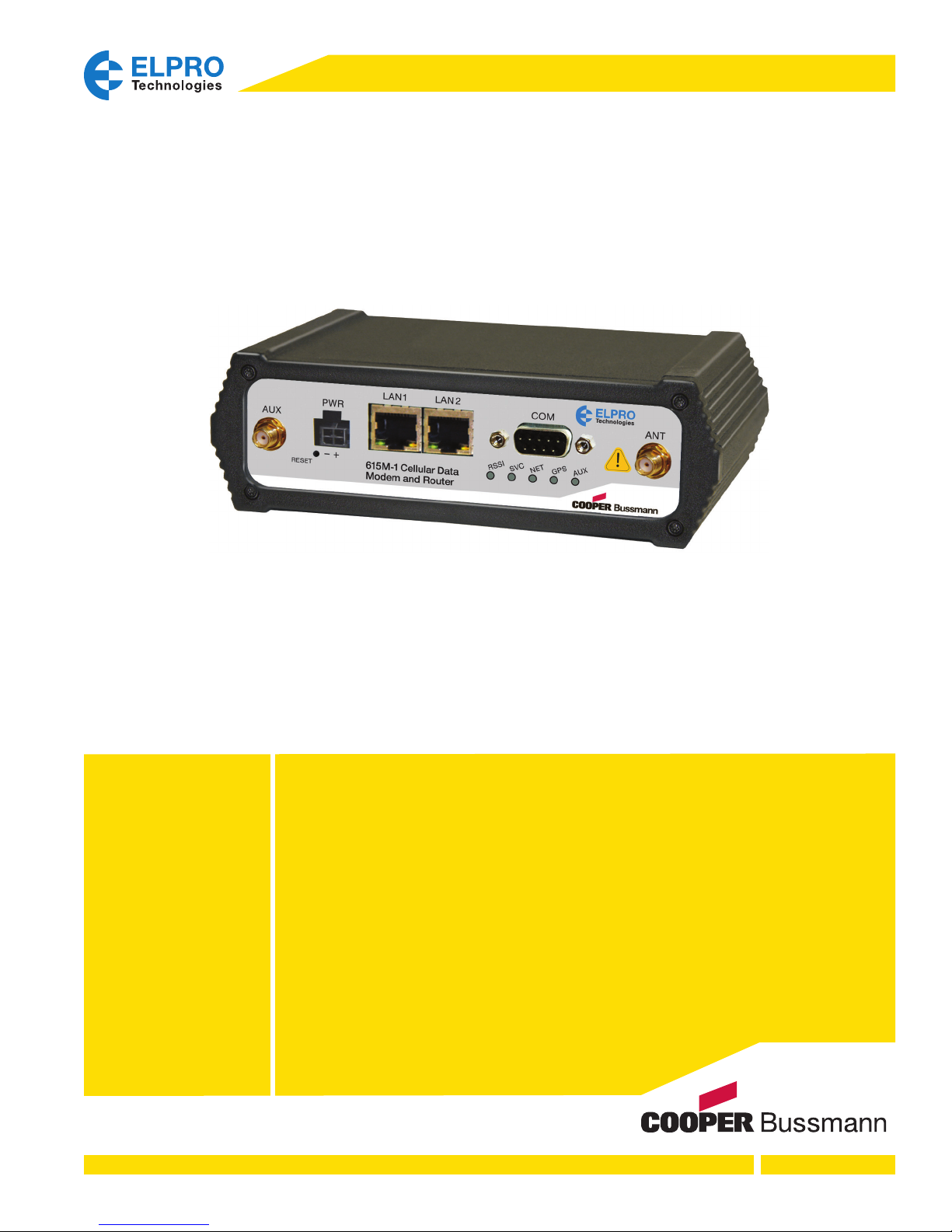
Cooper Bussmann 615M-1 Cellular Data Modem and IP Router Series Manual
Rev Version 1.0
Chapter 1 - INTRODUCTION ...................5
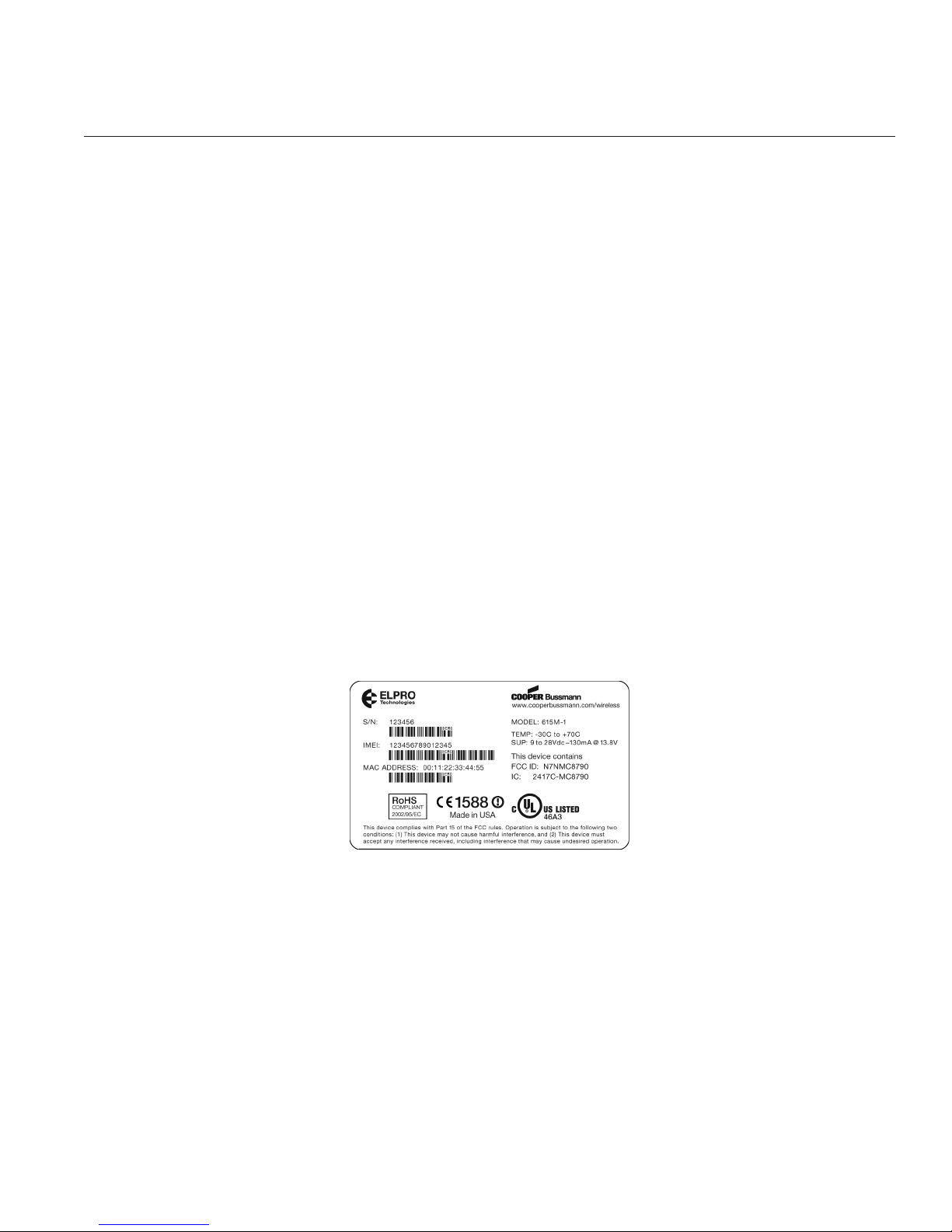
1.1 Module Identification .....................5
1.2 Features and Benefits ....................5
1.3 General Specifications....................6
1.4 Mechanical Specifications .................8
1.5 Order Information........................9
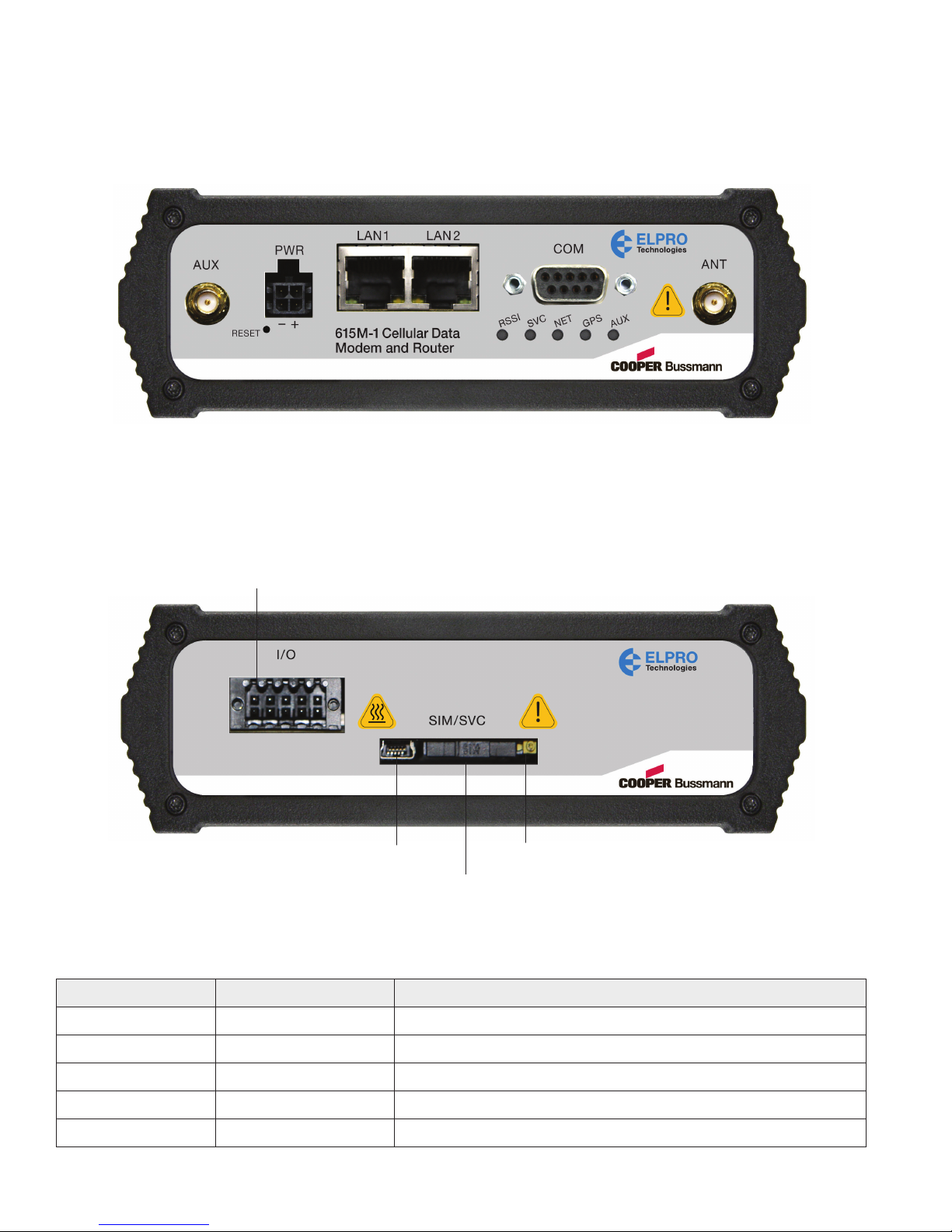
1.6 External Connectors ....................10
1.7 Antenna ..............................11
1.8 Power Cable Pinout ....................11
1.9 RS-232 Serial Port Integration Parameters ..12
Chapter 2 - GETTING STARTED ...............13
2.1 Package Contents ......................13
2.2 Device Connections.....................13
2.3 LAN Configuration ......................14
2.4 Cellular Connections ....................15
Chapter 3 - 615M-1 WEB INTERFACE ..........16
3.1 Logging on to the Web Interface...........16
3.2 Unit Status ............................17
Status ...............................17
Identity ..............................20
Basic Settings.........................20
3.3 Cell Connection – 615M-1................22
Carrier ...............................22
GSM Settings .........................23
CDMA Settings ........................24
System Monitor........................27
Dynamic DNS .........................28
3.4 LAN Settings ..........................30
MAC Filtering .........................33
IP Filtering ............................34
3.5 Router ...............................37
Port Forwarding .......................37
Static Routes .........................38
3.6 Security ..............................39
PPTP ................................40
IPsec ................................41
GRE.................................44
3.7 Serial ................................44
External Serial .........................44
3.8 Diagnostics ...........................48
SNMP ...............................48
Logging ..............................50
3.9 I/O Settings ...........................51
Status ...............................51
Settings..............................52
Labels ...............................56
3.10 Firmware Update ......................56
Chapter 4 - IP ADDRESSING..................58
4.1 Overview .............................58
4.2 IP Addressing Tutorial ...................58
4.3 Private vs. Public IP Addresses............58
4.4 Port Forwarding ........................59
4.5 DMZ .................................59
4.6 Friendly IP Address .....................60
Chapter 5 - IPSEC AND VPN PASS-THROUGH
DEPLOYMENT GUIDE .......................61
7.1 Benefits of IPsec .......................61
7.2 615M-1 Configured IPsec Client ...........61
Cisco Router–VPN Server Configuration ....62
615M-1–IPSEC Client Configuration .......62
7.3 615M-1 Configured VPN Pass-through......63
615M-1–VPN Pass-Through Configuration ..64
Chapter 8 - USER I/O PORT ..................65
8.1 Circuit for Analog Inputs .................66
8.2 Simplified Circuit for Digital Input/Outputs ...66
8.3 Simplified Circuit for Mechanical Relays .....67
8.4 Inserting Wires into User Port Connector ....67
Appendix A - GLOSSARY ....................68
CONTENTS