04649-1098<90-00194> PAGE 9
3. Action: Apply power to the shelf.
4. Action: Connect a Transmit Measuring Set (TMS) to the XMT
LINE jack of the 44202 modem. Configure the TMS for 600 ohm ter-
minated measurement.
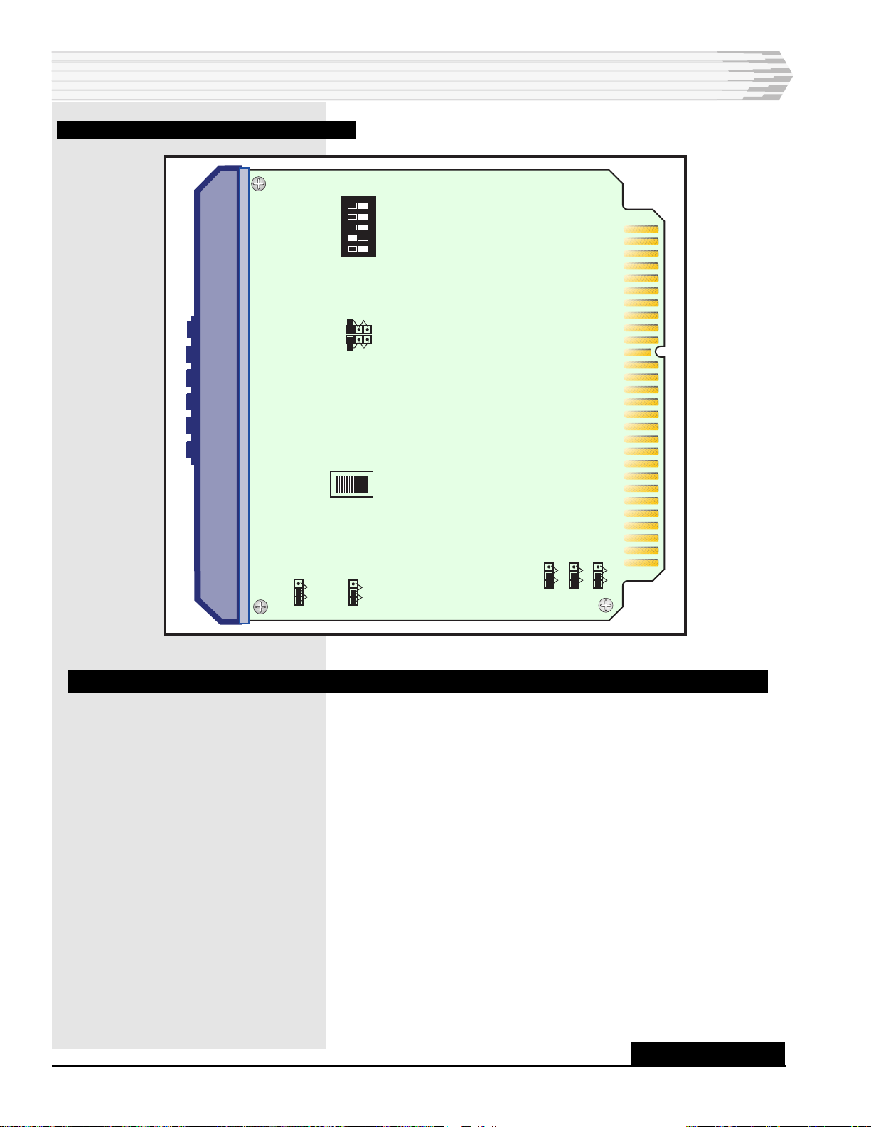
5. Action: Place the TEST switch, on the 44202 modem, in the ON
(up) position.
Result: The RTS and DTR LEDs light. A 1200 Hz tone is trans-
mitted to the test set.
NOTE: Failure to achieve the desired result indicates lack of power or a
defective module.
6. Action: Adjust the XMT LEVEL potentiometer to obtain a reading
of -6 dBm. (Turn clockwise to raise the level; counterclockwise to
lower the level.)
NOTE: If the transmit level cannot be reached, place the XMT GAIN
jumper on the 44202 to HIGH. If the level still cannot be
reached, the module is defective and should be replaced.
7. Action: Move the TMS cable to the 4003C XMT OUT jack.
8. Action: Adjust the 4003C XMT pad switches (located on the front
panel) to obtain the engineered data level.
9. Action: Connect the TMS send jack to the 4003C RCV IN jack. Set
the TMS to send the engineered data level (13 db below tone level).
10. Action: Connect the TMS rcv jack to the 4003C RCV OUT jack.
11. Action: Adjust the 4003C RCV pad switches (located on the front
panel) to obtain a reading of -15 dBm on the TMS.
12. Action: Connect the TMS (set for bridging reading) or db meter to
the test points labeled RCV and GND.
Result: The CD LED lights.
13. Action: Adjust the RCV GAIN pot to achieve a -20 dBm reading in
the TMS.
NOTE: If the receive gain cannot be adjusted, the module is defective
and should be replaced.
14. Action: Disconnect the TMS and place the TEST switch in the OFF
(down) position.
15. This completes the DST alignment. Connect an RS-232 cable from
the GTP to C1 of the DST shelf and remove the termination or open
plug in the transmit path to the existing circuit.
INSTALLATION