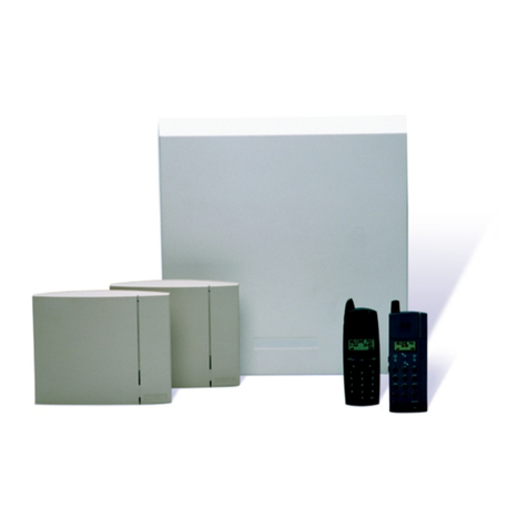
Cooper Security SD3 User manual

Page i
SD3 Speech Dialler
Installation Guide
Issue 2
OP1
OP2
3
6
9
ESCENT
Clear
2
5
8
0
1
4
7
def
mno
wxyz
abc
jkl
tuv
ghi
pqrs
GSM +24°C
12:00 01Jan13

Page ii
Contents
Introduction...........................1
General..............................................1
Specifications......................................2
Connection Types And Standards ..........2
Keys And Displays ...............................3
PCB Connectors And Switches ...............3
Control Panel (SELV) Connections..........4
+12V & 0V .......................................4
Trigger Inputs (A To H) ......................4
Tamper ............................................4
OP1 To OP4 ......................................4
Installation ............................5
Using Pay As You Go Accounts ..............5
Siting Speech Dialler And Antenna.........5
Checking Network Signal Strength.......5
Dealing With Poor Signal Strength .......6
Fitting The Speech Dialler.....................6
Fitting The SIM Card ..........................6
PSTN Module Installation......................7
Commissioning ......................9
To Prompt A Factory Reset ...................9
To Change The Display Language ..........9
Entering The Programming Menu...........9
Leaving The Programming Menu............9
To Register Your SIM Card.................. 10
O2................................................. 10
T-Mobile......................................... 10
Orange........................................... 11
Vodafone........................................ 11
Using Top Up Cards ........................... 11
Programming Options List ...12

Page 1
Introduction
The SD3 Speech Dialler provides a
means of communicating information to
fixed and mobile telephones. You can
either connect the unit to an alarm
control panel (taking advantage of its
power supply and battery backup) or
use the SD3 in a standalone role.
This Guide shows you how to physically
install the speech dialler, and register
the unit with a network provider. The
Guide also shows you how to add a
PSTN module if you wish to connect to
the wired telephone network. For
details of programming the unit please
read the SD3 Programming and
Operating Guide, available at
www.coopersecurity.co.uk.
PLEASE NOTE:
This product is designed to use the
GSM system for its primary
communications. If you do not fit a
GSM SIM card then the speech dialler
will not accept incoming calls for
remote access.
General
The speech dialler is designed to
connect to an intruder alarm control
panel or similar.
The unit requires a power input (from
an alarm control panel or separate
power supply) of between 12V and
28V, with a supply capability of 200mA
or greater.
The speech dialler has a built-in GSM
module that operates with the mobile
telephone network. The unit is not
locked to any mobile phone provider,
and can accept normal SIM cards.
The PSTN module comes supplied with
a 2-metre telephone lead, which plugs
directly into any standard BT socket.
When using the PSTN module Cooper
Security recommends that you site the
unit as near to a BT telephone socket
as possible. If this it not possible you
should either obtain an approved BT
extension lead or permanently wire the
unit to the BT socket (see ‘Connections
to the telephone line’).

Page 2
Specifications
Supply voltage:
12 - 28VDC
Current
consumption
(@12VDC):
50mA (Standby),
170mA (Active)
Trigger Inputs:
Eight:
positive/negative
applied or
positive/negative
removed (5 -
24VDC)
Outputs:
Four open collector
switched -ve
@100mA
Telecommunica
tions Approval:
CTR21
PSTN Module
REN Rating:
1
PSTN Module
Dialling
Formats:
DTMF
Dimensions:
140mm x 115mm x
30mm
Weight:
360g
(approximately)
Operating
environment:
-10oC to +55oC
Connection Types And
Standards
All connections on the speech dialler
are Safety Extra Low Voltage or SELV
(SELV).
The PSTN module contains a mixture of
alarm system-related connections and
telecommunication connections. The
alarm-type connections are Safety
Extra Low Voltage or SELV, while the
telecommunication connections are
called Telecommunications Network
Voltage or TNV.
Note: It is vitally important that the
two types of connections are kept
separate and only linked to appropriate
external alarm systems and telephone
connections, respectively.
TNV circuits should only be connected
by a qualified person in accordance
with local regulations.

Page 3
Keys And Displays
1. Two-line backlit LCD
display
2. Keypad
3. Red indicator shows
the status of Output 1
4. Green indicator
shows the status of
Output 2
Keypad function keys
A Scroll up
B Record / special
character key
CScroll down
DClear display
EEnter / Play
FEscape
PCB Connectors And Switches
1. SIM card holder.
2. Antenna connector.
3. Back tamper switch.
4. PSTN module sockets.
5. Trigger inputs G-H,, power & outputs.
6. Sounder/loudspeaker.
7. Trigger inputs A-F & and tamper wiring.
8. Microphone.
OP1
OP2
3
6
9
ESCENT
Clear
2
5
8
0
1
4
7
def
mno
wxyz
abc
jkl
tuv
ghi
pqrs
GSM +24°C
12:00 01Jan13
1
2
1
2
3
4
5
7
6
8
3
4

Page 4
Control Panel (SELV)
Connections
Before making any connection to the
speech dialler isolate ALL power from
the control panel (mains and battery).
Do not continue if there is power
still present on the control panel.
+12V & 0V
Connect these terminals to the 12V
auxiliary power supply of the alarm
control panel or to a stand-alone power
supply, if necessary.
Trigger Inputs (A To H)
Connect these terminals to the relevant
outputs on the alarm control panel.
When an alarm panel triggers an input,
the unit initiates the calling sequence
and plays the relevant speech and/or
text message. The diagrams below
show the various wiring options for the
trigger inputs.
Note: All inputs must use the same
trigger input polarity. The chosen
polarity is be selected within System
Options > Trigger Polarity.
Trigger input connections for positive
operation
Normally open
loop
to 12V
supply
normally closed
loop
to 12V
supply
Trigger input connections for
negative operation
Normally open
loop
to 12V
supply
normally closed
loop
to 12V
supply
Tamper
These terminals provide tamper
protection for the speech dialler and
should be connected to the auxiliary
tamper circuit on the alarm control
panel.
OP1 To OP4
Four programmable switched negative
@100mA outputs.

Page 5
Installation
Before installing the speech dialler,
please consider the type of network
account and the physical location of the
unit and its antenna.
Using Pay As You Go Accounts
Your speech dialler may not send calls
very frequently. If you decide to use a
Pay As You Go account, then check
with the provider how they deal with
accounts that are quiet for several
weeks or months. (Some providers
close down accounts that do not make
any calls within a set period.) If
necessary you can program the unit to
make a test call at fixed periods.
In addition, the speech dialler can also
forward incoming text messages it
receives warning of low credit.
See the speech dialler Programming
and Operation Guide for details.
Siting Speech Dialler And
Antenna
If you are fitting a speech dialler in
order to use the mobile phone network
then before installing the unit you must
decide on a suitable location.
The unit itself should be in a place that
is convenient for the end user as well
as any wiring. In addition you must site
the antenna so that it can receive a
good signal from the phone network.
Note that the antenna lead is 3m long
Checking Network Signal Strength
There are three ways to check the
network signal strength at your
installation:
1. You can use your mobile phone,
provided that it is registered with
the same network as the SIM that
you intend to fit to the speech
dialler. If your phone reports at
least three bars of signal at the site
of the speech dialler antenna then
the speech dialler should be able to
work on that network.
NOTE: When testing the signal
strength you must hold your phone
in the exact location of the speech
dialler antenna.
If you decide that a location has a good
signal, then you must fit the centre rib
of the antenna within 20mm of the spot
occupied by your phone. (The signal
wavelength is so short, that moving
80mm can change the signal strength
markedly. This may not matter with a
strong signal, but with a weak signal it
could mean that the speech dialler will
not register.)
2. If your phone does not work on the
same network as the SIM you intend
to install in the speech dialler, then,
provided your phone is not locked,
you can put the speech dialler SIM
in your phone, and test for network
signal strength as described in step
1. Ensure that you can make a call
from the chosen position, it is not
enough to rely on the signal
strength indication.
Once you have completed testing
you must remember to shut down
your phone in the recommended
manner before extracting the
speech dialler SIM. If you remove
power abruptly (for example by
taking the phone battery out) the
SIM card may not have time to de-
register from the network, and
some networks may lock out the
SIM for several hours.
Note: Do not lock the SIM card with a
PIN (the speech dialler will not let you
key in a PIN for the card).
3. Use the speech dialler. You can
temporarily fit the SIM card and
antenna to the speech dialler and
power the unit from a 12VDC
battery (see page 7).
You can then register the SIM card (see
page 10). Note that unless the SIM is

Page 6
registered, the speech dialler will
report the strength of the strongest
network signal. This may be an
emergency network. (In the UK, all
networks must provide access to
any mobile phone for emergency
calls.) Check that the unit is
registered before checking the
signal strength.
Dealing With Poor Signal Strength
If the signal strength is poor, either:
Find a better antenna position.
Change the network provider.
Fitting The Speech Dialler
Note: Do not fit the speech dialler OR
its antenna until you have confirmed
that there is adequate network signal
strength.
1 Separate the cover from the base by
using a screwdriver to carefully push
two of the retaining clips (top or
bottom) inwards from the base
indents.
2 Remove the cover assembly and
store in a safe place.
3 Hold the base in position (keyhole to
the top) and mark the three
securing holes. Remove the base
then drill and plug the holes.
4 Pass all cables into the base,
including the antenna lead,
through the cable entries and then
secure the base to wall.
Fitting The SIM Card
1. Fit the SIM card into the SIM holder
as shown here. Double check that
you have fitted the SIM card in the
correct orientation.
1. Connect the antenna to the antenna
input socket.
2. Using the supplied surface wipe,
clean the area onto which you
intend to stick the antenna. Remove
the backing paper on the glued side
of the antenna. Fix the antenna onto
the cleaned surface. Note: The
adhesive on the antenna is fast
acting. You will not be able to
reposition the antenna once you
have put it in place.
3. Connect power, input and output
wiring (see page 5).
4. Reattach the speech dialler cover
assembly onto the base and re-fit

Page 7
the two screws holding the case
together. PSTN Module Installation
The PSTN module is a plug-in board for
the speech dialler that allows it to
communicate via a wired telephone
network.
This section provides brief instructions
on fitting the PSTN module within the
speech dialler. To program the speech
dialler to use the PSTN module, please
see the SD3 Programming Guide.
CAUTION: Remove all power from the
speech dialler before attempting to fit
the PSTN module.
To Install The PSTN Module
1 Unpack the PSTN module.
2 If necessary, remove the speech
dialler unit from the wall fixings and
remove the two screws holding the
front panel and backbox together.
3 Separate the speech dialler front
panel and backbox, and disconnect
the power connection and the siren
lead (if fitted).
4 Thread the telephone cable through
a suitable cable entry hole in the
backbox.
5 Fit the plastic standoff to the PSTN
module (see digram). Remove the
protective strip from the adhesive
base of the standoff
6 Fit the PSTN module to the sockets
on the speech dialler circuit board.
Ensure that the base of the standoff
adheres to the SD-GSM circuit
Telephone cable
terminals (TNV).
Connector pins
(SELV)

Page 8
board. Also ensure that the tamper
spring from the speech dialler can
pass freely through the hole
provided in the PSTN module.
7 Connect the telephone cable to the
telephone cable terminals (TNV) on
the PSTN module.
The easiest way to connect the PSTN
Module to the telephone line is to use
the telephone lead that is provided with
the unit as shown below
However, if the lead is not long enough
or a serial connection is required the
speech dialler can be hard wired to the
telephone socket as shown below:
8 Feed the telephone cable around the
top and side of the module.
9 Re-connect all previously removed
connections (including power).
10 Re-attach the front panel onto the
base and refit the two screws
holding the case together.
3
2
1
6
5
4
A
B
A1
B1
Cable type
1/0.5 CW1308
BT Master Jack (NTE5)
User accessible connections To other telephone
extension sockets
Red
White

Page 9
Commissioning
When beginning a new installation, it is
advisable to prompt the speech dialler
to make a factory reset in order to
ensure that any existing settings are
removed.
To Prompt A Factory Reset
1 Press and hold 9and reconnect
the power to the speech dialler. The
unit will display the factory-reset
menu:
Factory Reset?
[ENT] or [ESC]
At this point:
•Press Eto revert to factory
settings and show the C h a n g e
L a n g u a g e screen:
Change Language?
[ENT] or [ESC]
•Press Fto cancel the factory
reset. The display will change to
standby mode:
GSM +29ºC
12:07 01Jan13
Note: Without a PSTN module the
standby mode screen shows “GSM” and
the temperature on the top line. When
a PSTN module is fitted the standby
screen shows “GSM/PSTN” and the
temperature on the top line.
To Change The Display
Language
1 Following a factory reset, press E
to display:
Change Language?
[ENT] or [ESC]
2 Press Eto display:
¬¦ Ent to Select
[ENT] or [ESC]
3 Use the Aor Cscroll keys to select
the language you want to use.
4 Press Eto select. The speech
dialler will change the display to the
selected language, and enter
standby mode, showing the time
and date, for example:
GSM +29ºC
12:07 01Jan13
The unit is now ready for programming
and testing.
Entering The Programming
Menu
1 From standby, enter the user code
(the default code is 1234). When
you enter the correct code, the
bottom line of the display will show
the first item from a menu of ten
programming options:
¬¦ Ent to Select
Contact Details
To scroll up and down through the
programming menu press the scroll
keys (Aor C). To jump directly to an
option press the relevant hot key. For
example, to display the log option
press 9.
When using the programming menu,
the speech dialler’s trigger inputs are
disabled and therefore the unit will not
call out in the event of an alarm.
Note: For correct operation you must
leave programming as described below.
Leaving The Programming
Menu
1 From within the programming
menu, press Frepeatedly until
the display shows:

Page 10
Press [ENT]
To Leave Menus
2 Press Eto leave the programming
menu and return to standby. If you
wish to remain within the
programming menu, press E.
After you have programmed and
tested the speech dialler, secure the
front cover with the screws and caps
provided.
To Register Your SIM Card
Once you have fitted a SIM card, you
must register the SIM card with the
service provider. To do this you must
make a telephone call from the speech
dialler.
1 Apply power to the unit.
2 From standby, enter the user code,
then use the scroll keys (Aor C) or
0to display the T e s t O p t i o n s
menu:
¬¦ ENT to Select
Test Options
Press Eto select. The screen will
show the first option: T e s t
Messages.
3 Press Cor press 6to show: G S M
P h o n e U t i l s .
4 Press Eto select. The screen will
show the first option: Make Call.
5 Use the scroll keys (Aor C) and
then E, to select the following
options:
M a k e C a l l
Allows you to enter a
number and make a call
via the GSM link. The
speech dialler will act like
a hands free mobile
phone.
S i g n a l
S t r e n g t h
If the level is low you
may need to reposition
the control unit, or seek
another service provider.
G S M
N u m b e r
(This may not appear if
you are using Vodafone
as a service provider.)
Note this number down
so that you can supply it
when registering your
SIM card.
I M E I
N u m b e r
You should note this
number down as you will
need to provide it when
you register your SIM
card with certain service
providers.
6 Select the M a k e C a l l option.
7 Dial the appropriate telephone
number for registering the SIM card
as shown in the instruction leaflets
for the card.
Note that the speech dialler cannot
support the text message response
service calls using the * and # keys.
You must call the service provider
manually and either register with a
human operator, or navigate an
automated answering service.
The exact details of registering your
SIM card differ for each provider. The
following sections show hints for the
main providers.
O2
Note that 02 print the SIM serial
number and the GSM telephone
number on the packing for the SIM
card.
To register an 02 SIM dial 248 and
follow the instructions given by the
automatic answering service.
T-Mobile
T-Mobile print the GSM telephone
number, PIN number and PUK (unlock
number) on the sheet carrying the SIM
card and top up card.
To register a T-Mobile SIM dial 150 and
follow the instructions given by the
automatic answering service.
If you have several mobile phones fix
the sticky label provided showing the
GSM number to the top up card.

Page 11
Orange
Make sure you have the speech dialler’s
IMEI number to hand. You will also
need the SIM card serial number which
is printed on the SIM card.
You will need to provide a password
and the four digit code to identify
yourself in the future. Choose them
before making the call and write them
down in the booklet.
To register an Orange SIM dial 0800
079 0006. A human operator will reply.
While registering your SIM, the
operator will provide you with your
GSM number. Make sure you note this
number on the top up card.
Vodafone
To register a Vodafone SIM dial 2345
and follow the instructions given by the
automatic answering service. During
the instructions you will be given your
GSM number. Make sure that you note
this number down on the back of the
top up card.
Using Top Up Cards
Various service providers supply top up
cards with their SIMs. Part of the
registration procedure is to link the top
up card with the SIM. The cards contain
just enough credit to allow you to make
the registration call. Once you have
finished this process you will need to
supply more credit to the top up card.
You should do this immediately.
While registering, make sure that you
write the phone number of the speech
dialler down on the top up card.
The table below provides spaces for
you record the relevant information
about your GSM installation.
IMEI No. ..........................................................................
SIM Card Serial No. ...........................................................
GSM No. ..........................................................................
Top Up Card No. ...............................................................

Page 12
Programming Options List
1Contact Details
1Contact 01 Name
2Contact 02 Name
…
0Contact 10 Name
2Messages
1Voice Message
1Voice Alarm A
…
8Voice Alarm H
9Voice Restore A
C …
C Voice Restore H
C Voice Site
2Text Message
1Text Alarm A
…
8Text Alarm H
9Text Restore A
C…
CText Restore H
CText Site
3Inbox
1View Messages
2Delete Inbox
3System Options
1Trigger Polarity
CNegative
CPositive
2Remote Options
1Remote Access
2Rings to Answer
31 Ring Answer
3Display Options
1Flash on Message
2Beep on Message
3Temp Display
4Line Fault
4Alarm Levels
1Temperature High
2Temperature Low
3Supply Low
4Signal Low
5Record Options
1Long Play
2Auto Record
6Report Options
1Auto Reporting
2Report Time
Time
Day
Interval
3Omit 1st Digit
7Line Priority
CPSTN Only
CGSM Only
CPSTN first
CGSM first
8Change Language?
CEnglish
CDeutsch
CFrancais
C Nederlands
C Dansk
CItaliano
C Polish
9Daylight Saving
On
Off
4Access Codes
1Edit User Code
2Edit Remote Code
5Ack & Abort
1Abort Options
None
Passcode Only
Code or Restore
Restore Only

Page 13
2Clear by Options
Anyone
No One
6Outputs
Output 1
OFF
Message Waiting
Remote Access
Temperature High
Temperature Low
Listen Active
Speech Active
Phone Line Fault
PSTN In Use
GSM In Use
Call Active
Call Successful
Call Failed
Remote Control 1
Remote Control 2
Remote Control 3
Remote Control 4
Supply Volts Low
GSM Signal Low
Output 2 as for Output 1
Output 3 as for Output 1
Output 4 as for Output 1
7Call Routing
1Trigger Alarm
Route A Alarm To
Route B Alarm To
…
Route H Alarm To
2Trigger Restore
Route A Restore To
Route B Restore To
…
Route H Restore To
3Auto Report
Route Auto Rep. To
4Text Forward
Route Text Forward To
8Date & Time
Enter New Date
Enter New Time
9View Log
(Afor newer, Cfor older)
0Test Options
1Test Messages
Send Alarm A To
…
Send Alarm H To
Send Restore A To
…
Send Restore H To
2Test Outputs
(press 1 to 4 to activate
outputs)
3Test Triggers
(activate each input in turn)
4Test Line
5Test Supply
6GSM Phone Utils
1Make Call
2Signal Strength
3GSM Number
4IMEI Number
5IMSI Number
6Module Type
7Call Provider
7Software Version

Page 14
This product complies with the
1995/5/EC R&TTE Directive.
For further details, please see:
www.coopersecurity.co.uk
© Cooper Security Ltd. Aug 2013
Part Number 12362152 29/4/13
Other manuals for SD3
1
Table of contents