Cooper Tools Cleco SBA-12 Installation and operating instructions

1
Operation & Service Manual
823185 12/02
Balance Arms
12
18
24
30
12
18
24
30
Arm Extension:
Adjustable Arm Extension:
XX
CS Cylinder Single Arm
S Spring Single Arm
CP Cylinder Parallel Arm
SP Spring Parallel Arm
BA
Series:
BA - XX - XX
XX
Mount:
Post
Adustable HeightAH
M Manifold
SM Swivel Manifold
P Parallel
EP Estension Parallel
SS Swivel Small
SL Swivel Large
Wall Mount
WM
Tool Holder:
XX--
NORTH AMERICA
For additional product information visit our website at http://www.clecotools.com
EUROPE
CooperTools
P.O. Box 1410
Lexington, SC 29071
Cooper Power Tools GmbH & Co.
Postfach 30
D-73461 Westhausen

2
For your safety and the safety of others, read and under-
stand the safety recommendations and operating instruc-
tions before operating any power tool with this balance
arm.
Always wear protective equipment:
For additional information on eye protection and face
protection, refer to Federal OSHA Regulations, 29 Code
of Federal Regulations, Section 1910.133., Eye and Face
Protection, and American National Standards Institute,
ANSI Z87.1, Occupational and Educational Eye and Face
Protection. Z87.1 is available from the American National
Standards Institute, Inc., 11 West 42nd Street, New York,
NY 10036.
Hearing protection is recommended in high noise areas
85 dBA or greater. The operation of other tools and
equipment in the area, reflective surfaces, process noises
and resonant structures can substantially contribute to,
and increase the noise level in the area. Excessive air
pressure above 90 PSIG or worn motor components can
also increase sound level emitted by tool. Proper hearing
conservation measures, including annual audiograms
and training in the use and fit of hearing protection devices
may be necessary. For additional information on hearing
protection, refer to Federal Regulations, Section 1910.95,
Occupational Noise Exposure, and American National
Standards Institute, ANSI S12.6, Hearing Protectors.
Safety Recommendations
Keep hands and fingers away from pinch points or any
placements of balance arm that will entrap hands or
fingers.
Before any tool is installed in the balance arm, check the
throttle (if so equipped) for proper operation (i. e., throttle
moves freely and returns to closed position). Being careful
not to endanger adjacent personnel, clear an air hose of
accumulated dust and moisture. Before connecting a tool
to an air supply or electrical circuit, removing a tool from
service or changing bits or sockets, make sure the air line
is shut off and drained of air or the electrical supply is shut
off. This will prevent the tool from operating if the throttle
is accidently engaged.
Some individuals may be susceptible to disorders of the
hands and arms when performing tasks consisting of
highly repetitive motions and/or exposure to extended
vibration. Cumulative trauma disorders such as carpal
tunnel syndrome and tendonitis may be caused or aggra-
vated by repetitious, forceful exertions of the hands and
arms. Vibration may contribute to a condition called
Raynaud's Syndrome. These disorders develop gradually
over periods of weeks, months, and years. It is presently
unknown to what extent exposure to vibrations or repeti-
tive motions may contribute to the disorders. Hereditary
factors, vasculatory or circulatory problems, exposure to
cold and dampness, diet, smoking and work practices are
thought to contribute to the conditions.
CAUTION
!
Pinch Hazard.
Keep hands and fingers
away from pinch point.
CAUTION!
Personal hearing protection is
recommended when operating
or working near this tool.
CAUTION
!
WARNING!
Impact resistant eye protection
must be worn while operating
or working near this tool.
Repetitive work motions and/or vibration
may cause injury to hands and arms.
Use minimum hand grip force consistent
with proper control and safe operation.
Keep body and hands warm and dry.
Avoid anything that inhibits blood circulation.
Avoid continuous vibration exposure.
Keep wrists straight.
WARNING
!
Avoid repeated bending of wrists and hands.

3
Safety Recommendations
Work gloves with vibration reducing liners and wrist sup-
ports are available from some manufacturers of industrial
work gloves. Tool wraps and grips are also available from
a number of different manufacturers. These gloves, wraps,
and wrist supports are designed to reduce and moderate
the effects of extended vibration exposure and repetitive
wrist trauma. Since they vary widely in design, material,
thickness, vibration reduction, and wrist support qualities,
it is recommended that the glove, tool wrap, or wrist support
manufacturer be consulted for items designed for your
specific application. WARNING! Proper fit of gloves is
important. Improperly fitted gloves may restrict blood
flow to the fingers and can substantially reduce grip
strength.
For more information on the safe use of portable air tools,
see the latest edition of ANSI B186.1, Safety Code for
Portable Air Tools, available from the American National
Standards Institire, Inc. 11 West 42nd Street, New York,
NY 10036.
This information is a compilation of general safety practices
obtained from various sources available at the date of
production. However, our company does not represent that
every acceptable safety practice is offered herein, or that
abnormal or unusual circumstances may not warrant or
require additional procedures. Your work may require addi-
tional specific safety procedures. Follow these procedures
as required by your company.
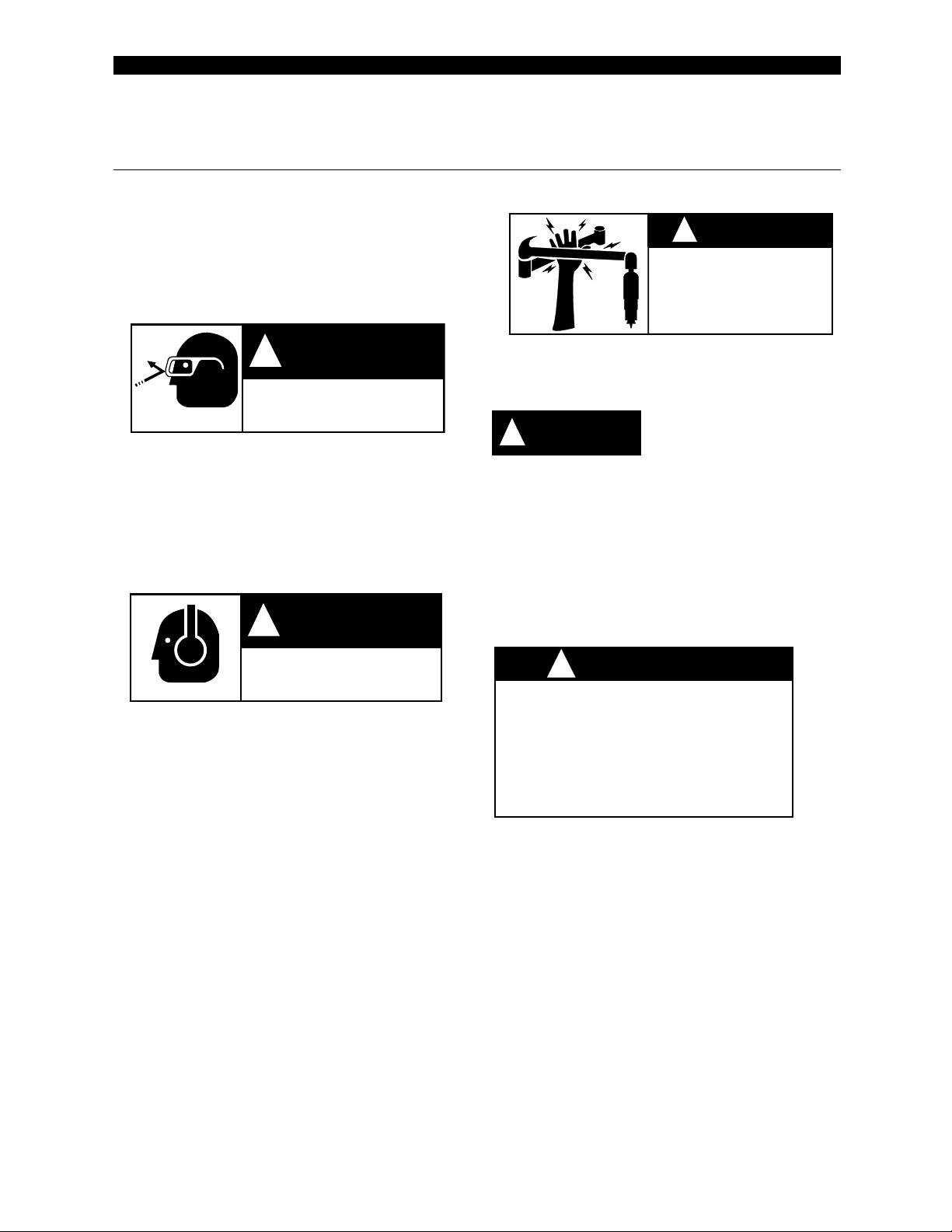
Warning Labels
The warning labels found on these tools are an essential
part of this product. Labels should not be removed. Labels
should be checked periodically for ligibility. Replace warn-
ing labels when missing or when the information can no
longer be read. Replacement labels can be ordered as any
spare part.
Any tool operator should be aware of the following warning
signs and symptoms so that a problem can be addressed
before it becomes a debilitating injury. Any user suffering
prolonged symptoms of tingling, numbness, blanching of
fingers, clumsiness or weakened grip, nocturnal pain in the
hand, or any other disorder of the shoulders, arms, wrists,
or fingers is advised to consult a physician. If it is deter-
mined that the symptoms are job related or aggravated by
movements and postures dictated by the job design, it may
be necessary for the employer to take steps to prevent
further occurrences. These steps might include, but are not
limited to, repositioning the workpiece or redesigning the
workstation, reassigning workers to other jobs, rotating
jobs, changing work pace, and/or changing the type of tool
used so as to minimize stress on the operator. Some tasks
may require more than one type of tool to obtain the
optimum operator/tool/task relationship.
The following suggestions will help reduce or moderate the
effects of repetitive work motions and/or extended vibra-
tion exposure:
• Use a minimum hand grip force consistent with
proper control and safe operation
• Keep body and hands warm and dry (cold
weather is reported to be a major factor contrib-
uting to Raynaud's Syndrome)
• Avoid anything that inhibits blood circulation
—Smoking Tobacco (another contributing
factor)
—Cold Temperatures
—Certain Drugs
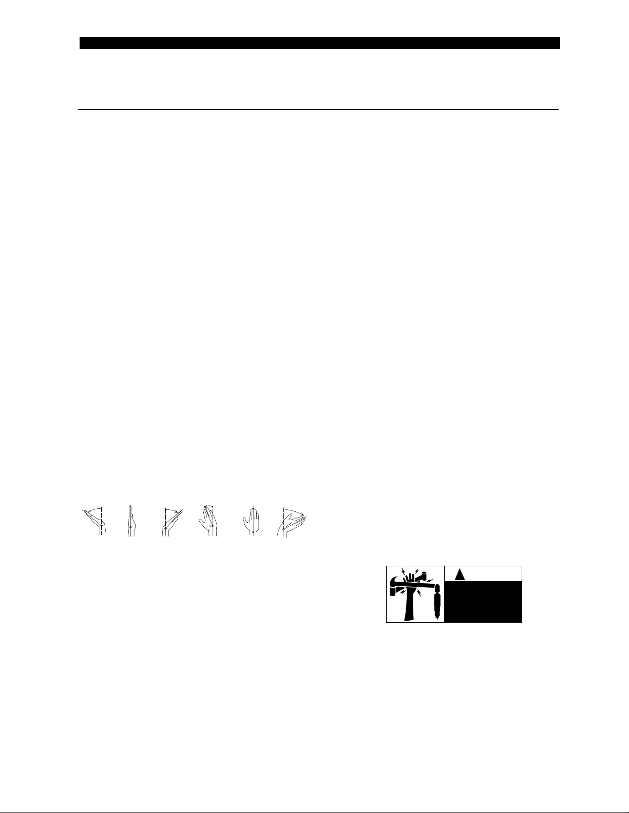
• Tasks should be performed in such a manner
that the wrists are maintained in a neutral posi-
tion, which is not flexed, hyperextended,
or turned side to side.
• Stressful postures should be avoided — select
a tool appropriate for the job and work location
• Avoid highly repetitive movements of hands
and wrists, and continuous vibration exposure
(after each period of operation, exercise to
increase blood circulation)
• Keep tool well maintained and replace worn
parts
Extension Neutral Flexion Radial Deviation Neutral Ulnar Deviation
Avoid Avoid Avoid
OK Avoid OK
CAUTION
!
204036-8
Pinch Hazard.
Keep hands and fingers
away from pinch point.

4
A. Standard Arms 12" or, 18" Model
1. Balance weight of tool
a. Remove extension spring 204033 from arm
spring pin 204006.
b. For heavier tool, move arm spring pin 204006
away from post 204013 to increase spring ten-
sion.
c. For lighter tool, move arm spring pin 204006
toward post 204013 to decrease tension.
2. Adjust height of arm 204026 or 204025
a. Turn rubber spindle 204029 counterclockwise
to increase arm height.
b. Turn rubber spindle 204029 clockwise to de-
crease arm height.
NOTE: Arm should be set as low as possible to mini-
mize up/down travel. IF SPRINGS WILL NOT SUP-
PORT WEIGHT OF ARM, A HEAVY WEIGHT KIT
MAY BE NECESSARY.
ORDER PART NO. 521060-4.
B. Parallel Arm Model 12" or 18"
1. Balance-See A-1.
2. Height-See A-2.
3. Vertical adjustment
a. Loosen both jam nuts 865088 and 204035. Ro-
tate parallel rod 204009 or 204008 to increase
or decrease vertical tool angle.
b. Tighten jam nuts.
C. Adjustable Height Arm
1. Loosen socket head cap screw 845676 and position
column clamp as required. Retighten cap screw.
BALANCE ARMS ADJUSTMENTS
BALANCE ARMS INSTRUCTIONS FOR INSTALLATION
STANDARD ARM
1. Position base 204002 on workbench to allow a 45°
angle between arm 204025 or 204026 and articulat
ing arm 204014 when tool is in proper position to run
fastener.
2. Bolt screwdriver arm base 204002 to workbench.
3. Insert nipple into inlet bushing on tool.
4. Mount tool to arm by inserting nipple into manifold tool
holder 204022 and tighten.
NOTE: If tool torque is to exceed 100 in. lbs.(11Nm),
a longer nipple with two nuts and two lockwashers
should be used. One nut should be tightened against
the manifold tool holder and the other against the tool
inlet bushing. This will prevent the tool from rotating in
the reverse mode.
PARALLEL ARM
1. Position base 204002 on workbench to allow a 45°
angle between boom arm 204014 and articulating arm
204095 or 204096 when tool is in proper position to
run fastener.
2. Bolt screwdriver arm base 204002 to workbench.
3. Attach air hose to tool.
4. Insert tool into parallel tool holder 204015.
5. Adjust height of tool in holder to properly reach work
piece.
6. Equally tighten nuts on tool holder 204087 to secure
tool to arm.
NOTE: Tighten tool holder 204087 securely to pre-
vent tool from rotating in parallel tool holder 204015.
ADJUSTABLE HEIGHT ARM
1. Slide clamp bracket 204017 onto post 204012 and
position at approximate proper height, tighten cap
screw 845676 just enough to keep clamp bracket from
moving.
2. Mount arm assembly onto clamp bracket 204017.
3. See above for standard arm or parallel arm installa-
tion.
4. Adjust final height of clamp bracket 204017 on post
204012 with tool fastened to arm and tighten socket
head cap screw 845676.
NOTE: All numbers refer to drawings. When ordering, use seven-digit part numbers from parts list.

5
A
12 in.
(305 mm)
12 in.
(305 mm)
12 in.
(305 mm)
12 in.
(305 mm)
TORQUE
CAPACITY
10 ft. lbs.
(13.5 Nm)
10 ft. lbs.
(13.5 Nm)
10 ft. lbs.
(13.5 Nm)
10 ft. lbs.
(13.5 Nm)
INSTALLATlON:
NOTE: It is not necessary to disconnect the tool from the Standard Tool Holder to install the swivel tool holder. How-
ever, the air supply should be turned off.
1. Remove manifold pivot pin 204010.
2. Remove manifold tool holder 204022 from the arm.
3. Insert small rectangular block of swivel tool holder (block with threaded hole) into the end of the balance arm.
4. Align threaded hole with pivot pin holes in arm.
5. Insert button head screws through pivot pin holes into threaded hole and tighten.
6. Position manifold tool holder 201690 over large block of swivel tool holder.
7. Align hole in block with pivot pin hole.
8. Reinstall pivot pin.
NOTE: All numbers refer to drawings. When ordering use seven-digit part number from parts list.
SWIVEL TOOL HOLDER FOR BALANCE ARM
204010
SBA WITH STANDARD
TOOL HOLDER
SBA WITH SWIVEL
TOOL HOLDER
SBA SWIVEL
TOOL HOLDER
PART NO. 201601
201690
204010
201690
MOUNTING SURFACE
SINGLE ARM
B
C
A
TOOL WEIGHT
CAPACITY
5 lbs.
(2.3 Kg)
5 lbs.
(2.3 Kg)
5 lbs.
(2.3 Kg)
5 lbs.
(2.3 Kg)
C
18 in.
(457 mm)
18 in.
(457 mm)
18 in.
(457 mm)
18 in.
(457 mm)
SPECIFICATIONS
MODEL NO.
SINGLE ARM
SBA-12
SBA-18
PARALLEL ARM
PBA-12
PBA-18
B
12 in.
(305 mm)
18 in.
(457 mm)
12 in.
(305 mm)
18 in.
(457 mm)

6
201613 SBA-24
201614 SBA-30
201612 SBA-18
201611 SBA-12
204032
201690
204034
INSIDE 204086
204007
812231
OUTSIDE 204089*
204036
204005
204027
833774
881283
204010
204089
812231
204006
204033
204003
202032 202032
SUB ASSEMBLY 201609
NOTE: THRUST WASHERS 863455
MUST BE INSTALLED PROPERLY
AS SHOWN BELOW OR BEARINGS
WILL BE DAMAGED.
*** INCLUDED IN POST
SUB ASSEMBLY 201677
* INCLUDED IN CLEVIS
***204031
***204002
204014 12"
204122 18"
204119 24"
204120 30"
204030
204004
863455
202032
***201609
845688***
202032
863455
204004
BOTH SIDES
LABEL
204029*
204016*
863455
845688*
833109*
863455
204030
204116
PBA-SERIES
SBA-SERIES
204117
204086 (INSIDE)
204089 (OUTSIDE)**
204087**
204088**
833109
204024**
833774**
204011**
204015 Standard**
204167 Extended**
TOOL HOLDER
** 201675 Standard
** 201676 Extended
PBA-18204008
PBA-12
865088
204009
201615 PBA-12
201616 PBA-18
201617 PBA-24
201618 PBA-30
PBA-30
PBA-24
204035 204023
The arms include
the inside bushings
and the warning
labels.
The arms include
the inside bushings
and the warning
labels.

7
PART NO.
201609
201611
201612
201613
201614
201615
201616
201617
201618
201675
201676
201677
201690
202032
204003
204004
204005
204006
204007
204008
204009
204010
204011
204014
204015
204016
204023
204024
204027
204029
204030
204032
204033
204034
204035
204036
204086
204087
204088
204089
204116
204117
204119
204120
204122
204167
812231
833109
833774
845688
863455
865088
881283
CLECO BALANCE ARMS
MODEL PBA & SBA PARTS LIST
Mounts & Accessories are shown on Page 10 thru 13.
QTY.
1
1
1
1
1
1
1
1
1
1
1
1
1
4
1
2
1
1
1
1
1
1
1
1
1
1
1
1
1
1
1
1
2
1
1
2
2
1
1
4
1
1
1
1
1
1
4
1
4
2
4
1
1
DESCRIPTION
Post Subassembly
Arm (17-1/2" Long) SBA-18
Arm (11-1/2" Long) SBA-12
Arm (23-1/2" Long) SBA-24
Arm (29-1/2" Long) SBA-30
Arm (17-1/2" Long) PBA-18
Arm (11-1/2" Long) PBA-12
Arm (23-1/2" Long) PBA-24
Arm (29-1/2" Long) PBA-30
Standard Tool Holder Subassembly
Extended Tool Holder Subassembly
Clevis Subassembly
SBA Tool Holder (Manifold Style) (INCL. 204032, 204034, 204089)
Bearing
Clevis Spring Pin
Pivot Post Pin
Plastic Stop Pin
Arm Spring Pin
Pivot Pin
Parallel Rod (15 -1/2" Long)
Parallel Rod (9 -1/2" Long)
Manifold Pivot Pin
Parallel Pivot Pin
Articulating Arm (12")
Standard Parallel Tool Holder (INCL. 204089)
Spring Arm Clevis (INCL. 204089 & 845688)
Left Rod Clevis
Right Rod Clevis
Plastic Clip
Rubber Spindle
1/2" -13 Nylon Insert Jam Nut
1/4" Close Brass Nipple
Extension Spring
1/4 x 1/4 90° Hose Elbow
Right Rod Clevis Lock Nut
Warning Label
Bushing (Inside) (SBA 1 Only)
Parallel Tool Holder - U Bolt W/Nuts
Parallel Tool Holder - Plastic Clip
Bushing (Outside)
Parallel Rod (21 -1/2" Long)
Parallel Rod (27 -1/2" Long)
Articulating Arm (24")
Articulating Arm (30")
Articulating Arm (18")
Extended Parallel Tool Holder (INCL. 204089)
Retaining Ring
Spindle Nut
Retainer Ring (2 Only for SBA series)
1/4" -20 x 3/8" Lg. Cone Pt. Set Screw
Thrust Washer
Left Rod Clevis Lock Nut
1/4" I.D. Air Hose— 8 feet

8
204034
201690
204032
881283
201611 CSBA-12
201614 CSBA-30
201612 CSBA-18
201613 CSBA-24
204101
204102
OUTSIDE 204089
INSIDE 204086
204007
812231
204027
204036
204005
833774
CSBA-SERIES
204106
844275
204091
204010
204089**
204092
833774
812231
204103
204108
204102*
204101
833774
204030845688*
845688***
201609***
863455
202032
204004
SUB ASSEMBLY 201609
*** INCLUDED IN POST
863455
202032
***204031
***204002
204119 24"
204122 18"
204014 12"
204120 30"
LABEL
BOTH SIDES
202032
863455
204030
204004
863455
202032
833109*
204098*
204104
204105*
204107*
204029*
NOTE: THRUST WASHERS 863455
MUST BE INSTALLED PROPERLY
AS SHOWN BELOW OR BEARINGS
WILL BE DAMAGED.
SUB ASSEMBLY 201695
* INCLUDED IN CLEVIS
SUB ASSEMBLY 201679
* INCLUDED IN CLEVIS
CPBA-24
CPBA-30
204087**
204088**
204086 (INSIDE)
CPBA-SERIES
833109**
204009
204008
204024**
204011**
833774** 865088
204116
204117
CPBA-12
CPBA-18
204023
204035
833774* 201679 ONLY
204011* 201679 ONLY
204098*
TOOL HOLDER
** 201675 Standard
** 201676 Extended
204015 Standard**
204167 Extended**
201616 CPBA-18
201617 CPBA-24
201618 CPBA-30
201615 CPBA-12
The arms include
the inside bushings
and the warning
labels.
The arms include
the inside bushings
and the warning
labels.

9
PART NO.
201609
201611
201612
201613
201614
201615
201616
201617
201618
201675
201676
201679
201690
202032
202150
204000
204001
204002
204004
204005
204007
204008
204009
204010
204011
204012
204013
204014
204017
204018
204019
204020
204021
204023
204024
204027
204029
204030
204031
204032
204034
204035
204036
204086
204087
204088
204089
CLECO BALANCE ARMS
MODEL CPBA & CSBA PARTS LIST& MOUNTS & ACCESSORIES PARTS LIST
DESCRIPTION
Post Subassembly
Arm (11-1/2" Long) CSBA-12
Arm (17-1/2" Long) CSBA-18
Arm (23-1/2" Long) CSBA-24
Arm (29-1/2" Long) CSBA-30
Arm (11-1/2" Long) CPBA-12
Arm (17-1/2" Long) CPBA-18
Arm (23-1/2" Long) CPBA-24
Arm (29-1/2" Long) CPBA-30
Standard Tool Holder Subassembly
Extended Tool Holder Subassembly
Clevis Subassembly
CSBA Tool Holder (Manifold Style)
(INCL. 204032, 204034, 204089)
Bearing
Large Thrust Washer
Wall Mount Plate
Pivot Bracket
Base
Pivot Post
Plastic Stop Pin
Pivot Pin
Parallel Rod (15 -1/2" Long)
Parallel Rod (9 -1/2" Long)
Manifold Pivot Pin
Parallel Pivot Pin
Adjustable Post 30"
Post
Articulating Arm (12")
Post Clamp Bracket
Clamp Plate
Insert Block
External Swivel
Swivel Pin
Left Rod Clevis
Right Rod Clevis
Plastic Clip
Rubber Spindle
1/2" -13 Nylon Insert Jam Nut
1/4" x 2" Lg. Roll Pin
1/4" Close Brass Nipple
1/4 x 1/4 90° Hose Elbow
Right Rod Clevis Lock Nut
Warning Label
Bushing (Inside) (CSBA 1 Only)
Parallel Tool Holder - U Bolt W/Nuts
Parallel Tool Holder - Plastic Clip
Bushing (Outside)
QTY.
1
1
1
1
1
1
1
1
1
1
1
1
1
4
1
1
1
1
2
1
1
1
1
1
1
1
1
1
1
1
1
1
1
1
1
1
1
2
1
1
1
1
2
2
1
1
4
PART NO. DESCRIPTION QTY.
204091
204092
204093
204098
204099
204100
204101
204102
204103
204104
204105
204106
204107
204108
204111
204116
204117
204119
204120
204122
204123
204124
204125
204126
412985
622384
622861
624948
812004
812231
812726
832638
833109
833774
842550
843761
845549
845676
845688
847949
863455
865088
881283
Cylinder
Cylinder Bracket
Regulator
Parallel Cylinder Arm Clevis
(INCL. 204089)
Regulator Bracket
Large Regulator Adaptor
Cylinder Pin
Cylinder Pin Bushing
Spacer
Hose
Hose Connector
Cylinder Elbow
Hose Connector Screw
Muffler
Regulator Label
Parallel Rod (21 -1/2" Long)
Parallel Rod (27 -1/2" Long)
Articulating Arm (24")
Articulating Arm (30")
Articulating Arm (18")
Housing SBT
Shaft SBT
Small Ring SBT Holder
Large Ring SBT Holder
Pin
1/4" -20 x 3/4" Lg. Socket Head Cap Screw
Washer
Small Regulator Adaptor
Button Head Screw
Retaining Ring
Set Screw SBT
Roll Pin
Spindle Nut
Retainer Ring (CPBA requires 10)
Regulator Mounting Bracket Bolt
3/8" -16 Nut
Pipe Nipple
3/8" -16 x 1" Lg. Socket Hd. Cap Screw
1/4" -20 x 3/8" Lg. Cone Pt. Set Screw
Bearing SBT
Thrust Washer
Left Rod Clevis Lock Nut
1/4" I.D. Air Hose— 8 feet
2
2
1
1
1
1
2
2
2
1
1
2
1
2
1
1
1
1
1
1
1
1
1
1
1
4
1
1
2
4
2
1
1
6
1
2
1
2
2
2
4
1
1
Mounts & Accessories are shown on
Page 10 thru 13.

10
MOUNTS & ACCESSORIES FOR BALANCE ARM
Mounts & Accessories parts list shown on Page 9.
.171
.171
204030
LARGE 201608
SMALL 201607
TOOL HOLDER
812726
204126 LARGE 1-35/64" DIA.
204125 SMALL 1-17/64" DIA.
204124
202150
847949
204123
863455
847949
845688
204017
204004
QTY.PART NO. NAME
2
1
1
CLEVIS PIN
SPRING
ARM PIN
204033
204110
204109
204021
204019
HEAVY DUTY WEIGHT KIT
201601 - SWIVEL ASSEMBLY
REGULATOR
521060 - HEAVY DUTY WEIGHT KIT
521060
204020
201601
521013 - AH-30 ASSEMBLY KIT
204002
204031
845688
204004
204017
863455
204030
832638
812004
412985
ADJUSTABLE HEIGHT
201602 - CLAMP BRACKET KIT
622861
863455
843761
204030
845676
204018
843761
622861
204012
845676
204018
204000
622384
845688
201600 - WALL MOUNTSWIVEL TOOL HOLDER
204001
863455
204030
845549
842550
204099
204100 624948
204106
204111
INCLUDED IN SUB-ASS'Y 201610

11

12

13

14
ELECTRIC SCREWDRIVER HOLDER FOR PARALLEL ARM BALANCE ARMS - 301098
ELECTRIC SCREWDRIVER HOLDER FOR SINGLE ARM BALANCE ARMS - 301083

15
Template for Wall & Post Mount
Wall
Post Mount

16
CooperTools
670 Industrial Drive
Lexington, SC 29072
Phone: (803) 359-1200
Fax: (803) 359-2013
www.clecotools.com
This manual suits for next models
3
Table of contents
Popular Industrial Equipment manuals by other brands

Alpha Technologies
Alpha Technologies ALPHA OUTBACK ENERGY Cordex HP LPS04 Installation & operation manual

Abe
Abe CraftCan 15 user guide

Allen-Bradley
Allen-Bradley 140G-G quick start guide

WIKA
WIKA TW61 operating instructions

Siemens
Siemens SIMATIC Compact FF Link operating instructions

R&M
R&M SCM 4 installation guide