RSP TPS400 User manual

Tool parking system TPS400
Product Manual
M8307-1
Tool changers | Swivels | Swivel tool changers | Grippers | Hose packages | Valve units | Tool systems

2 M8307-1 version 2.4

M8307-1 version 2.4 3
The information in this document is subject to change without prior notice and should not be
regarded as an undertaking from Robot System Products AB. Robot System Products AB
assumes no responsibility for errors that may occur in this document.
Robot System Products AB bears no responsibility for damage that is incurred by the use of this
document, or the software or hardware described in this document.
The document, or parts of it, may not be reproduced or copied without prior permission from
Robot System Products AB. It may neither be imparted to a third party, nor otherwise be used
without authorization. Infringement hereof will be subject to action in accordance with the
applicable laws.
Further copies of this document can be obtained from Robot System Products AB at
current prices.
© Robot System Products AB
Robot Systems Products AB
Isolatorvägen 4
SE-721 37 Västerås
Sweden

4 M8307-1 version 2.4
CONTENTS
1 INTRODUCTION .........................................................................................................6
1.1 Safety ..............................................................................................................................7
1.1.1 General................................................................................................................................7
1.1.2 Explanation of warnings......................................................................................................7
2 TECHNICAL SPECIFICATIONS ................................................................................8
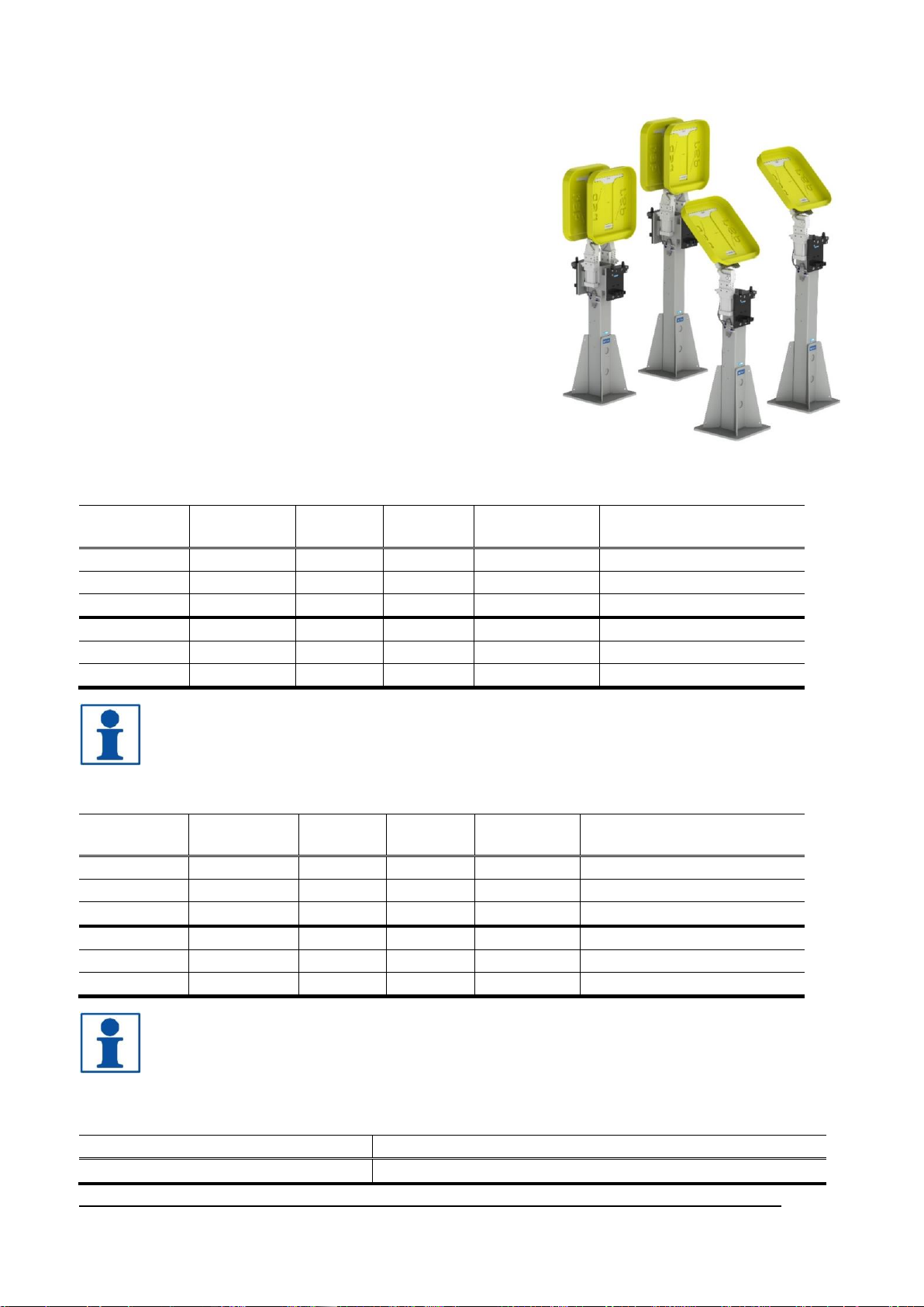
2.1 Tool parking system overview ........................................................................................8
2.1.1 Complementary products....................................................................................................8
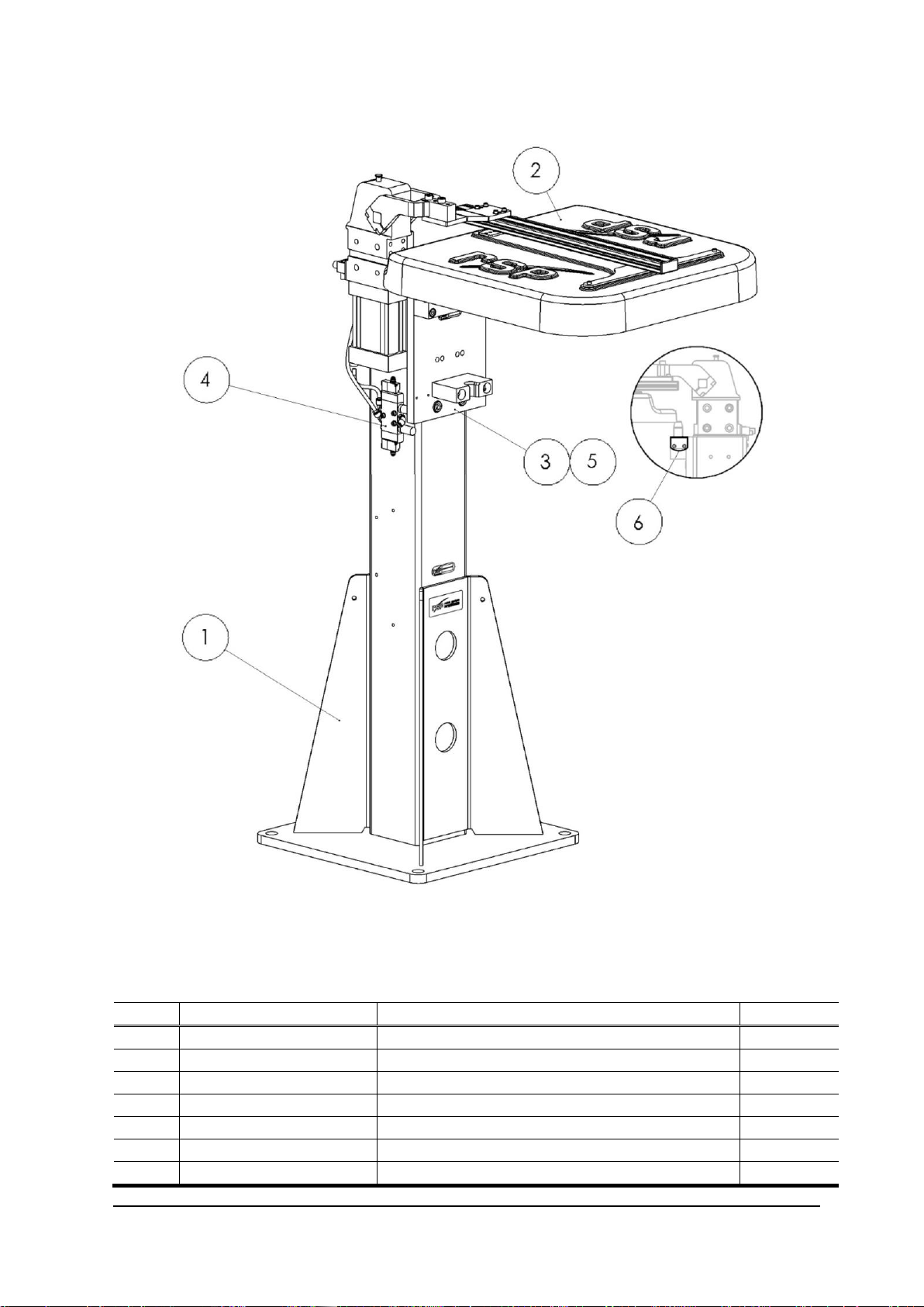
2.2 Tool parking system single, TPS400-1. Articles: P8365 and P8385 .............................9
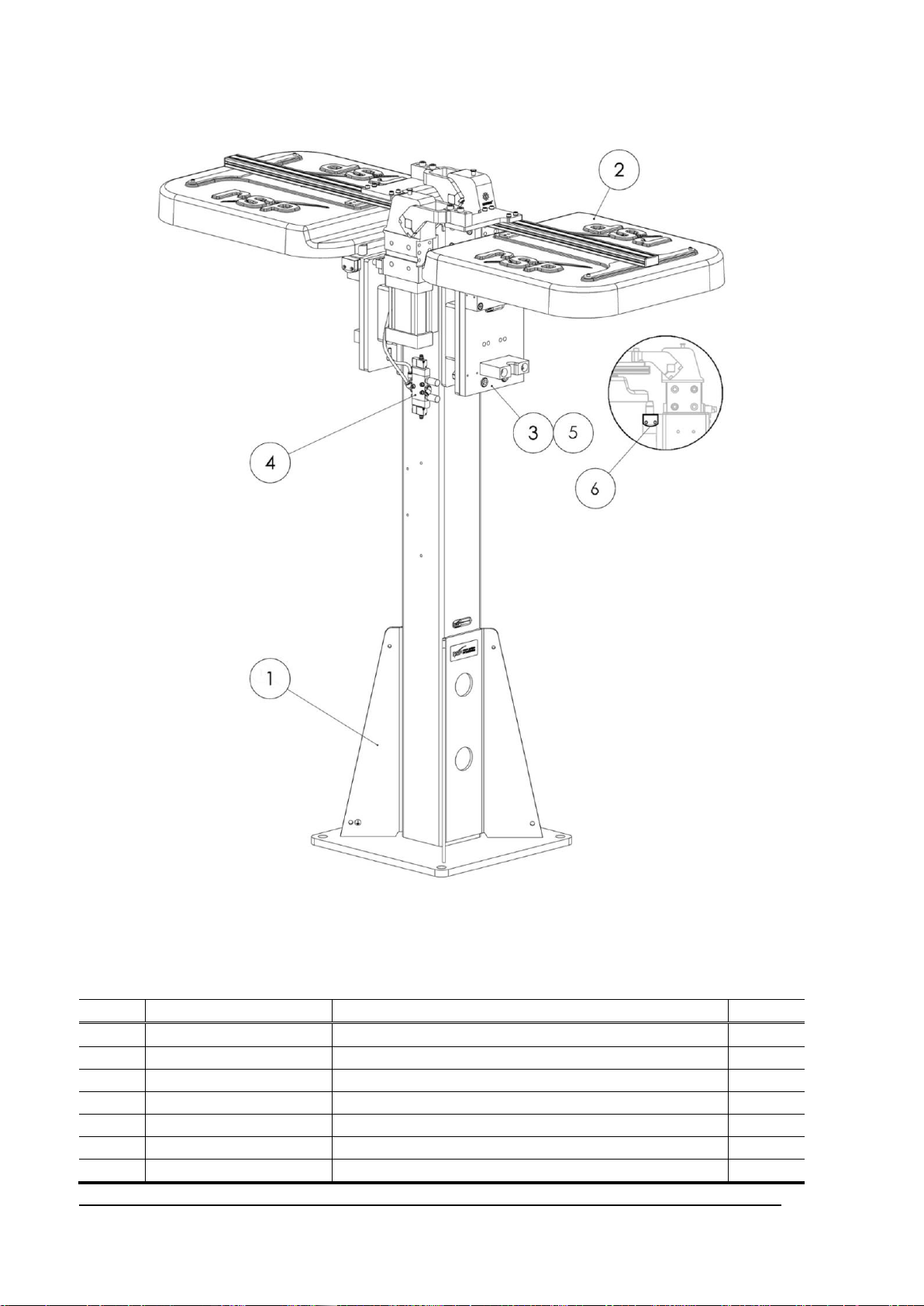
2.3 Tool parking system double, TPS400-2. Articles: P8366 och P8386......................... 10
2.4 Tool parking system single, TPS400-1. Article: P8383............................................... 11
2.5 Tool parking system single, TPS400-2. Article: P8384............................................... 12
3 TOOL PARKING SYSTEM COMPONENTS............................................................13
3.1 Tool stand columns. Article: P8380............................................................................. 13
3.2 Dust covers with pneumatic tilting clamp..................................................................... 14
3.2.1 Dust cover with pneumatic tilting clamp, large. Articles: P8327/P8377............................15
3.2.2 Dust cover with pneumatic tilting clamp, small. Article: P8379.........................................15
3.3 Valve unit for dust cover. Article: P8308A................................................................... 16
3.3.1 Circuit diagram E0186-056 ...............................................................................................17
3.4 Tool hanger. Article: P8302 ......................................................................................... 18
3.5 Load diagram for tool parking system ......................................................................... 19
4 OPTIONS...................................................................................................................20
4.1 Tool plate. Article: P8303A .......................................................................................... 20
4.2 Extension for tool hanger kit. Article: P8371 / P8381.................................................. 21
4.3 Spacer between tool attachment and tool plate. Article: P0186-049.......................... 22
4.4 Tool present sensor, inductive. Article: P8312............................................................ 22
4.5 Tool in stand sensor, passive side. Article: P8369...................................................... 23
4.6 Tool in stand sensor, assembly. Article: P8364 .......................................................... 23
4.7 Spacer for tool in stand sensor. Article: P8373........................................................... 24
4.8 Pedestal for tool stand column. Article: P8376............................................................ 24
4.9 Connection module. Article: P8372 ............................................................................. 25
4.10 Connection module. Article: P8378 ........................................................................... 25
4.11 Connection module. Article: P8372-2........................................................................ 26
4.12 Connection module. Article: P8378-2........................................................................ 27
4.13 Circuit diagram E0186-075 for P8382....................................................................... 28
4.14 Circuit diagram E0186-040 for P8312....................................................................... 29
4.15 Circuit diagram E0186-062-1 for P8372.................................................................... 30
4.16 Circuit diagram E0186-062-2 for P8372-2................................................................. 31
4.17 Circuit diagram E0186-072-1 for P8378.................................................................... 32
4.18 Circuit diagram E0186-072-2 for P8378-2................................................................. 33

M8307-1 version 2.4 5
5 INSTALLATION........................................................................................................ 34
5.1 Tightening torques........................................................................................................34
5.2 Recommended tools for installation.............................................................................34
5.3 Installation of tool hanger on the tool stand column ....................................................35
5.4 Mounting of tool in stand sensor with spacer...............................................................36
5.5 Mounting of tool present sensor...................................................................................37
5.6 Mounting of tool plate on tool attachment....................................................................38
5.7 Mounting of tool hanger extension...............................................................................39
5.8 Installation of dust cover with pneumatic tilting clamp.................................................40
5.9 Installation of connection module.................................................................................43
5.10 Hints............................................................................................................................44
5.10.1 Changing tilting angle .....................................................................................................44
5.10.2 Safety..............................................................................................................................44
5.10.3 Use of tool-in-stand sensor.............................................................................................44
6 MAINTENANCE AND SERVICE ............................................................................. 45
6.1 Tools and required products.........................................................................................45
6.1.1 Recommended tools for maintenance..............................................................................45
6.1.2 Required products.............................................................................................................45
6.2 Wear parts ....................................................................................................................46
6.3 Inspection and cleaning................................................................................................46
6.3.1 Visual inspection (monthly)...............................................................................................46
6.3.2 Cleaning (every third month).............................................................................................46
6.4 Replacement of wear parts...........................................................................................47
6.4.1 Replacement of tool hanger guide pins............................................................................47
6.4.2 Replacement of tool hanger guide block ..........................................................................48
6.4.3 Replacement of tool plate bushings..................................................................................49
6.4.4 Replacement of tool plate guide pin .................................................................................51
6.4.5 Replacement of tool hanger..............................................................................................52
7 SPARE PARTS......................................................................................................... 53
7.1 Dust cover with pneumatic tilting clamp, P8327 and P8377........................................53
7.2 Dust cover with pneumatic tilting clamp, P8379 ..........................................................55
7.3 Tool hangers P8302, including mounting kit and sensor.............................................56
7.4 Valve unit for dust cover P8308A.................................................................................57
7.5 Tool plates P8303A and P8303-1 ................................................................................57
8 DISPOSAL AND RECYCLING ................................................................................ 58
This manual suits for next models
1
Table of contents
Other RSP Industrial Equipment manuals