ABB saco 64D4 User manual

SACO 64D4
Annunciator unit
User´s manual and Technical description
FAULT
ON PROGRAM
1234
5678
9 101112
13 14 15 16
TEST
RESET
ACK
SILENCE
FAULT
ON PROGRAM
1234
5678
9 101112
13 14 15 16
FAULT
ON PROGRAM
1234
5678
9 101112
13 14 15 16
FAULT
ON PROGRAM
1234
5678
9 101112
13 14 15 16
SACO 16D2 SACO 16D2 SACO 16D2 SACO 16D2

2
1MRS 752014-MUM EN
Issued 2000-11-22
Version A (replaces 34 SACO 64 1 EN1)
Checked
Approved
Data subject to change without notice
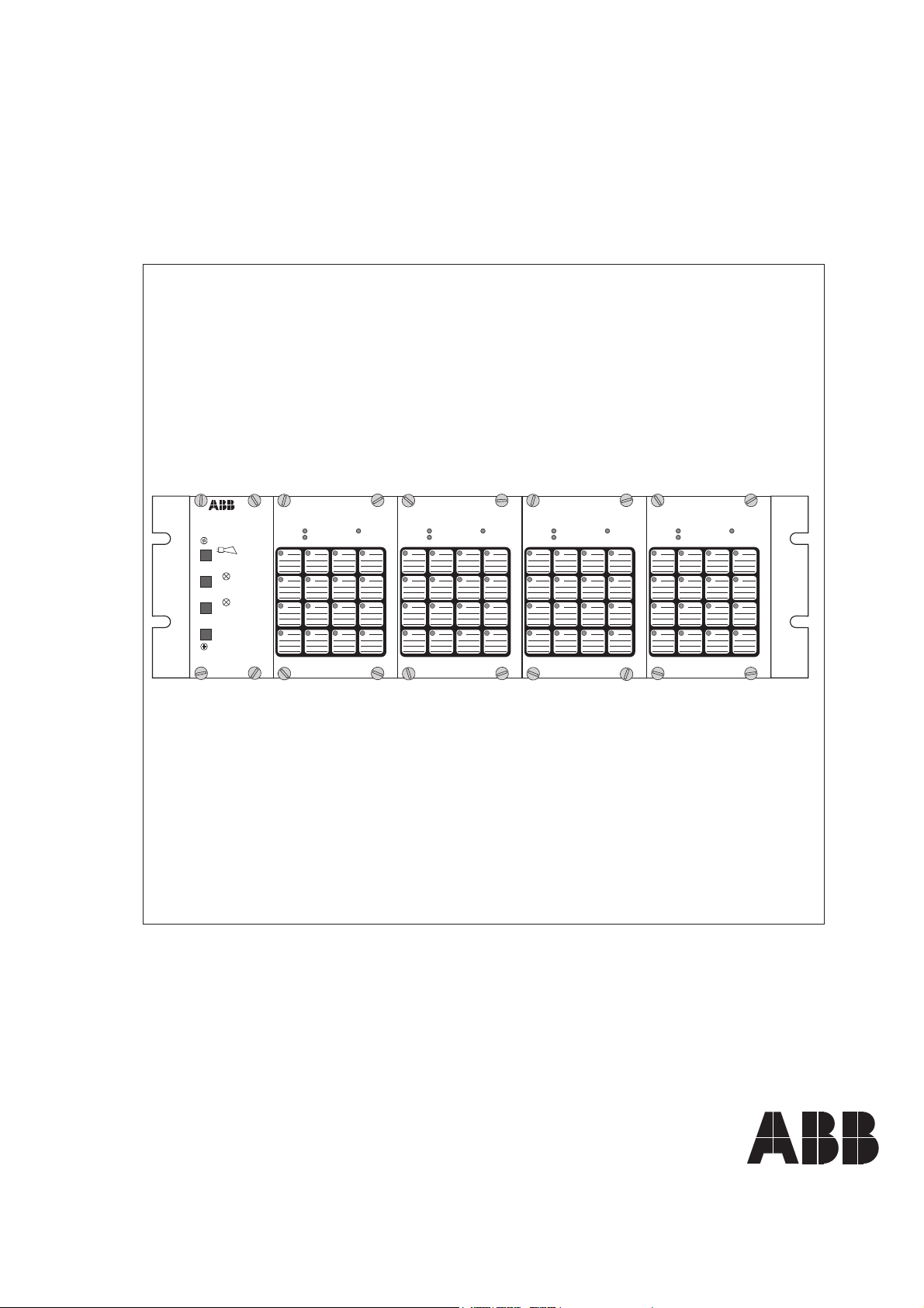
SACO 64D4
Annunciator unit
Table of contents Features .......................................................................................................................... 3
General ........................................................................................................................... 3
Areas of appIication ........................................................................................................ 3
Ilustration of function .................................................................................................... 4
General system data ................................................................................................... 4
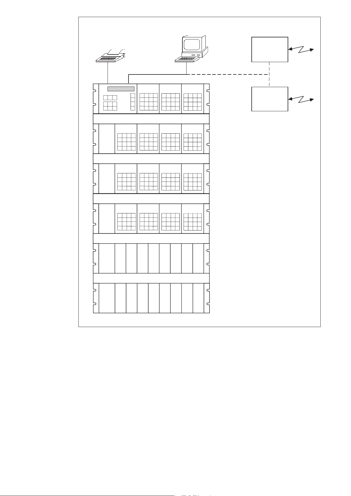
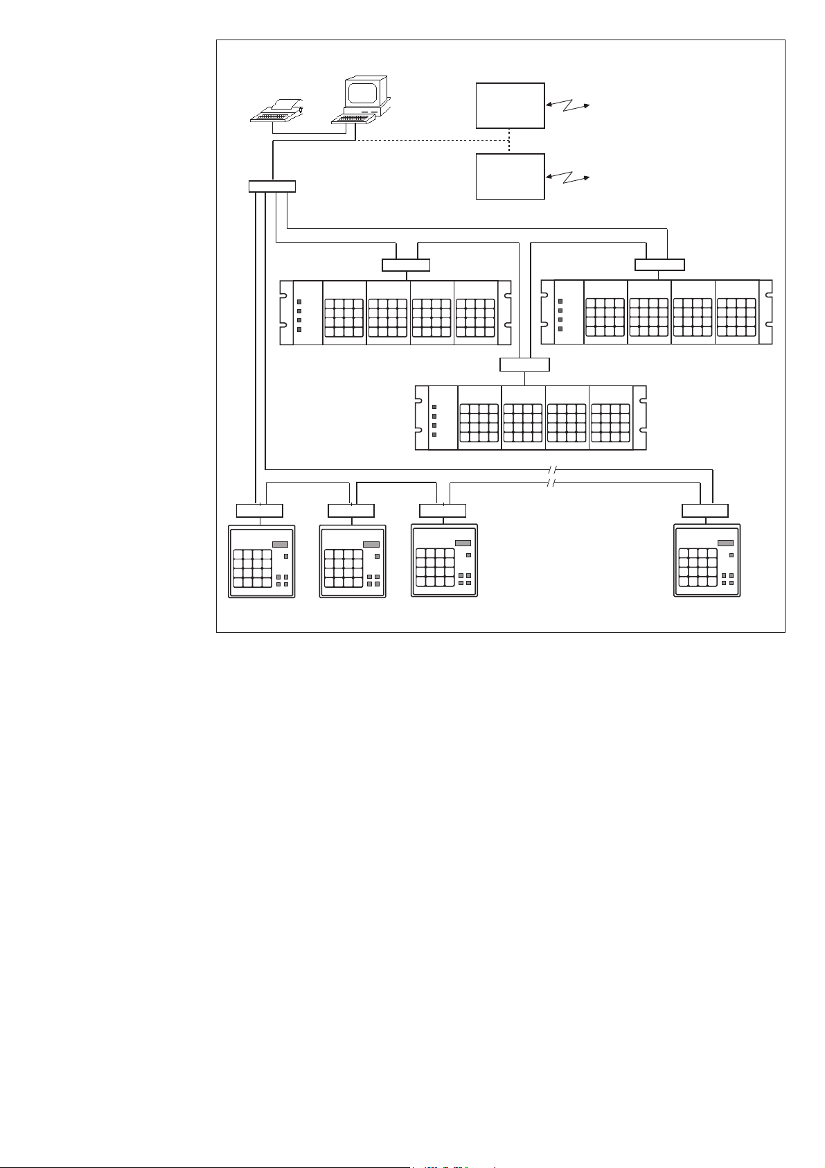
Example of system arrangement ................................................................................ 6
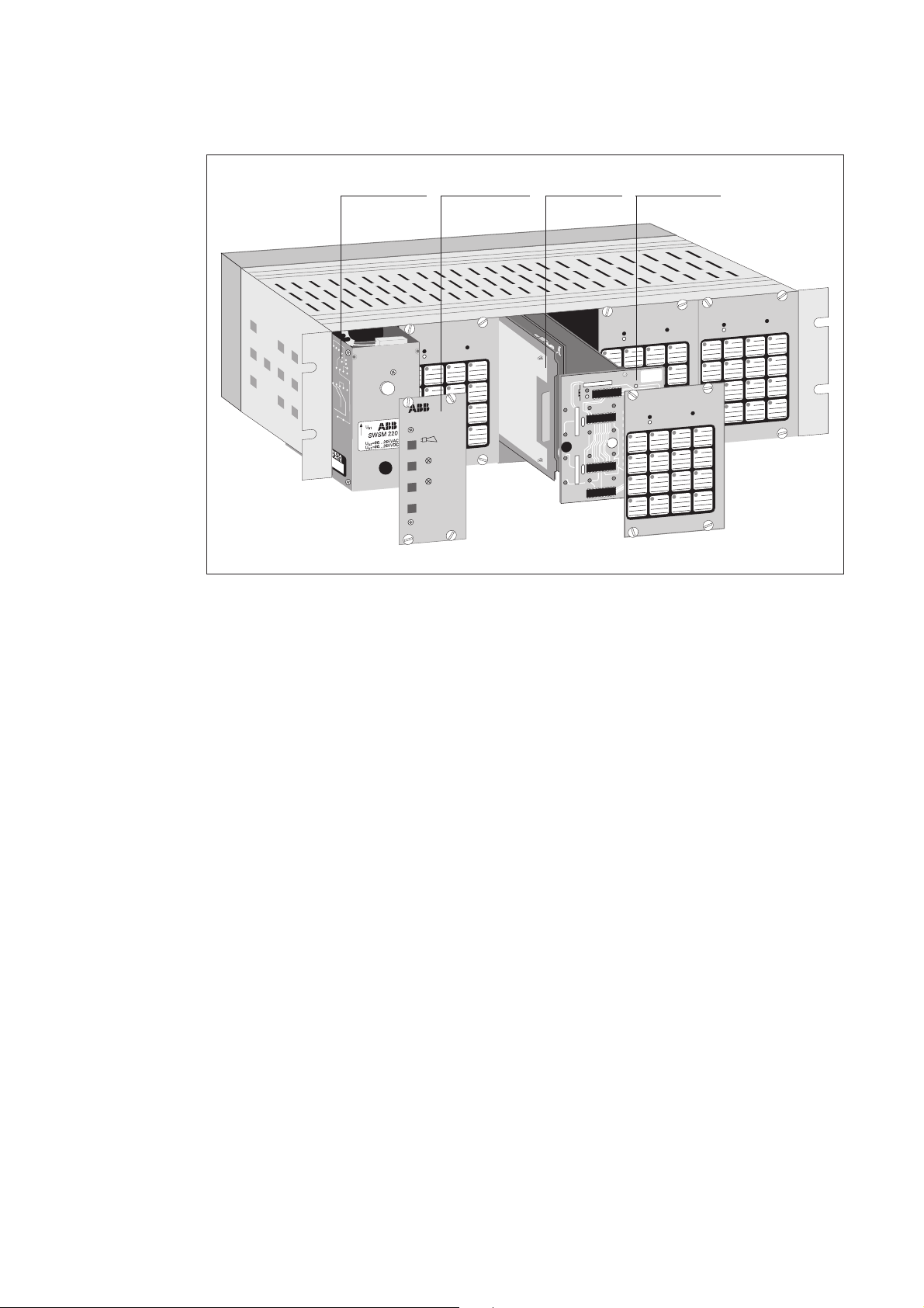
Mechanical design ..................................................................................................... 8
Function of the annunciator module .................................................................... 9
Field contact circuits .......................................................................................... 10
Alarm channel functions .................................................................................... 10
Visual alarm indication....................................................................................... 12
Standardized operational sequences .................................................................... 12
Event register for the serial communication ........................................................ 14
Auxiliary outputs ................................................................................................ 15
Group alarm reflash signals................................................................................. 15
Field contact follower output.............................................................................. 16
Lamp follower output......................................................................................... 17
Audible device output ........................................................................................ 17
Interlockings ...................................................................................................... 18
Example of channel interlocking configuration .................................................. 19
Serial communication interface ............................................................................... 20
Synchronizing of the blinking sequence ............................................................. 20
Parameterization ...................................................................................................... 21
Auxiliary power supply system ................................................................................. 21
Self-supervision output ............................................................................................ 22
Application .............................................................................................................. 23
Mounting ........................................................................................................... 23
Connection diagram ........................................................................................... 24
Terminals and wiring .......................................................................................... 25
Mounting and connection of acknowledge module SWDM 3A1 ....................... 26
Connection to a distributed system with or without event sequence reporting ... 27
Connection to a distributed system .................................................................... 27
Connection of a relay output extension unit type SACO 128R4........................ 28
Start-up .............................................................................................................. 28
Operational test .................................................................................................. 28
Legend plate ....................................................................................................... 29
Programming ................................................................................................................ 30
Signalling and reporting functions ........................................................................... 30
Parameter selection key............................................................................................ 32
Parameter chart........................................................................................................ 32
Channel interlocking scheme................................................................................... 33
Remote information to and from the alarm annunciator ......................................... 34
Event codes.............................................................................................................. 38
Technical data ............................................................................................................... 38
Testing .......................................................................................................................... 40
Maintenance and repair ................................................................................................ 40
Spareparts ..................................................................................................................... 41
Order information ........................................................................................................ 42
Troubleshooting ............................................................................................................ 42

3
Complete annunciator unit with 64 channels
for operation from NO or NC field contacts
Fibre-optic or electric data bus between the
alarm units
Resolution better than 10 ms in the event re-
cording
Independently operating alarm modules
Features Each module provided with a sophisticated
self-supervision system
16 relay reflashes to be freely grouped
Easy programming via SMS Software or a sepa-
rate programming module SACO 16PM
Sophisticated built-in self-supervision system for
encreased reliability
General The annunciator unit type SACO 64D4 is part
of the SPACOM system, an integrated second-
ary equipment system for distribution networks.
The annunciator unit SACO 64D4 is an inde-
pendently operating unit which includes four
16-channel annunciator modules and a power
supply module. SACO 64D4 can be used as a
stand-alone unit or combined with other SACO
64D4 subracks, as a pure signalling system.
Further more it can be integrated into an event
sequence reporting and signalling system. In
such a case the units communicate with each
other over a serial interface and the so called
SPA-bus (or LON-bus), allowing a geographi-
cally distributed configuration of the units.
Serial communication contact with a station
level computer or other higher-level equipment
is also possible. In such a case SACO 64D4 can
be used for data acquisition and even for con-
trol purposes.
Areas of
appIication
The SPACOM components have been devel-
oped and manufactured to meet the most de-
manding requirements as to reliability in op-
eration and immunity to interference.
Another significant feature is the system flexibil-
ity which allows a wide area of applications, e.g.
- electric power plants and substations
- industrial plants and processes
- marine and offshore installations
- technical installations in buildings
- water treatment plats etc

4
Ilustration of
function
General system data
The annunciator unit SACO 64 D4 is com-
posed of four 16-channel alarm modules type
SACO 16 D2B and a doubled power supply
module. The unit is housed in a 19 inch rack
with the height 3 U.
Apart from the 64 channels the unit contains
inputs for resetting of audible device, acknow-
ledgement of alarms, resetting of annunciator
channels and for testing. When using the unit
as a stand-alone annunciator system, an ac-
knowledgement module type SWDM 3A1 can
be connected to these inputs.
Alternatively, the channels 63 and 64 can be
used as inputs for LOCAL/REMOTE func-
tions.
The unit includes 16 output relays for freely
programmable group realarms, so called reflash
alarms. The output relays 15 and 16 can be used
for internal self-supervision and for audible
alarm.
Input signal follower, signal indicator follower
or group alarm follower outputs for every chan-
nel are obtainable from the flat cable connector
included in the unit. These outputs can be uti-
lized by means of the relay unit SACO 128R4
which can hold up to eight 16-channel output
auxiliary relay cards.
The serial interface connection to the SPA-bus
(or LON-bus) is made either by means of a flat
cable connector between subracks or fiber op-
tic connection modules connected to the screw
terminals. The former alternative is used for
uniting units built together.
16
A
16
B
SACO 16D2
C16
A
16
B
SACO 16D2
C16
A
16
B
SACO 16D2
C16
A
16
B
SACO 16D2
C
16
SACO 64D4
Field contact
supply, 48 V DC
Channel inputs 1…16
Remote silence and
acknowledge inputs
Channel inputs 17…32
Remote channel reset
and test inputs
Channel inputs 33…48 Channel inputs 49…64
(Local/remote inputs)
Group alarm
outputs, 1…4 Group alarm
outputs, 5…8 Group alarm
outputs, 9…12
Group alarm
outputs, 1…4
Audible output
Self-supervision output
Internal
supply
SPA-bus, supervising bus and blocking bus
A = Field contact follower output
B = Lamp follower output
C = Group alarm reflash output
SPA-bus
connection
Supply 2:
80…265 V
AC or DC
Supply 1:
19…70 V DC or
80…256 V DC
Fig 1. Block diagram for the annunciator unit SACO 64D4.

5
The same flat cable further contains a monitor-
ing bus for internal faults and an interlocking
bus for the transmission of interlocking signals
between the annunciator modules. When seve-
ral annunciator units SACO 64D4 are built
together, the SPA-bus can be used for synchro-
nizing the flashing sequence of the alarm indi-
cators of the modules.
In a distributed system bus connection mod-
ules type SPA-ZC_ are used for connecting the
annunciator unit to the SPA-bus. Bus connec-
tion modules are available for both optical and
electrical data transmission. The transmission
distances vary with the transmission media, the
following values can be given:
- plastic-fibre: at least 30 m
- glass-fibre: at least 1 km
- pairs of twisted conductor without galvanic
isolation: at least 30 m
- pairs of twisted conductor with galvanic iso-
lation: at least 200 m
Fiber optic media is always recommended due
to its good resistance to electromagnetical in-
terference.
The setting values, groupings and interlockings
of the annunciator modules are stored in non-
volatile memories.
In a stand-alone annunciator system without a
higher level system connected the modules can
be programmed by temporarily connecting the
programming module SACO 16PM to the an-
nunciator modules SACO 16D2B.
If SACO 64D4 is connected to a higher level
system, e.g MicroSCADA the programming
might be made from there. A SMS software can
also be used for programming the SACO 64D4.

6
Example of system
arrangement
Fig 2. Centralized 240 channel annunciator system with field contact doubling outputs.
The maximum size of the alarm system is 35
annunciator modules with 16 channels each, i.e.
a total of 560 channels.
By means of the SACO 148D4 or another highet
level system and a local printer event reports with
time markings can be listed and/or the informa-
tion can be forwarded to other systems.
Without the relay unit SACO 128R4 the annun-
ciator system comprises 16 builtin, freely group-
able reflash relays per subrack. By using the relay
unit with max. 128 relays the necessary number
of contact multiplyings, parallel lamp outputs and
group reflashes is provided for. Further, each out-
put allows grouping of signals.
RS 232
SACO 148D4
SACO 64D4
SACO 64D4
SACO 128R4
SACO 128R4
SACO 64D4
RS232/20 mA
current loop
Printer
PC
MODEM
REMOTE
CONTROL
SYSTEM

7
Fig 3. Distributed annunciator system with event sequence reporting.
The maximum size of the annunciator system
is 35 modules with 16 channels each, i.e. a total
of 560 channels.
By means of the SACO 148D4 or another
highet level system and a local printer event re-
ports with time marking can be listed and/or
forwarded to otehr systems.
The annunciator modules can be connected to
the control data communicator by means of
fibre-optic loops. The individual units are
self-contained and provided with outputs in the
same way as a centralized system. The reflash
grouping for the entire system is made on out-
put contact level.
MicroSCADA
SPA-ZC 21
SPA-ZC 21
SPA-ZC 21
SPA-ZC 22
SPA-ZC 21 SPA-ZC 21 SPA-ZC 21
SPA-ZC 21
SACO 64D4
SACO 64D4 SACO 64D4
SACO 16D1 SACO 16D1 SACO 16D1
120
SACO 16D1
23
RS232/20 mA
current loop
Printer REMOTE
CONTROL
SYSTEM
MODEM
Fiber optical loop

8
Mechanical design The annunciator unit is composed of the fol-
lowing Euro-size withdrawable modules (100 x
160 mm):
- a power supply module SWSM 220A48 or
SWSM 220A220
- four microprocessor modules SWPM 1A1B
- four input/output modules SWIM 2A1B
FAULT
ON PROGRAM
1234
5678
9 101112
13 14 15 16
FAULT
ON PROGRAM
1234
5678
9 101112
13 14 15 16
FAULT
ON PROGRAM
1234
5678
9 101112
13 14 15 16
TEST
RESET
ACK
SILENCE
FAULT
ON PROGRAM
234
678
10 11 12
14 15 16
1
5
9
13
SACO 16D2
SACO 16D2
SACO 16D2 SACO 16D2
SWPM 1A1SWIM 2A1SWSM 220- SWDM 3A1
Fig 4. Mechanical design of SACO 64D4.
The modules are interconnected on the mother
PC-board. The mother PC-board also contains
the card connectors for the plug-in modules and
the wiring for the inputs and outputs.
The rack housing the modules is a 19 inch, so
called Euro-rack with a height of 3 U (about
133 mm).
When mounting several SACO 64D4 subracks
together or combining them with other
SPACOM subracks, a space of 1 U, i.e. about
44 mm, should be left between the subracks.
The subrack is suitable for mounting in a 19
inch frame or it may be flushmounted. At flush
mounting the depth behind the mounting sur-
face can be reduced by 40 mm by using a rais-
ing frame, type SRH-ZX1.
The subrack is made of anodized aluminium.
The rear panel and the ventilation grids are made
of galvanized sheet steel. The front panels are of
aluminium and covered by a plastic membrane.
At panel mounting the degree of protection by
enclosure will be IP 40.

9
Fig 5. Rear view of SACO 64D4.
The rear part of the subrack holds the screw
terminal blocks for the incoming and outgoing
circuits. Each screw terminal is dimensioned for
one or two multistrand conductors of max. 2.5
mm2. In order to avoid too thick bunches con-
ductors of 0.75 mm2are recommended.
The hinges of the rear part allow maintenance
measures to be taken without loosening any
wires.
SACO 64D4 is connected to the SPA-bus by
means of SPA-ZC series connection modules.
Fig 6. Connection module SPA-ZC 21 mounted on the SACO 64D4.
Function of the
annunciator modules
SACO 16D2B is a versatile and flexible annun-
ciator module with 16 channels. Its main func-
tion is to supply the user with information about
changes in the signal contact states in the proc-
ess to be supervised. The module is also used
for fault signal and event sequence recording, a
function which allows the origin and develop-
ment of the fault to be analyzed afterwards.
The basic functions of the module is illustrated
on page 10.
The central unit continuously compare new in-
formation with previously received information.
When a change of state occurs, the channel
starts, and if the duration of the change exceeds
a preset input delay, the event will be recorded.
The reflashes are activated according to a preset
operational scheme. Further, the events are re-
corded in the internal event register.
When a PC (with e.g. SMS software) is included
in the system, the settings are made over the
SPA-bus. Alternatively, the setting can be made
by using a portable programming module type
SACO 16PM. All setting values are stored in
non-volatile EEPROM type memories.
Alternatives for acknowledgement and resetting:
- By means of separate push-buttons via exter-
nal acknowledge inputs
- The push-buttons in the acknowledge mod-
ule SWDM 3A1 via external acknowledge in-
puts.
The acknowledgemodule SWDM 3A1 is, if in-
cluded, located in front of the power supply
module to the left in the rack.
1 13
2 14
3 15
4 16
5 17
6 18
7 19
8 20
9 21
10 22
11 23
12 24
25 37
26 38
27 39
28 40
29 41
30 42
31 43
32 44
33 45
34 46
35 47
36 48
49 61
50 62
51 63
52 64
53 65
54 66
55 67
56 68
57 69
58 70
59 71
60 72
73 85
74 86
75 87
76 88
77 89
78 90
79 91
80 92
81 93
82 94
83 95
84 96
97 109
98 110
99 111
100 112
101 113
102 114
103 115
104 116
105 117
106 118
107 119
108 120
121 133
122 134
123 135
124 136
125 137
126 138
127 139
128 140
129 141
130 142
131 143
132 144
SERIAL NO
Made in Finland
SACO 64D4
RS 811 653-AA 21
U
N
= 80…265 V ~ U
N
= 19…70 V
U
N
= 80…265 V
1 13
2 14
3 15
4 16
5 17
6 18
7 19
8 20
9 21
10 22
11 23
12 24
25 37
26 38
27 39
28 40
29 41
30 42
31 43
32 44
33 45
34 46
35 47
36 48
49 61
50 62
51 63
52 64
53 65
54 66
55 67
56 68
57 69
58 70
59 71
60 72
73 85
74 86
75 87
76 88
77 89
78 90
79 91
80 92
81 93
82 94
83 95
84 96
97 109
98 110
99 111
100 112
101 113
102 114
103 115
104 116
105 117
106 118
107 119
108 120
121 133
122 134
123 135
124 136
125 137
126 138
127 139
128 140
129 141
130 142
131 143
132 144
SERIAL NO
SPA
1 1 0 0
RS485
0 0 1 1
1
S
0
M
SPA-ZC 21
BB
BM MB
MM
RS 951 021-
Tx Rx
15432
-----OPEN-----
Made in Finland
SACO 64D4
RS 811 653-AA 21
U
N
= 80…265 V ~ U
N
= 19…70 V
U
N
= 80…265 V

10
Field contact circuits The electrical contacts of the devices sensing the
process condition must be potential-free while
the annunciator unit itself generates the 48 V dc
field contact voltage. This specification also ap-
plies to the remote control inputs.
The power unit supplying voltage to the field
contacts also provides a full galvanic isolation
between the field contact circuits and the elec-
tronic circuits of the annunciator unit it self as
well as the system earth. The channel inputs are
provided with transient suppression circuits and
input voltage limiters.
The alarm channels can be individually pro-
grammed for operation from normally closed
(NC) or from normally open (NO) contacts.
The annunciator is provided with an integrated
field contact voltage supervision function. When
a fault is detected the LED indicator marked
"FAULT" on the front panel is switched on and
internal supervision output relay operates. The
fault message can also be transmitted over the
serial communication link to the higher system
levels.
TRANSIENT
SUPPRESSION To alarm
channel
48 VDC
From the internal
supply module
0 V
48 V
Field
contact
Galvanic isolation
Fig. 7. Principle of alarm channel input.
Alarm channel
functions
An alarm channel is composed of a number of
functional blocks illustrated below. The lists of
variables underneath some of the blocks indi-
cate that a certain parameter can be selected from
a set of given values, i.e. the parameter can be
programmed. The selected parameter is shown
in the numerical display when called up during
the programming.
Fig. 8. Block schemating diagram for an alarm channel.
SEQUENCE
LOGICS
Reflash B
&Reflash A
Interlocking
output (0) Ack. Reset
1
Alarm indicator
Audible alarm
Reflash A
interlocking
input (1)
Channel
interlocking
input (2/3)
FIELD
CONTACT
SELECTION INPUT DELAY RESET DELAY
48 V
Field
contact
Galvanic isolation
and transient
suppression
0 = NO field contact
1 = NC field contact
2 = NO field contact,
no return function
3 = NC field contact,
no return function
4 = NO and NC field
contact
5 = pulse counter,
counts on closing
function
6 = pulse counter,
counts on opening
function
7 = pulse counter,
counts on both
closing and opening
function
0 = 5 ms
1 = 20 ms
2 = 100 ms
3 = 1 s
4 = 5 s
5 = 20 s
6 = 60 s
7 = 160 s
0 = 5 ms
1 = 20 ms
2 = 100 ms
3 = 1 s
4 = 5 s
5 = 20 s
6 = 60 s
7 = 160 s
-
0 = sequence 0-4
1 = sequence 0-4,
audible alarm
also at dis-
appering alarm
2 = field contact
following
Silence

11
After the galvanic separation and the transient
suppression the incoming field contact signal is
analyzed and identified in respect of signal type.
Seven input signal types are specified:
0 = signal from normally open contact, with
return function
1 = signal from normally closed contact, with
return function
2 = signal from raising edge only
3 = signal from falling edge only
4 = signal from raising and the falling edge
5 = pulse counter, counts by contact closing
6 = pulse counter, counts by contact opening
7 = pulse counter, counts by contact opening
and closing.
Parameter S3
The input signal types 2, 3 and 4 are usually
selected when event recording is used. For ex-
ample the signal indicating that a circuit breaker
has tripped is noticed and registered with its
raising edge only.
The pulse counter is used only when the data is
transferred to a higher level system. The pulse
counter channels sequence logic is to be set to
signal following without blinking and audible
alarm functionality (S4 = 2). The reflash relays
connected to the pulse counter channels are to
be configured as ISR, Impulse Shaping Reflash
(S1 or S2 = 2).
The channels configured as pulse counters counts
pulses up to 3 Hz. The capacity of the counter is
0...29999. The counter is freely presettable within
this range. When the pulse counter reaches 29999
it starts over again from 0.
The counter can be read and set only via the SPA
bus with the channel specific parameter V5. When
the parameter V5 is read the present value of the
pulse counter is received, when written the preset
(start) value for the pulse counter is given.
The counters memory circuit has no battery
backup, hence the stored values are lost if the
auxiliary power drops off and the counter starts
over again from 0 or its preset value when the
auxiliary power returns.
When a change of status has been detected for
an incoming field contact signal and the new sta-
tus exceeds the channel input delay in duration,
the operation sequence memory is activated.
The channel input delay can be selected from a
set of eight alternative values using the program-
ming module SACO 16 PM:
0 = 5 ms
1 = 20 ms
2 = 100 ms
3= 1s
4= 5s
5 = 20 s
6 = 60 s
7 = 160 s
8 = another value, which is programmed via the
serial interface
Via the serial interface the channel input delay
can be freely programmed. Refer to the param-
eter list in the end of this manual.
Parameter S1
If the change-of-status of a field contact signal
means that the signal returns to normal, the
channel reset delay time must be exceeded be-
fore the change is registered. The delay time al-
ternatives are the same as those for the input
delay but the channel reset delay times are se-
lected separately (S2).
When the operation sequence logic circuits are
activated, the visual alarm displays start func-
tioning according to the programmed opera-
tional sequence (flash sequence). The most suit-
able of five standard operational sequences is
chosen by programming. All changes of status
of the incoming signals are stored in the event
register irrespective of the selected operational
sequence for the visual alarm displays.
The sequence memory is acknowledged/reset in
the following order:
SlLENCE = resets the audible alarm
ACKNOWLEDGE = indicates recognition of
an alarm
RESET = returns the channel to
the normal state
The alarm channels each generate two reflash sig-
nals A and B which can be linked to the auxiliary
reflash output relays, for details please refer to
section "Group alarm reflash signals" on page 15.
Each alarm channel is also provided with two
interlocking signal inputs and one interlocking
signal output. The interlocking signal inputs/
outputs are:
0 = interlocking signal output. Can be con-
nected to the other channels
1 = interlocking signal input. Blocks the reflash
signal A
2 = interlocking signal input. Blocks the whole
alarm channel, returns as acknowledged
alarm
3 = interlocking signal input. Blocks the whole
alarm channel, returns as a new alarm.
Parameter S7 and S9
The interlocking signal output is also always ac-
tivated by an interlocking signal input being
activated in the same channel.

12
Visual alarm
indication
The state of the alarm channel is indicated by
super-bright LEDs. A legend plate of transpar-
ent film is inserted in a slot at the edge of the
also transparent plastic overlay. For more infor-
mation, see section "Legend plate", page 29.
Acknowledge and reset is done with a push-but-
ton located on in module SWDM 3A1 located,
if included, to the left in the rack or with two
external push-button. The reset indicator LEDs
on the front panel marked SILENCE, ACK,
RESET/TEST shows which of the actions is to
be performed. The reset sequence depends on
the operational sequences.
FAULT
ON PROGRAM
1234
5678
9 101112
13 14 15 16
TEST
RESET
ACK
SILENCE
FAULT
ON PROGRAM
1234
5678
9 101112
13 14 15 16
FAULT
ON PROGRAM
1234
5678
9 101112
13 14 15 16
FAULT
ON PROGRAM
1234
5678
9 101112
13 14 15 16
SACO 16D2 SACO 16D2 SACO 16D2 SACO 16D2
Channel window with
indicator LED and
legend textPROGRAMON
FAULT
SILENCE
ACKNOWLEDGE
RESET
TEST
Fig. 9. Alarm indicators and push-buttons of the annunciator unit SACO 64D4.
Standardized
operational sequences
The annunciator unit is supplied with five
standardized field-selectable operational sequence
alternatives of which the most adequate one for
a certain application is selected for each annun-
ciator module. The operational sequences are:
0 = ISA A, automatic reset
1 = ISA A-1, automatic reset, separate reset of
audible alarm
2 = ISA M-1, manual reset, separate reset of au-
dible alarm
3 = ISA R-1, manual reset, separate reset of au-
dible alarm, visual ringback on return
4 = DIN 19235, manual reset after return to
normal if acknowledged while alert, visual
ringback on return if acknowledged before
return to normal
Parameter S17
The above operational sequences are common
to all the 16 channels in the module. However
the sequences can be altered on a per-channel
basis according to the following:
0 = indications according to the selected se-
quence
1 = indications according to the selected se-
quence but including audible alarm also on
return. Valid only for sequences ISA R-1 and
DIN 19235
2 = field contact following indication without
audible alarm
Parameter S4
The acknowledge/reset operations required are
determined by the annunciator unit itself. The
annunciator unit is provided with two external
control inputs, one for remote resetting of the
audible device and an other for remote acknowl-
edge/reset of the alarm channels.
NOTE!
There is also a Test pusch-button in the module
SWDM 3A1. The test is accomplished by press-
ing the test button continually for approximately
1 second which causes all LED indicators to
light up. The visual displays can not be tested if
an alarm channel is unacknowledged or not re-
set. Pressing the test button for approximately
15 s activates the self-supervision auxiliary out-
put relay and the FAULT LED.

13
Automatic reset
ISA A
ON
OFF
ON
OFF
ON
OFF
ON
OFF
ON
OFF
ON
OFF
ON
OFF
ON
OFF
ON
OFF
ON
OFF
ON
OFF
ON
OFF
ON
OFF
ON
OFF
ON
OFF
ON
OFF
ON
OFF
ON
OFF
ON
OFF
ON
OFF
ON
OFF
Field contact
Acknowledge
Reset of audible output (Silence
)
Audible output
Field contact
Visual alarm indicator
Acknowledge
Audible output
Field contact
Visual alarm indicator
Acknowledge
Reset of audible output (Silence
)
Audible output
Reset
Field contact
Visual alarm indicator
Acknowledge
Reset of audible output (Silence
)
Audible output
Reset
Field contact
Visual alarm indicator
Acknowledge
Reset of audible output (Silence
)
Audible output
Reset
Automatic reset, separate reset of audible output
ISA A-1
Manual reset, separate reset of audible output
ISA M-1
Manual reset, visual ringback and separate reset of audible output
ISA R-1
Manual reset, visual ringback if acknowledge is done before the alarminput returns
to normal state, separate reset of audible output
DIN 19235
ON
OFF
ON
OFF
ON
OFF
ON
OFF
ON
OFF
ON
OFF
Visual alarm indicator
Fig. 10. Selectable alarm sequences.

14
Event register for the
serial communication
The annunciator unit incorporates an event reg-
ister which contains information on the type of
event and the channel number including a syn-
chronous time stamp. This enables a higher level
system to read out events from the annunciator
over the SPA bus serial communication. The
event register holds 50 events. The time stamps
are relative and the time span is max. 60 s. The
clocks of the interconnected units are synchro-
nized, generally once per second, by the higher
level system (the SPA bus master). The time
resolution between the channels is 5 ms.
The annunciator unit also includes a channel
matrix register which operates in parallel with
the event register and in which each channel
corresponds to one bit. If a channel is activated
during an overflow situation of the even regis-
ter, the corresponding bit in the matrix register
is activated.
Overflow
Overflow
Time Slave Channel Code
2
1
500
Adding of
users text
Event register
Clock
SPA-bus
Synchronization
SRIO
Printer
Host system
Time Slave Channel Code
Channel CodeTime
Events
Clock
0 - 60 s
SACO alarm module
Event
register
Overflow
1234
5678
91011
14 16
Event overflow
matrix register
SPA-bus
Clock
0 - 60 s
Time
1
2
3
.
.
.
.
n
Channel Code
Events
SPA-bus
SPACOM protective relay module
Event
register
12
13 15
Time marking: year, month,
day, hour and minute
1
2
3
.
.
.
.
.
.
.
48
49
50
Fig. 11. Event registration in SPACOM systems.

15
Auxiliary outputs The annunciator includes 16 auxiliary output
relays. 14 output relays act as group alarm reflash
output elements, one auxiliary output relay is
dedicated for control of an audible device and
one relay acts as an auxiliary output element for
the internal self-supervision function. In a cen-
tralized system (i.e. when several SACO 64D4
are connected together) there might be no need
to use the audible sevice output and the
selfsupervision output on every unit separately,
hence all 16 outputs can be used as Group Alarm
Reflash outputs.
By using the relay unit SACO 128R4, which
may accommodate a total of 128 output relays,
and which is connected to the annunciator
modules by means of flat cables, a total of 16
reflash group outputs, 16 contact doubler out-
puts and 16 paralell lamp outputs can be pro-
vided from each annunciator module. These
outputs can also be grouped by means of the
grouping module SACO 64C5
Group alarm reflash
signals
Each alarm channel generates two reflash out-
put signals, A and B, which can be freely linked
to the reflash output relays to form group alarm
reflash functions. The group alarm reflash out-
put relays can be given one of the following
modes of operation selectable by programming,
separately for both of the output relays:
0 = FCFR, Field Contact Following Reflash
1 = AACR, Acknowledge Action Controlled
Reflash
2 = ISR, Impulse Shaping Reflash
3 = FCFR + ISR, Field Contact Following
Reflash with a 300 ms interruption of the
reflash signal any time a new alarm signal
joins in an already active group alarm bunch
4 = FCFR + AACR, Field Contact Following
Reflash and Action Controlled Reflash (se
figure below)
Parameter S1…S16 (Module related settings)
Channel input delays Channel reset delay
Alarm 1
Alarm 2
Acknowledge
Signal following
Alarm memory following
Pulse type
Signal following with break
FCFR + AACR
Fig. 12. Principle diagram for the different reflash signal types. The alarm signals 1 and 2 are
grouped to the same group alarm reflash signal.
NOTE!
The reflash signals are always accompanied by
a certain basic delay. The basic delay time de-
pends on the number of incoming alarm sig-
nals per time unit and on the number of inter-
nal interlocking levels in use. The basic time
delay of the reflash signal is 70 ms if only one
alarm signal is received within a time period of
200 ms and if no interlockings are used.

16
Fig 13. Principle diagram for building up group alarm functions. Output relay 15 and 16 are
available for group reflash only in a multi rack system, for instance in a combination with Saco
128R4 relay rack. When SACO 64D4 is used standalone the output relays are used as internal
fault and audible alarm outputs.
CHANNEL
1
CHANNEL
2
A
B
A
B
S5
S6 1
S5
S6 2
GROUPING
REFLASHMODE
S1
REFLASHMODE
S2
S5
S6
16
CHANNEL
16
A
BREFLASHMODE
S16
0 = VSJ
1 = MSJ
2 = PJ
3 = VSJ + ISR
GROUPALARM 16
GROUPALARM 1
GROUPALARM 2
Field contact follower
output
Each alarm input provides a control signal which
can be used as a field contact follower signal.
The signal which is instantaneous and activated
when the field contact is closed, can be used to
control an auxiliary relay in the relay unit SACO
128R4. Four 16-pole flat cable contacts are avail-
able for this purpose on the mother PC-board
behind the rear panel of the rack.
FLAT CABLE
+ 24 V
SACO 128R4
FIELD CONTACT
FOLLOWER
TO THE ALARM
MODULES
SACO 148D4 OR
SACO 64D4
48 V
FIELD
CONTACT
0V
Fig 14. Principle diagram for a contact follower output.

17
Lamp follower output Each annunciator module includes a 16-pole
flat cable connector marked X2 holding the
lamp follower control signals. By using the re-
lay unit SACO 128R4 a lamp follower contact
output can be obtained from each channel. The
function of the output is identical with that of
the built-in alarme indicator.
FLAT CABLE
+ 24 V
SACO 128R4
LAMP FOLLOWER
8 V
INTERNAL LAMP
LAMP CONTROL
SIGNAL
SACO 148D4 or
SACO 64D4
Fig 15. Principle diagram for a lamp follower output.
Audible device output Generally the relay output for control of an au-
dible device operates if one of the alarm chan-
nels is activated. Every channel can also be sepa-
rately programmed to deliver an audible ring-
back when the alarm channel returns to normal
state. If an alarm channel has been programmed
for a sequence providing a field contact follow-
ing visual indication only, no audible alarm will
be generated, please refer to "Standardized op-
erational sequences" on page 12.
The audible device can be silenced by means of
the silence push-button or by means of an exter-
nal control signal applied to the remote silence
control input (128) of the annunciator unit.
An incoming alarm signal, for which only the
audible alarm has been silenced but the alarm
signal has not been acknowledged nor reset, will
not produce a new audible alarm if the field
contact starts "pumping".
The relay output for controlling of an audible
device is blocked when the annunciator unit is
in remote state. The audible alarm can also be
sent over he serial communication interface.
Channell 1
Channel 2
Channel 3
Channel 16
Audible
alarm
memory
Reset of audible
output
(Silence)
Audible device
relay output
Fig. 16. Principle diagram for the audible alarm.

18
Interlockings It has been mentioned in the section describing
the functions of an alarm channel that each
channel is provided with three interlocking in-
put types, 1, 2 and 3, and one interlocking out-
put type, 0.
The interlocking input type 1 prohibits, when
energized, only the channel reflash signal type
A from being transmitted, while the interlock-
ing input type 2 blocks the whole alarm chan-
nel and if the blocking drops of while the chan-
nel is still active, the channel will be indicated
as an acknowledged alarm. The interlocking
input type 3 also blocks the whole channel but
returns as a new alarm when the interlocking
drops of. The interlocking output type 0 is acti-
vated by an alarm channel being activated or by
one of the interlocking inputs being activated.
The feature mentioned last enables the annun-
ciator unit to be programmed with up to eight
interlocking levels.
Note!
If more than three interlocking levels are used
it will effect the resolution on the time stamp
for the event register.
The interlockings are distributed between the
different channels via eight internal interlock-
ing lines, see figure on page 19. In addition the
first four interlocking lines can be used for trans-
mitting blocking signals between the annuncia-
tor modules.
Each channel can be connected to two inter-
locking lines. This means that alternatively both
the interlocking inputs of an alarm channel are
connected to two different interlocking lines,
or the interlocking output and one of the
interlocking inputs are connected to two dif-
ferent interlocking lines.
When an external interlocking signal is to be
brought into the annunciator unit, one of the
alarm channels can be used as an interlocking
input. In this case the alarm channel may be
given the field contact following visual indica-
tion sequence (S4 = 2) so no audible alarm will
be generated from the channel, see page 12.
SEQUENCE
LOGICS
Reflash B
&Reflash A
Interlocking output (0) Acknowledge Reset
1
Visual indicator
Audible alarm output
Reflash A
interlocking
input (1)
Channel
interlocking
input (2/3)
Alarm input
(or interlocking input)
Fig. 17. Principles for the interlocking functions of an alarm channel.

19
Example of
channel interlocking
configuration
An external interlocking signal is connected to
input channel 1 which is configured to give a
interlocking output to interlocking line 1. When
active, line 1 interlocks channel 16 totally. Chan-
nel 16 gives also an interlocking output to line
2 which in turn interlocks channel 32.
The connections described above have been
marked with dots on the corresponding lines in
figure 18 below.
To give a good overview of the interlocking con-
figuration the figure 32 on page 33 can be used
when configuring the interlocking scheme.
S7=
S9=
CHANNEL 1 S8 = 1
S10 =
S7=
S9=
CHANNEL 2 S8 =
S10 =
S7=
S9=
CHANNEL 3 S8 =
S10 =
S7=
S9=
CHANNEL 4 S8 =
S10 =
S7=
S9=
CHANNEL 5 S8 =
S10 =
S7=
S9=
CHANNEL 6 S8 =
S10 =
S7=
S9=
CHANNEL 7 S8 =
S10 =
S7=
S9=
CHANNEL 8 S8 =
S10 =
S7=
S9=
CHANNEL 9 S8 =
S10 =
S7=
S9=
CHANNEL 10 S8 =
S10 =
S7=
S9=
CHANNEL 11 S8 =
S10 =
S7=
S9=
CHANNEL 12 S8 =
S10 =
S7=
S9=
CHANNEL 13 S8 =
S10 =
S7=
S9=
CHANNEL 14 S8 =
S10 =
S7=
S9=
CHANNEL 15 S8 =
S10 =
S7=
S9=
CHANNEL 16 S8 = 1
S10 = 2
S7=
S9=
CHANNEL 17 S8 =
S10 =
S7=
S9=
CHANNEL 18 S8 =
S10 =
S7=
S9=
CHANNEL 19 S8 =
S10 =
S7=
S9=
CHANNEL 20 S8 =
S10 =
S7=
S9=
CHANNEL 21 S8 =
S10 =
S7=
S9=
CHANNEL 22 S8 =
S10 =
S7=
S9=
CHANNEL 23 S8 =
S10 =
S7=
S9=
CHANNEL 24 S8 =
S10 =
S7=
S9=
CHANNEL 25 S8 =
S10 =
S7=
S9=
CHANNEL 26 S8 =
S10 =
S7=
S9=
CHANNEL 27 S8 =
S10 =
S7=
S9=
CHANNEL 28 S8 =
S10 =
S7=
S9=
CHANNEL 29 S8 =
S10 =
S7=
S9=
CHANNEL 30 S8 =
S10 =
S7=
S9=
CHANNEL 31 S8 =
S10 =
S7=
S9=
CHANNEL 32 S8 = 2
S10 =
ANNUNCIATOR 1
ANNUNCIATOR 2
1 2 3 4
5 6 7 8
0
2
1 2 3 4
5 6 7 8
2
0
Fig. 18. Interlocking diagram.

20
Serial
communication
interface
The alarm annunciator unit comprises a serial
communication port over which the unit can
be connected to a local reporting and data com-
munication system using the SPA bus protocol.
The physical connection for the serial interface
is located on the screw terminals on the back of
the unit using terminals 121,122,123,133, and
134 (se figure 19) The serial interface is accord-
ing to the RS 485 standard.
Using electrical connection the transfer distance
is about 20 to 30 m depending on the interfer-
ence level of the installation. The maximum al-
lowed ground potential difference between the
units is ±10V.
A fiber optical connection module, SPA-ZC 17
or SPA-ZC 21 is used to connect the unit to a
fiber optical bus. The transfer distance using
fiber optical media is approximately 30 m for
plastic fiber and 2 km for glass fiber.
Note!
Because of the disturbant environment (like in
substations) where the units are operating it is
always recommended to use fiber optical com-
munication.
By using the LON/SPA gateway, SPA-ZC 100,
the alarm annunciator might also be connected
to the LON bus.
The SPA bus protocol is described in the docu-
ment SPA bus communication protocol V2.5,
34 SPACOM 2 EN1 and the LON Talk proto-
col is described in the document LON bus -
LON Works network in protection and control
systems; 1MRS750035-MTD EN
The speed of the serial communication is nor-
mally 9600 bits/s
Through the serial communication the follow-
ing information is read from the unit:
- the event registers including the time markings
- the state of the channels and of the system
- the programmed parameter values
- pulse counter values
The following data can be written to the unit:
- time synchronization
- audible device reset
- alarm channels acknowledge and reset
- control of an alarm channel
- control of output relays
- control of the interlocking channels
- setting values
- testing of the unit
Fig. 19. Principle lay-out of the serial communication interface.
Synchronizing of the
blinking sequence
If several units are located close to each other
without any connection to a higher level sys-
tem, it might be desired to synchronize the
blinking sequences between the units. This is
done by connecting the serial interfaces together
and to configure one of the units to transmit a
synchronizing signal (V201=1) and the others
to receive that signal (V201 = 0).
V201 Setting of transmission rate
0 = 9600 bits/s, synch pulse receiver
1 = 9600 bits/s, synch pulse transmitter
2 = 9600 bits/s
3 = 4800 bits/s
4 = 2400 bits/s
5 = 1200 bits/s
6 = 300 bits/s
8V
RTS
Data Data direction
on SPA-bus
Rx/Tx
121
122
123
133
134
135
Table of contents
Other ABB Industrial Equipment manuals
Popular Industrial Equipment manuals by other brands

Datacolor
Datacolor AHIBA IR Pro user guide

Johnson Controls
Johnson Controls S300 Series Hardware installation manual

Siemens
Siemens 3VM 0QE 0 Series operating instructions

Festo
Festo DGEA Series operating instructions

ProMinent
ProMinent ProMaqua Chlorinsitu IV Compact 25 operating instructions

REO
REO REOVIB MFS 368 operating instructions