7514r
Page ii
Contents
Introduction ...............................................................................1
Overview.................................................................................. 1
External Layout ......................................................................................... 2
Internal Layout.......................................................................................... 3
Jumpers ................................................................................................... 3
Technical Specification ...............................................................4
Specification ............................................................................. 4
General .................................................................................................... 4
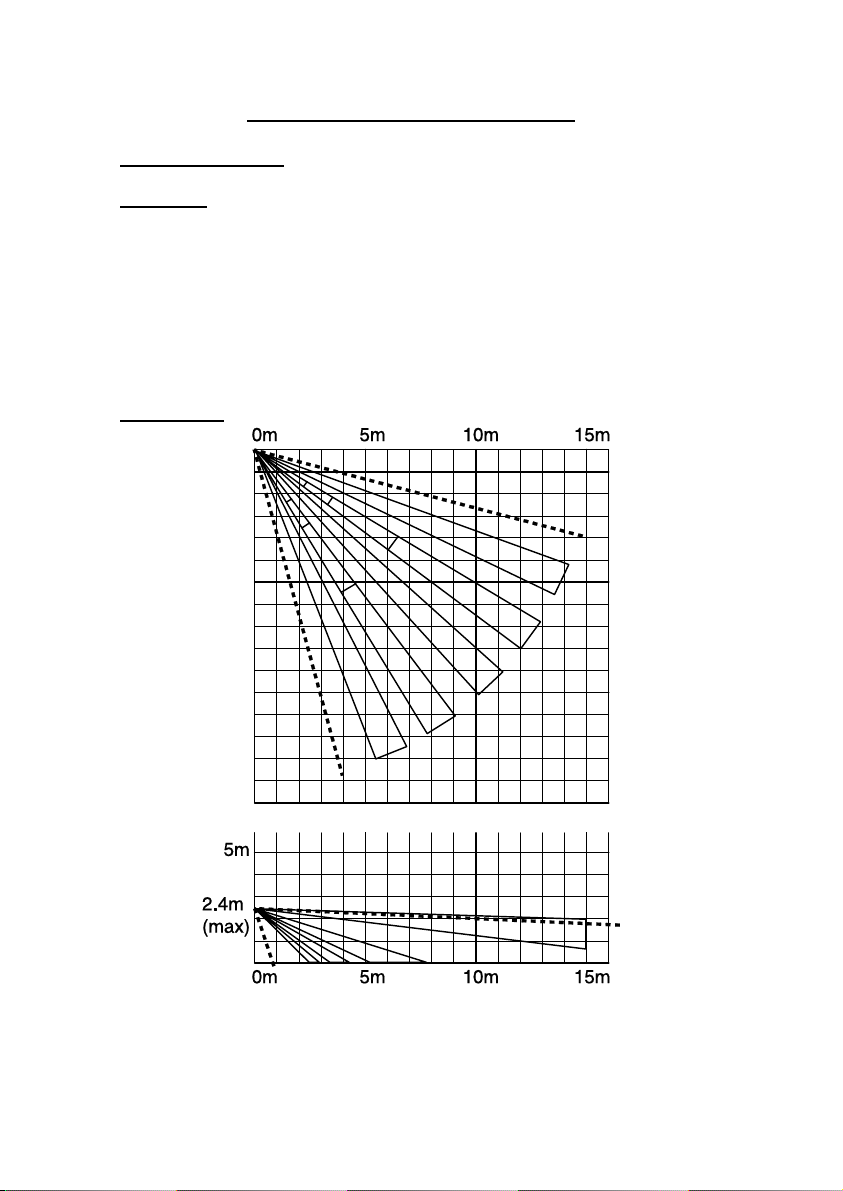
Coverage.................................................................................................. 4
Radio ....................................................................................................... 5
Power Supply ............................................................................................ 5
Electromagnetic Compatibility...................................................................... 5
Electrical Safety......................................................................................... 5
Compliance Statements .............................................................................. 5
Compatible Equipment ............................................................... 5
Installation.................................................................................6
Tools Required .......................................................................... 6
Site Survey .............................................................................. 6
Batteries .................................................................................................. 6
Learning................................................................................................... 6
Site Survey............................................................................................... 7
Fit Back Plate............................................................................ 7
Fitting a Wall Tamper ................................................................................. 8
Fitting a Corner Wall Tamper ....................................................................... 9
Completing the Physical Installation ............................................10
Programming............................................................................11
Programming Overview .............................................................11
Set Up Control Unit’s Own IP Address..........................................12
Set Up the IP Address of the ARC ...............................................13
Setting Up an Email Address ......................................................14
Setting up for Downloader .........................................................14
Enabling the Photo PIR..............................................................15
Testing .....................................................................................16
Photo PIR Testing and Lockout ...................................................16
PIR Walk Testing ......................................................................16
Checking Photo Coverage ..........................................................17
USB Connection....................................................................................... 17
Ethernet Connection................................................................................. 18
Uploading Pictures to Downloader .............................................................. 18
Dealing with Radio Interference..................................................19
Maintenance ............................................................................19
Service................................................................................................... 19
Programming Information Required.........................................20