COP-USA SDDVR-WF User manual

H.264 Wi-Fi IP High Resolution
Smoke Detector Color Camera
3G Wifi IP Camera is Accessible from Anywhere in the World by Internet
* 1/3’’ Color CCD
High Resolution Camera
* 540 TVL 0.001LUX (SDNR) Slow-shutter
* Audio Video Intercom by Wi-Fi / Ethernet
* H.264 Algorihm hardware compression
* Easy Recording Setup by Internet
* Functional Smoke Detector Camera
* DC12V 1A
MONITOR
Reset
Camera
MIC
Video or DVR
DC12V 1A
Internet
SDDVR-WF
InterNet
Router
InterNet
Wireless Router
* Specifications are subject to change without notice
** Designed in U.S.A.
* 3.7mm Pinhole Lens

Basic step for wifi setup
First connect your wifi device and computer to the switch or router using the
network cable.
Please note: the default ip address is (192.168.0.233)
The LAN ip address of your device is:
IP address 192.168.0.233
Subnet mask 255.255.255.0
Default gateway 192.168.0.1
Now you have to manually assign your computer LAN ip address.
To do this, please right click on my network places icon located on your desktop then click on properties.
Now right click local area connection, then click on properties.
Under local area connection screen in the general tab, click on internet protocol (tcp/ip) then click on
properties.
On internet protocol (tcp/ip) properties, click on use the following ip address and assign the following
address below.
Your computer ip address should be:
Ip address 192.168.0.200
Subnet mask 255.255.255.0
Default gateway 192.168.0.1
After completing all of the steps above, you’re now ready to configure your wifi.
First you need to launch your internet explorer only (not compatible with firefox browser)
Clear out the address bar than type the following ip address in your address bar (192.168.0.233)
It will display the login screen, before you login please install the ocx plugin first!!!!!!!
Login name: admin
Password: admin
Once you login successfully, please click the network setup on the left off your screen.
Now click on wireless nic to configure and input your router information.
On the wireless nic tab
1. Enter your router ESSID (router name)
2. Select encrypt (input your security code for your router)
3. Wep key (input your security key to gain access to the router)
4. Choose the options (use specific ip)
5. Input your ip address: xxx xxx xxx xxx
6. Netmask: xxx xxx xxx xxx
7. Default gateway: xxx xxx xxx xxx
8. After filling in your entire router information, click ok then click on reboot tab to your left.
9. Once your device is rebooted, please give it 45 seconds before disconnecting the network cable.
You are now able to access your device wirelessly, through the ip address you have assigned.

1
Network Video Server
᧤
V1.1
᧥
User guide
June, 18, 2007

2
The aim of this handbookis to help user managing and using the series of DVS products made by
our company. In order to achieve highly performance of products, you may need to know basic network
knowledge before reading this handbook. You can also find more information you need from online
help.
The notice tag in this handbook
Caution! — A potential danger of server damage.
Important! —An operation that will severely impaired the capability of server.
It is recommended do not use these operations unless you are quite understanding them.
Intellectual property rights
All products in this handbookhave entire independent intellectual property rights. Any individuals
or organizations are not allowed to infringe upon any products or reproduce documents of products
made by our company.
Support and service
For any technical problems, please contact your local vendor. If your problem can not be solved
immediately, the problem will be sent to our technical department to ensure it can be solved as soon as
possible. You may also find your answer via following methods:
1
ᇬ
Download the latest version installation package to upgrade application by accessing our website.
2
ᇬ
Find answer from FAQ page in our website.
3
ᇬ
Contact technical support personnel via IM software.

3
Network video server user guide v1.1
June, 18, 2007
Index
Index .......................................................................................................................................................................... 3
1. Product Overview.

4
2. SD DVR series video server installation......................................................................................................... 8
2.1. Hardware installation............................................................................................................................. 8
2.1.1. Installation steps ........................................................................................................................ 8
2.1.2. Notice......................................................................................................................................... 8
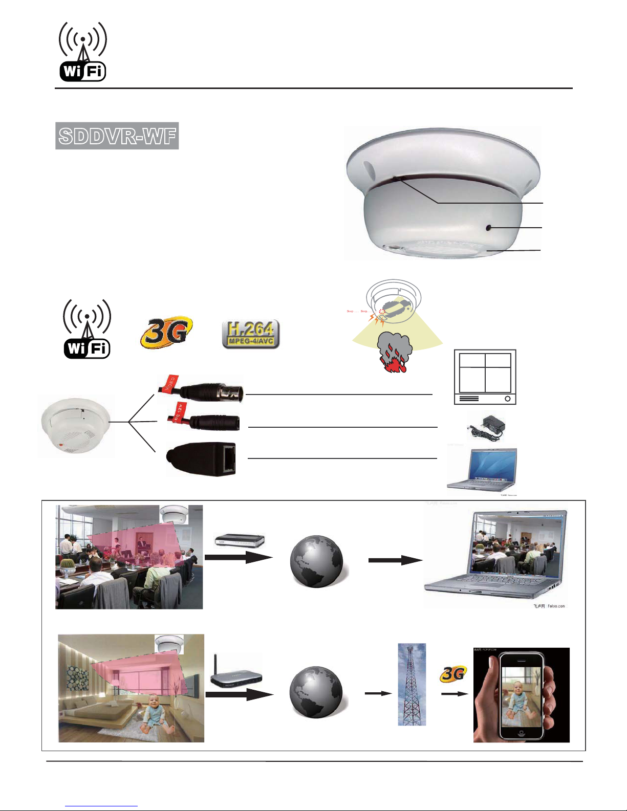
2.2. Device panel description........................................................................................................................ 9
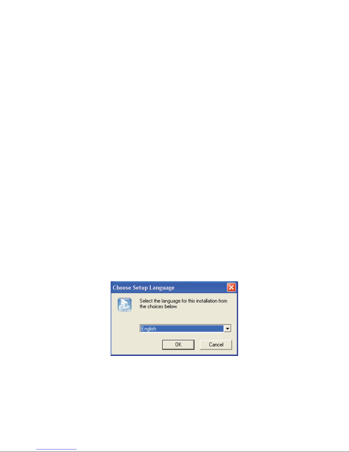
2.3. Client software installation .................................................................................................................. 10
3. Video server parameter configuration.............................................................................................................. 14
3.1. Video and image setting....................................................................................................................... 15
3.1.1. Video attribute setting .............................................................................................................. 15
3.1.2. Image setting............................................................................................................................ 16
3.1.3. Advanced image setting skill................................................................................................... 17
3.2. OSD/MASK setting ............................................................................................................................. 19
3.3. Audio setting........................................................................................................................................ 21
3.4. System networksetting........................................................................................................................ 22
3.5. PTZ, COM setting ............................................................................................................................... 24
3.5.1. PTZ device management ......................................................................................................... 24
3.5.2. PTZ protocol setting ................................................................................................................ 24
3.5.3. RS232 serial port parameter setting......................................................................................... 26
3.5.4. PTZ management FAQ ............................................................................................................ 26
3.6. Alarm and event management ............................................................................................................. 26
3.6.1. Video motion alarm management ............................................................................................ 27
3.6.2. Video loss alarm management ................................................................................................. 28
3.6.3. Sensor input management........................................................................................................ 29
3.6.4. Sensor output setting................................................................................................................ 31
3.7. PPPOE&DDNS setting........................................................................................................................ 32
3.8. Center platform connection setting...................................................................................................... 32
3.9. System setting...................................................................................................................................... 33
3.10. User rights setting ................................................................................................................................ 38
4. Client software operation................................................................................................................................. 39
4.1. System login, lockand logout.............................................................................................................. 39
4.1.1. System login ............................................................................................................................ 39
4.1.2. System lock.............................................................................................................................. 41
4.1.3. System logout .......................................................................................................................... 42
4.2. System setting...................................................................................................................................... 42
4.2.1. Server management.................................................................................................................. 42
4.2.2. User management .................................................................................................................... 48
4.3. Server login.......................................................................................................................................... 50
4.3.1. Reload server ........................................................................................................................... 50
4.3.2. Server login.............................................................................................................................. 50
4.3.3. Server logout............................................................................................................................ 51
4.4. Video browse and control .................................................................................................................... 52
4.4.1. Video browse ........................................................................................................................... 52
4.4.2. Sound play control................................................................................................................... 54

5
4.4.3. PTZ control.............................................................................................................................. 54
4.4.4. Preset position.......................................................................................................................... 55
4.5. Audio intercom .................................................................................................................................... 56
4.5.1. Client request intercom............................................................................................................ 56
4.6. Video grouping, viewing...................................................................................................................... 57
4.6.1. Video grouping setting............................................................................................................. 57
4.6.2. Video grouping view................................................................................................................ 61
4.6.3. Video grouping cyclic switch................................................................................................... 62
4.7. Image capture....................................................................................................................................... 62
4.7.1. Capture setting ......................................................................................................................... 63
4.7.2. Manual capture ........................................................................................................................ 63
4.7.3. Alarm capture .......................................................................................................................... 64
4.7.4. Capture images browse............................................................................................................ 64
4.8. Video record......................................................................................................................................... 65
4.8.1. Record setting .......................................................................................................................... 65
4.8.2. Timer record ............................................................................................................................ 66
4.8.3. Manual record.......................................................................................................................... 67
4.8.4. Alarm record............................................................................................................................ 68
4.8.5. Record status checking ............................................................................................................ 72
4.8.6. Video data search ..................................................................................................................... 74
4.9. Alarm management.............................................................................................................................. 74
4.9.1. Alarm management setting ...................................................................................................... 74
4.9.2. Real time event ........................................................................................................................ 76
4.9.3. History event............................................................................................................................ 78
5. Frequent problems ........................................................................................................................................... 78
6. Appendix ൕspecs............................................................................................................................................ 80
7. Appendix ൖfactors influencing system capability......................................................................................... 82

2*,!.
0/7%2$#6INPUT$#CORD
6IDEO".#
#AMERA
0RODUCT/VERVIEW
3$$62VIDEOSERVERSINDEPENDENTOF0#USEEMBEDDEDREALTIMEMULTITASKOPERATION
SYSTEM24/3WITHEMBEDDEDPROCESSOR4HECODEOFSERVERSISSTOREDINFLASH)TWILLREALIZEARELIABLE
ANDEFFICIENTOPERATIONOFTHESYSTEM
)TALSOUSE-0%'(COMPRESSIONFUNCTION4HECOMPRESSEDSTREAM
TRANSMITSVIANETWORK4HEREALTIMEVIDEOANDAUDIOCANBEPREVIEWEDBYNETWORK3ERVERSSUPPORT
STREAMPROTOCOL24024#02430)%BROWSETWOWAYAUDIOINTERCOMMULTILANGUAGEETC
"ASICFUNCTION
s-0%'AND(COMPRESSIONTECHNIQUEWITHHIGHCOMPRESSIONRATEANDFLEXIBLEPROCESSING
s3UPPORTCHANNELSONLINEMONITORINGSUPPORT#3MODETHEWEBSERVEREMBEDDEDINTHEVIDEO
SERVERPROVIDESCONVENIENT"3ACCESS
s-ULTILEVELUSERRIGHTSMANAGEMENTENSURINGSYSTEMSECURITY
s3UPPORT23AND23INTERFACEWHICHCANSUPPORTTHIRDPARTY04:DEVICEOROTHERSERIAL
DEVICE3UPPORTTRANSPARENTTRANSMISSIONANDTHEPARTICULARFUNCTIONMADEBYOURCOMPANYVIRTUAL
MATRIX
s0OWERFULALARMMANAGEMENTANDEVENTPROCESSINGINCLUDINGVIDEOLOSTVIDEOMOTIONALARM
SENSORINPUTSENSOROUTPUTALARMLINKAGEALARMAUTOMATICCONNECTIONALARMLOGCANHELPYOU
HANDLEVARIOUSCONTINGENCIESCHANNELSONOFFTRIGGERSENSORINPUTCHANNELSSENSOROUTPUT
ADDITIONALALARMDEVICESSUCHASALARMHOSTACCESSCONTROLSYSTEMETCCANCONNECTWITHSERVERVIA
#/-PORT
#OMPRESSIONPROCESSINGFUNCTION
s3UPPORT/3$DATETIMEDISPLAYPOSITIONANDGRAYSCALESETTINGDATATIMEAUTOMATICDISPLAY
.ETWORKABILITY
s3UPPORTA--COMPATIBLE%THERNETPORT
s3UPPORT4#0)0PROTOCOLSOFTWAREORBROWSERPARAMETERCONFIGURATIONREALTIMEVIDEOANDAUDIO
BROWSESERVERSTATUSCHECKINGNETWORKALARMCOMPRESSIONSTREAMSAVINGVIANETWORK
s2EMOTEUPGRADEANDMAINTENANCEVIANETWORK

7
2. SDDVR series video server installation
2.1. Hardware installation
2.1.1. Installation steps
1. Unpackthe case and checkif all things in the case are in good condition
2. Take out devices which will be installed
3. Connect devices TO 0OWER AND .ETWORK ,INE
2.1.2. Notice
Please carefully read this part. For any further enquiry please contact us.
1. Please checkout all things in the LIST you received ARE THEPACKAGE
2. Please read user handbookcarefully before the installation
3. Please switch off all power supply of devices before the installation of 3$$62 series
video server
4. Checkthe voltage of power supply to avoid damageSTOTHEDEVICE
5. Installation environment: please do not use device in high temperature or wet environment.
Please note that keep proper ventilationTOTHEUNIT

8
6. IN᧶2 channels sensor input the rising or falling edge of level of channel S1 or channel S2 can
trigger alarm. The method of application is that connects port S1 or S2 with a 47K Ohm resistance,
and then connects with a 12V power supply, and parallel connects with the alarm flip-flop.
Connect one side of flip-flop with S1 or S2, connect another side of flip-flop with panel power
GND or +12V power terminal.
7. output power: GND, +12V
8. RS485᧶RS485 connection terminal+, -
9. IO extension port, user-defined usage; GND use the output power GND
10. RS232᧶RS232 connection terminal T: sending connection terminal, R: receiving connection
terminal; RS232 use output power GND terminal
11. MIC᧨AOUT᧶audio intercom input, output, connect with passive device
12. VIN᧶video input, 1 channel video input, standard BNC connector Jack
13. AOUT᧶audio output, connect with active device
14. AIN᧶Audio input, 1 channel audio input, standard BNC connector Jack
2.3. Client software installation
Run setup on windows, double clickyour left mouse button, it will be an “installation wizard” dialogue
box, as following figure:
Figure 2-1 Choose installation language
Choose language and click“Yes”, there will be a dialogue box:

9
Figure 2-2 Installation confirmation
Click“next”, there will be a dialogue box:
Figure 2-3 agreement license
Click“Yes”, there will be a dialogue box:

10
Figure 2-4 Choose installation folder
Choose installation folder, click“next”, there will be a dialogue box:
Figure 2-5 Start to copy files
Click“Next”, move to the installation process

11
Figure 2-6 Start the installation
When the installation is finished, there will be a dialogue box:
Figure 2-7 Installation complete
Click“Finish” button, client software was installed into the system default directory and there will
be a “NetView” program group on the “Start”Æ”Program” of the windows system

12
3. Video server parameter configuration
There are following types of NVS-6000 video server parameter configuration:
1)ᇬSet DVS parameter via client software (connect DVS with computer via network)
2᧥ᇬSet DVS parameter via IE (connect DVS with computer via network)
NVS-6000 video server supports networkpreview, parameter setting and remote control via
software and IE
Use setting tool
When you login the server successfully with IE, you can use the convenient setting tool provided
by us to configure the video server. Click“parameter setting” with left mouse button, configuration tool
will pop-up a new page, displayed as following:
Figure 3-1 Server setting

13
3.1. Video and image setting
Notice
᧶
When setting the video and picture's parameters of the 2 or 4 channels device, it will restart
automatically.
Video and image setting interface is displayed as following:
Figure 3-2 Channel setting
3.1.1. Video attribute setting
Video attribute setting includes video mode, color and definition setting
¾ᇹVideo ModeᇺVideo Mode includes PAL and NTSC standard, each channel can choose different
system(please note that the 4-channel server can only choose a same system for each channel)
¾ᇹColor SetupᇺColor Setup includes the brightness, contrast and hue. The left of the setting bar is
the minimum value, you can easily drag the bar control to change value by mouse. For fine tuning
you can use the direction key of keyboard.

14
¾ᇹDefinitionᇺDefinition includes a 4-level definition setting of video. The left of the setting bar is
the minimum value, you can easily drag the bar control to change value by mouse. For fine tuning
you can use the direction key of keyboard.
3.1.2. Image setting
Image setting includes the Video Format (image resolution), Encode Audio, Frame Rate, I Frame
interval, maximum quantification coefficient, minimum quantification coefficient, and bit rate settings.
(Details are described in the next part “Advanced image setting skill”)
¾ᇹVideo FormatᇺImage setting. It is adjusting the resolution, please refer to the table:
resolution PAL system NTSC system
D1(4CIF) 720*576 720*480
HD1(2CIF) 720*288 720*240
CIF 352*288 352*240
QCIF 176*144 176*120
Notice: 1-channel products or 2-channel products support D1 (4CIF) resolution. 4-channel series
products support CIF resolution.
¾ᇹEncode AudioᇺSelect the encoding audio item of checkbox if you need audio. Uncheckthe
encoding audio item if you only need video.
¾ᇹFrame RateᇺIt means how many frames the encoder is encoding per second. For details please
refer to table 1.
¾ᇹI Frame InvᇺIt means the number of frame P or frame B between key frames (frame I)
¾ᇹRate TypeᇺWhen the VBR(Variable Bit rate) is chose, the video server will automatically
choose a proper stream according to the complex and movement condition of images and the
image quality is set by user, but the “stream rate” will not exceed. When the CBR (Constant Bit
rate) is chose, the video server will control the “stream rate” in the setting.
¾ᇹImage QualityᇺImage quality. It is an important parameter which controls image quality; it can
be set in 5 levels. For setting please refer to “Advanced image setting skill”

15
¾ᇹBit Rateᇺ“Bit Rate” means the amount of stream bit encoding by encoder in a second, the unit
of stream rate is bps, namely bits per second. The range of stream rate is from 16kto 4096k, please
note that the unit kmeans 1000, for example 4096kmeans 4096000bps, the encoder will use
4096000bps stream rate to encode video.
For more details of setting of the above part please refer to the following “Advanced image
setting skill”
3.1.3. Advanced image setting skill
Image setting is an important part in the server setting because it will affect the system ability, it has
close relationship with the video quality and networkability. The aim of image setting is to make it
conveniently suitable for various networks.
Bit stream and frame rate settings are providing in system, but it is hard to suit various networks
with only several default values. Consequently, some advanced settings are provided for user to ensure
the video quality while utilizing networkeffectively.
The image settings including
ᇹBit Rateᇺ,ᇹFrame Rateᇺ,ᇹI Frame Invᇺ,ᇹRate typeᇺ,ᇹImage
QualityᇺandᇹDefinitionᇺare what we concern about.
Now we will introduce meaning, effect to other settings and networkability of each setting
respectively.
¾Bit Rate
It means the size of stream bit encoding by encoder per second. The unit is bit per second. This
setting is the main factor affects the bandwidth of networkand other settings. The bandwidth utilizing
will increase when the bit rate increase. Thus CBR (Constant Bit rate) setting according to the
bandwidth is suitable for the networkbandwidth limitation situations. In the same quality situation, bit
rate will be affected by settings including frame rate, I frame Inv, rate type, image quality, and
definition. Please refer to following introduction for details. This parameter is valid when the “Rate
Type” is set as CBR (Constant Bit rate).
¾Frame Rate
It means the maximum number of frames that encoder encodes per second, with unit frame per
second. this setting has three functions, firstly the number of frames encoder encoding per second is set
by this setting, secondly when the stream rate is CBR (Constant Bit rate), when the frame rate changed,
for example decreased, because the encoder need to keep the current code stream setting, thus it will
enhance the frame quality according to the current code stream setting. It means, when the code stream
is VBR (Variable Bit rate), the decreasing of frame rate will enhance the quality of video and keep the
same frame rate value. The video quality will reduce conversely. Thirdly, when the same quality is kept,

16
the increasing frame rate will make the image display smoother and stream rate increasing. Conversely,
the image will become discontinuous and stream rate decrease.
¾I Frame Inv
It means the number of frame P or frame B between key frames (frame I). Generally, the default
value of this parameter is 25 and does not need to be changed. When the stream rate is settled, the
increasing of this value will make the quality of video better. When the video keep the same quality,
this value increasing will make stream rate increased. Conversely, the stream rate will decrease.
¾Rate Type
when the VBR(Variable Bit rate) is chose, the front end will automatically choose a proper stream
according to the complex and movement condition of images and the image quality set by user, but the
“Bit Rate” will not exceed. When the CBR (Constant Bit rate) is chose, the front end will control the
“Bit Rate” in the setting.
¾Image Quality
It is an important parameter which controls image quality; this parameter is valid when the “Rate
Type” is set as VBR (Variable Bit rate).
¾Definition
Definition controls the sharpness of image, setting with 4 levels: 1 for lowest, 4 for highest. When
the video keep the same quality, the higher the definition is, the higher the stream rate will be,
conversely, the stream rate will decrease. When the stream rate is constant as a low value, the higher
the definition is, the lower the image quality will be. When the stream rate is a high value, the higher
the definition is, the better the image quality will be.
To sum up, please refer to our reference value for various conditions and the information giving
above to adjust the image setting. You can make adjusting according to the above description if the
quality of video is not satisfied.
reference
setting attribute frame
rate rate type image
quality Bit rate resolution
CBR(Constant
Bit rate)
CBR(Constant
Bit rate) 25 CBR(Constant
Bit rate) invalid set according
condition
set according
condition
LAN VBR(Variable
Bit rate) 25 VBR(Variable
Bit rate) best unlimited
set
according
condition
ADSL-
upload 512k
CBR(Constant
Bit rate) 12 CBR(Constant
Bit rate) invalid 384kD1
ADSL-upload CBR(Constant 12 CBR(Constant invalid 512kD1

17
1M Bit rate) Bit rate)
ADSL-upload
2M
CBR(Constant
Bit rate) 25 CBR(Constant
Bit rate) invalid 768kD1
best VBR(Variable
Bit rate) 25 VBR(Variable
Bit rate) best unlimited
set according
condition
good VBR(Variable
Bit rate) 25 VBR(Variable
Bit rate) good unlimited
set according
condition
normal VBR(Variable
Bit rate) 25 VBR(Variable
Bit rate) normal unlimited set according
condition
bad VBR(Variable
Bit rate) 25 VBR(Variable
Bit rate) bad set according
condition
set according
condition
worst VBR(Variable
Bit rate) 25 VBR(Variable
Bit rate) worst set according
condition
set according
condition
user-defined user-defined ᧩᧩᧩᧩
Notice: pleas slightly adjust values referring to above reference values according to the system
condition. You can make necessary adjusting according to the description of each setting if you
have strict requirements for the image quality or the bandwidth.
3.2. OSD/MASK setting
The “OSD setting” shown as following figure includes the OSD/MASK setting. In the setting “෭”
in “႒” means enabling the corresponding overlay option function, contrarily disabling the
corresponding function.

18
Figure 3-3 OSD setting
¾ᇹDisplay information settingᇺThis setting achieves the characters overlay function, including
date overlay, time overlay, channel description overlay, and font display. Date and time will be
displayed on the top left of the preview image. Channel description displays the location with
coordinate X (0~720) and Y(0~576)
¾ᇹMask zone settingᇺ᧶This setting achieves the video masksetting function on specific zone.
Click“Covering” by left mouse button, a setting dialogue box will pop-up. Then draw a zone
where you would like to maskon the image with left mouse button and click“Ok”, the setting is
finished. If you would like to cancel the masksetting, click“Clear” with left key and click“Ok”
directly.
Table of contents
Other COP-USA Smoke Alarm manuals