Swegon GOLD ELQZ-2-428-2 User manual

GB.ELQZ428.050101
Specifications are subject to alteration without notice. www.swegon.se 1
Installation Smoke Detector
ELQZ-2-428-2, GOLD
General
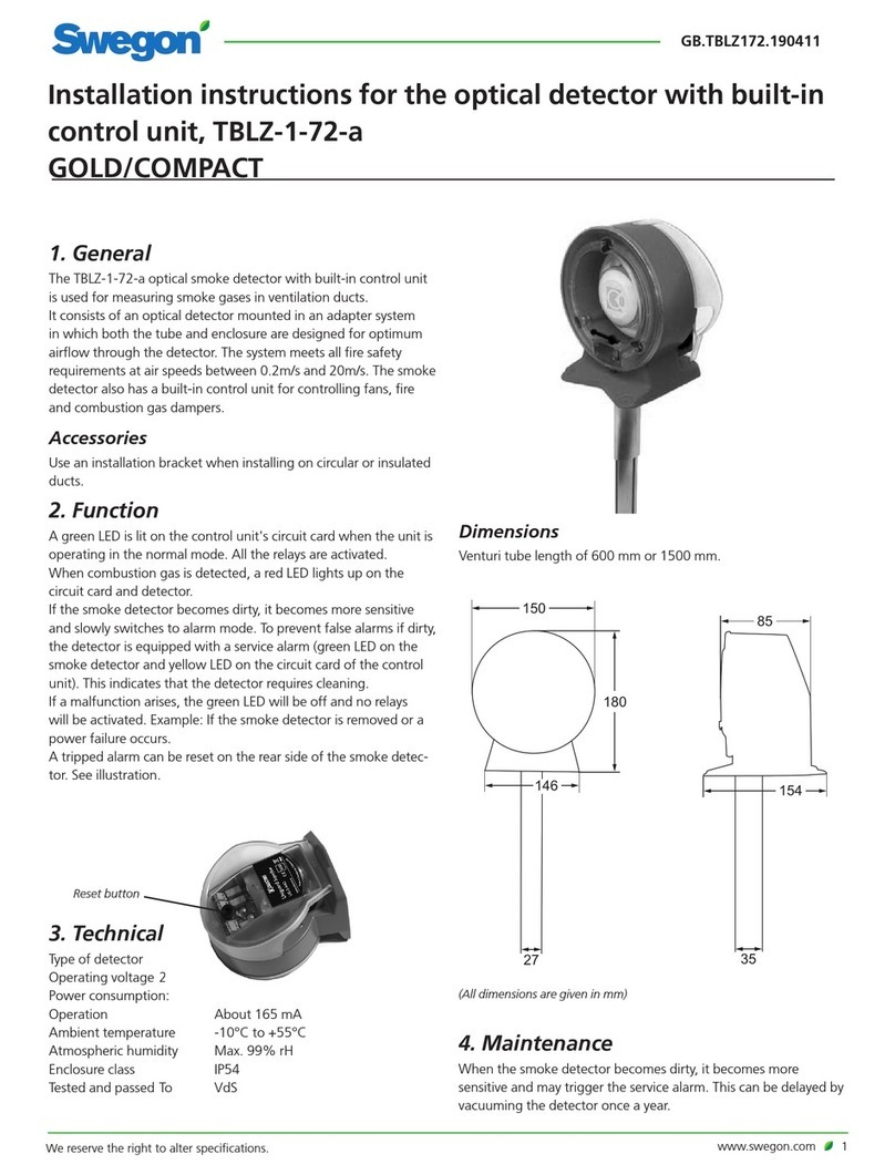
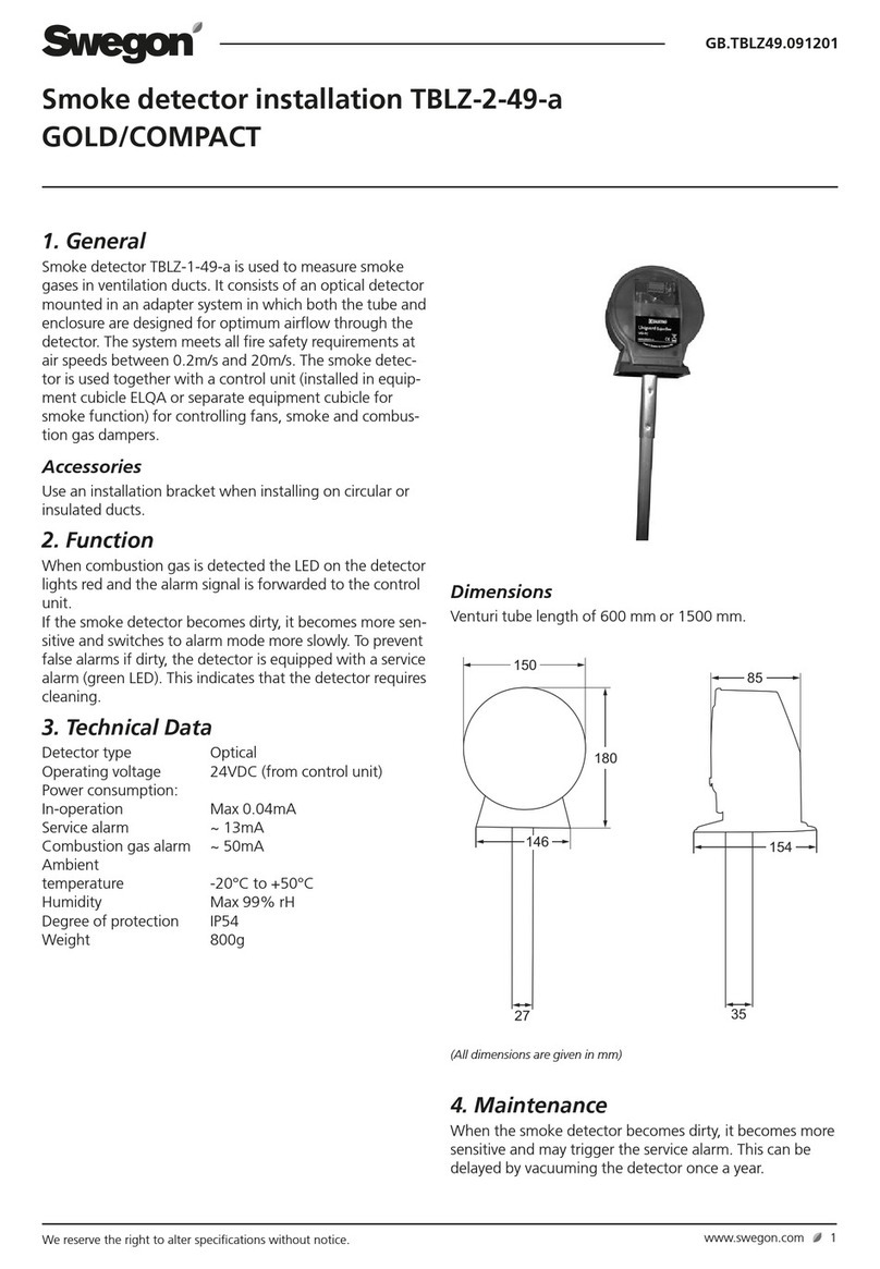
The ELQZ-2-428-2 smoke detector is used for measuring
any smoke present in ventilation ducts. It consists of an
ionising detector mounted in an adaptor system where
both the tube and enclosure are designed for optimum
airflow through the detector. The system meets all the
fire safety requirements for air velocities between 0.2 m/s
and 20 m/s. The smoke detector is used together with a
control unit (fitted inside an ELQA equipment cubicle or a
separate equipment cubicle for the smoke detection and
warning function) for controlling fans, fire and smoke
dampers.
Operation
If any smoke is detected, a red LED on the detector lights
up and the detector transmits an alarm signal to the con-
trol unit.
Any accumulation of impurities in the smoke detector will
make it more sensitive and gradually approach its alarm
condition. To avoid unnecessary alarms caused by fouling,
the detector is equipped with a service alarm (green LED).
When lit, this LED indicates that the detector ought to be
cleaned.
Tecnical details
Type of detector Ionising
Power supply 24VDC (from control unit)
Power consumption:
In-operation Max 0,04mA
Service alarm ~ 13mA
Smoke alarm ~ 48mA
Permissible
ambient temperature -20°C to +50°C
Permissible humidity Max 99% rH
Inclosure Class IP54
Weight 800g
Accessories
The ELQZ-1-428-2-1 Mounting bracket should be used for
mounting the detector on a circular or insulated duct.
Maintenance
Whenever the smoke detector becomes fouled, it will be
more sensitive and may trip the service alarm. This situa-
tion can easily be delayed by vacuum cleaning the detec-
tor once a year.
Dimensions
Venturi tube length 600 mm.
(All dimensions in mm)

GB.ELQZ428.050101
Specifications are subject to alteration without notice.
2 www.swegon.se
MIN 3xdhMIN 5xdh
GX GX
MIN 3xdhMIN 5xdh
GX GX
MIN 3xdhMIN 5xdh
GX GX
MIN 3xdhMIN 5xdh
GX GX
MIN 3xdhMIN 5xdh
GX GX
MIN 5xdh
GX
MIN 3xdh
GX
MIN 5xdh
GX
MIN 3xdh
GX
GX
MIN 3xdh
GX
GX
MIN 3xdh
MIN 5xdh
d = D
Ø D
h
d =
h
2xHxB
H+B H
B
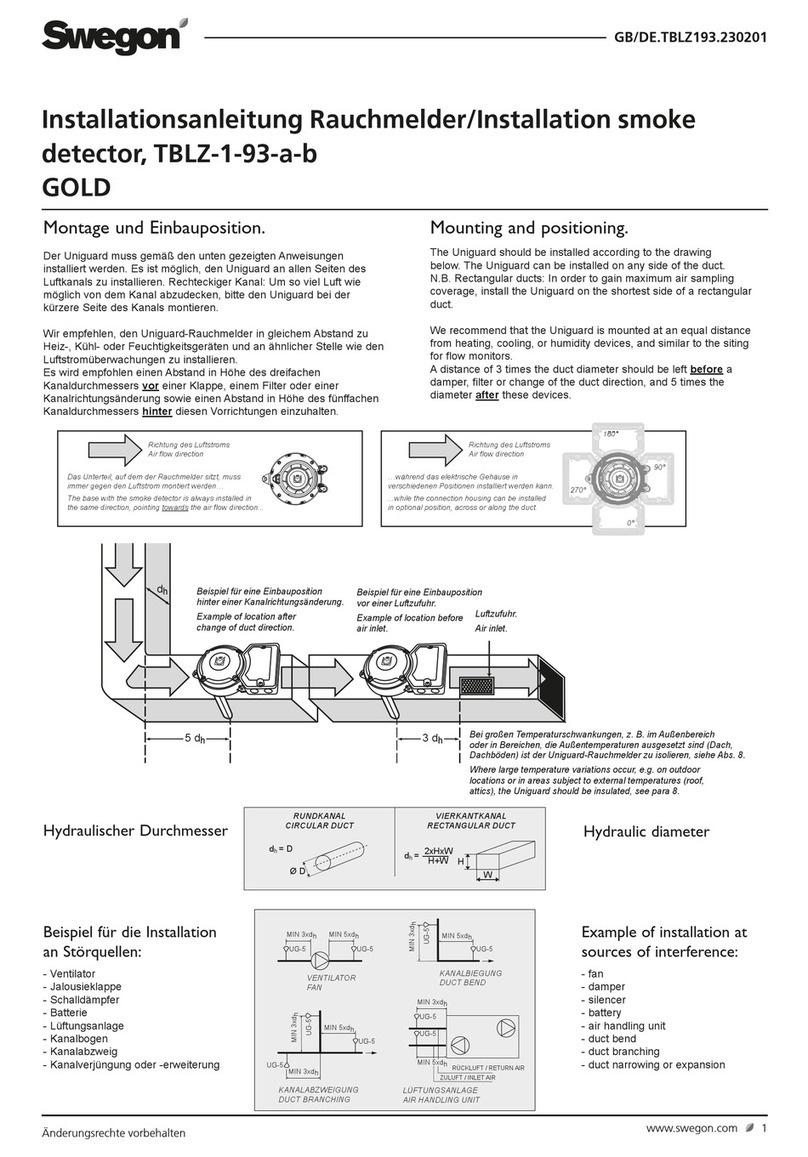
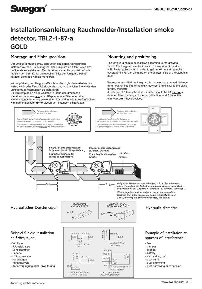
Installation and Location
Install the smoke detector with the airflow direction arrow
on its cover pointing in the direction of airflow through the
ducting. The detector can be mounted on the side or top of
the duct for vertical or horizontal air flow.
If the ambient temperature varies radically, for example
outdoors or in cold attics, insulate the detector to protect it
from the ambient air and prevent the formation of conden-
sation inside the detector housing.
To ensure satisfactory smoke detection, the smoke detector
should be located at a distance, in the direction of airflow,
that is equivalent to at least 3 x the hydraulic diameter of
the duct upstream of the nearest source of disturbance
in the ducting (see the examples of sources of disturbance
below). If it is located downstream of the nearest source
of disturbance, its distance from this source should be equi-
valent to at least 5 x the hydraulic diameter of the ducting.
Hydraulic diameter
CIRCULAR DUCT
RECTANGULAR DUCT
AIR HANDLING UNIT
MIN 3xdhMIN 5xdh
GX GX
MIN 3xdhMIN 5xdh
GX GX
MIN 3xdhMIN 5xdh
GX GX
MIN 3xdhMIN 5xdh
GX GX
MIN 3xdhMIN 5xdh
GX GX
MIN 5xdh
GX
MIN 3xdh
GX
MIN 5xdh
GX
MIN 3xdh
GX
GX
MIN 3xdh
GX
GX
MIN 3xdh
MIN 5xdh
d = D
Ø D
h
d =
h
2xHxB
H+B H
B
Examples of sources of disturbance
FAN DAMPER
SILENCER COIL
BEND
BRANCH
ADAPTER EXTRACT AIR
SUPPLY AIR
AIR HANDLING UNIT

GB.ELQZ428.050101
Specifications are subject to alteration without notice. www.swegon.se 3
�
�
IMPORTANT!
The arrow on the plastic cover must
point in the same direction as that of
the air flowing through the duct.
1
2
Drill an opening in the duct. • 35 mm dia. opening for smoke detector without mounting bracket.
• 50 mm dia. opening for smoke detector with mounting bracket (see item 10).
3
Do not cut this end!
• Measure the ventilation duct.
• Cut the tube to an appropriate length, if needed.
• The tube should penetrate 90% of the duct diameter
into the duct.
• Insert the end plug.
End plug.
• Lock the tube in
position by means
of the stop screw.
• Slip the seal onto the tube.
• Insert the tube in the bottom of the
detector housing.
4
• Mount the tube and the detector on the duct.
• Secure the detector housing at the 3 points indicated by
the arrows.

GB.ELQZ428.050101
Specifications are subject to alteration without notice.
4 www.swegon.se
5Flow indicator.
CAUTION!
The indicator doesn't rotate;
it rocks. If the indicator
doesn't move at all, it is advisable
to consider relocating the detec-
tor.
6Insert the block.
7Electric wiring.
Connect the electric
wiring as shown in the
wiring diagram.
If only one smoke detector is connected to the system, install
the final resistor (2,2kΩ) in this detector.
If several smoke detectors are to be connected to one control
unit, wire the final resistor (2,2kΩ) in the last detector in the
loop. Fit only one resistor per loop!

GB.ELQZ428.050101
Specifications are subject to alteration without notice. www.swegon.se 5
8Performance checks.
9
Check that the detector opera-
tes correctly. Expose the detec-
tor to smoke from a match or a
suitable spray for testing smoke
detectors.
Secure the cover by
means of screws.
Fit the cover on the detector.
Do not drill any holes in the plastic cover for
fitting identification plates or the like. Doing
so will cause leakage, which will seriously
impair detector performance.

GB.ELQZ428.050101
Specifications are subject to alteration without notice.
6 www.swegon.se
Beslaget levereras plant.
Beslaget är lätt att böja/forma så att det�
passar runda eller plana kanaler.
Rund kanal.
Gummi-�
tätning. Gummi-�
tätning.
Isolerad plan kanal.
Håltagning�
Ø 50 mm.
Fäst �
beslagets�
ben på kanalen.
ELQZ-1-428-2-1 Mounting bracket for a circular duct or an insulated rectangular duct.
The mounting bracket enables the detector to be installed on a duct
having a diameter as small as 100 mm.
FINAL INSPECTION
Fault tracing.
The smoke detector indicates a service alarm.
• The detector has become fouled and needs to be clea-
ned. This can appropriately be done by vacuum cleaning
or by carefully blowing surfaces clean with compressed air.
• The service alarm may trip sooner than expected if the
newly installed ducting hasn’t been properly cleaned
before the system is commissioned.
The smoke detector initiates an alarm when no
smoke is present.
• The smoke detector has been located where condensa-
tion can form inside it, such as outdoors, in a cold attic, a
kitchen or the like.
An alarm is indicated by the control unit only.
• Measure the resistance of the loop (2,2kΩ) from the
control unit.
•
Check that the control unit is OK by wiring the final resistor
to the smoke detector output on the control unit.
•
Use a voltmeter to check that 24 V DC with the correct
polarity is present in the socket below the detector.
10
The bracket is supp-
lied completely flat.
The bracket is easy to bend/form to
fit on circular or flat duct surfaces.
Opening: Ø 50 mm
Secure the legs
of the bracket
to the duct.
Circular
duct
Rubber seal
Rubber seal Insulated
rectangu-
lar duct
• Make sure thatthe arrow on the detector cover points in the direction of airflow.
• Check that the cover and its gasket seals properly against the base and that nothing is lodged in between
them, such as insulation.
• Check that the plug is properly seated in the test hole.
• Check that the flow indicator indicates airflow (is rocking).
• It is advisable to test the performance of the detector in full scale.
This manual suits for next models
1
Table of contents
Other Swegon Smoke Alarm manuals