Yaesu FT-4VR User manual

VHF FM TRANSCEIVER
Operating Manual
FT- 4VR
FT- 4VE

Introduction ....................................................................................................................... 1
About this manual ............................................................................................................ 1
Quick Guide ...................................................................................................................... 2
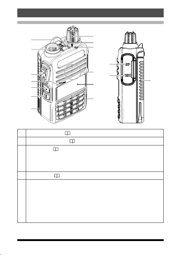
Controls & Connections .................................................................................................. 3
Transceiver ..................................................................................................................... 3
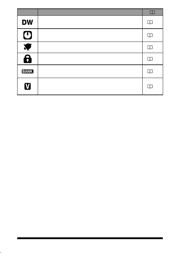
Display ............................................................................................................................ 5
The Keypad Functions ................................................................................................... 7
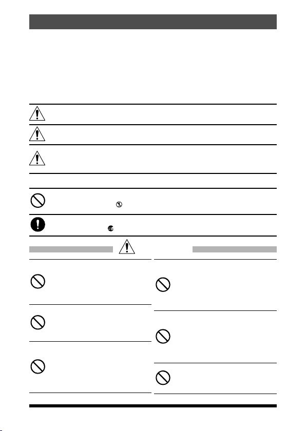
Safety Precautions (Be Sure to Read) ............................................................................ 8
Preparation ...................................................................................................................... 11
Installing the Antenna .................................................................................................. 11
Attaching the Belt Clip ................................................................................................. 11
Installing the Battery Pack ........................................................................................... 11
Removing the Battery Pack ......................................................................................... 11
Supplied Accessories and Options .............................................................................. 12
Supplied Accessories .................................................................................................. 12
Available Options ......................................................................................................... 12
Charging the Battery Pack ............................................................................................. 12
Charging the Battery Pack using the Rapid Charger (SBH-22) ................................. 12
Operation ......................................................................................................................... 13
Switching between the VFO-A and VFO-B ................................................................. 13
Tuning to a Frequency ................................................................................................. 13
Changing the Frequency Step .................................................................................. 14
Adjusting the squelch setting ....................................................................................... 14
Transmission ................................................................................................................ 14
Changing the Transmission Power Level .................................................................... 15
Locking Keys and PTT switch ...................................................................................... 15
Programmable key [P1]/[P2] ........................................................................................ 16
Repeater Operation ........................................................................................................ 17
Communicating Via the Repeater ............................................................................... 17
Tone Calling (1750 Hz) ................................................................................................. 17
Using the Memory .......................................................................................................... 18
Registering to Memory Channels ................................................................................ 19
Memory Recall ............................................................................................................. 19
Clearing Memories ....................................................................................................... 20
Recalling the Home Channels ..................................................................................... 20
Changing the Home Channel Frequency .................................................................... 20
Memory Channel Scanning ......................................................................................... 21
Setting the Receive Operation When Scanning Stops ............................................... 21
Split Memory ................................................................................................................ 22
Using Memory Tag ....................................................................................................... 22
Using Memory Bank ..................................................................................................... 22
Scanning Function ......................................................................................................... 22
VFO Scan ..................................................................................................................... 22
Programmed VFO Scan ............................................................................................... 23
Weather Broadcast Channels scan (In the USA) ........................................................ 23
Weather Alert Scan (In the USA) ................................................................................. 24
Skip Memory Channel .................................................................................................. 24
Programmable Memory scan (PMS) ........................................................................... 24
Dual Receive (DW) feature .......................................................................................... 24
Convenient Functions .................................................................................................... 25
VOX Operation ............................................................................................................. 25
VFO Split Mode ............................................................................................................ 25
Tone Squelch feature ................................................................................................... 25
Digital Code Squelch (DCS) feature ............................................................................ 25
New PAGER (EPCS) feature ....................................................................................... 25
Using Set Mode ............................................................................................................... 26
Tables of Set Mode Operations ................................................................................... 26
Restoring to Defaults (Reset) / Setting the Preferred Operating Mode ..................... 29
Specifications ................................................................................................................. 30
Contents

1
Introduction
Thank you for purchasing this Yaesu product.
mFT-4VR/VE is a handheld transceiver for operation in the 144 MHz Ama-
teur radio bands.
mA Bridged Transless (BTL) amplifier provides One Full Watt of Audio in
spite of small size.
mTwo Quick Recall Keys (User Programmable) for Individual Preferences
mLockout Capabilities for Keypad/PTT Lockout.
mEmergency Operation with Alarm and HOME channel display.
rA variety of individual selective calling functions; such as tone
squelch (CTCSS) and DCS functions .............................................. 28
rLarge-capacity 200 memory channels ............................................. 18
r2 home channels and 10 pairs of PMS memory channels ............... 20
rCreate mnemonic tags for memory channels and PMS channel ..... 19
rAutomatic power OFF (APO) feature turns the transceiver
OFF after a preset time period ......................................................... 26
rThe cloning feature allows the memory and configuration data
from one transceiver to be transferred to another FT-4VR/VE.......... 29
rThe VOX system provides automatic transmit/receive
switching based on voice .................................................................. 28
We urge you to read this manual in its entirety, and also the Advance Manual
(available for download on the Yaesu website), to gain a full understanding of
the amazing capability of the exciting new FT-4VR/VE Transceiver.
About this manual
Reference icon symbols and conventions are used in this manual. Their
meanings are described in the below chart.
Symbols Description
This icon indicates cautions and information that should be read.
This icon indicates notes, tips and information that should be read.
This icon indicates other pages containing relevant information.
This icon indicates FT-4VR/VE Advance Manual on the YAESU Website
containing relevant information.

2
①Turning the Power ON
Rotate the until it clicks.
②Adjusting the volume
Rotate the .
③Selecting VFO-A or B
Press the .
The operating mode changes between the
VFO-A and the VFO-B.
④Tuning the frequency
Press the or .
⑤
Adjusting the squelch setting
The squelch level may be adjusted to mute
the background noise when no signal is
received.
Quick Guide
Names and display of Controls
[#VFO]Key
Microphone
(Frequency up and down) Key
PWR/VOL Knob
PTT Switch
MONI/T-CALL
Switch
Function Key
S Meter / PO MeterVFO-A
Operating Frequency
Normal operation
(
VFO Mode
)
1. Press the (Function key), then
press the (MONI/T-CALL switch).
2. Press the or to adjust the
squelch level.
* When the squelch level is increased, the noise
is more likely to be silenced, but it may become
more difficult to receive weak signals.
3. Press the (Function key)
to save
the setting.
⑥Transmitting Signals
zTransmitting
Press the , then speak into microphone.

3
Controls & Connections
Transceiver
①
②
③
④
⑤
⑥
⑦
⑧
⑨
⑪
⑫
⑬
⑭
⑮
⑩
⑦
①Strap attachment (11)
②Antenna Jack(SMA)(11)
③
PTT Switch ( 14)
•Press and hold the PTT switch to transmit, and release it to receive.
•In the Set mode, press the PTT switch to save the new setting and
return to normal operation.
④Microphone ( 14)
⑤
MONI/T.CALL Switch
•USA/Asian version
While pressing and holding the MONI/T.CALL Switch, the squelch is
opened temporarily. Press the Function key, then press the MONI/
T.CALL Switch to adjust the squelch level.
•European version
Press the MONI/T.CALL switch to activate the T-CALL (1750 Hz).

4
⑥
Function Key (26)
Pressing the Function key activates the “Secondary” key function.
Press and hold the Function key enters the Set mode.
In the Set mode, pressing the Function key defines and saves the set-
ting.
⑦Battery pack(12)
⑧
PWR/VOL Knob
•Turn this control clockwise to turn the transceiver ON and to increase
the volume.
•Counter-clockwise rotation into the click-stop will turn the transceiver
OFF.
⑨Emergency Key
Press and hold it for three seconds to enable the Emergency Alarm
beep functions and display the Home channel VHF frequency.
⑩TX/BUSY Indicator Lamp
This indicator glows green when the squelch opens, and it glows red
during transmit.
⑪Speaker
⑫LCD (Liquid Crystal Display)
The display shows frequecny and current operating condition.
⑬Keypad
The functions of the keypad are described in detail on page 7.
⑭SP jack
SP jack provides connection for an earphone.
⑮MIC jack
MIC jack provides connection for a microphone or clone cable.

5
Display
S Meter:
Displays the received signal strength
PO Meter:
Displays the transmit power level
Frequency / Memory Tag / PAGER
Set Mode Item
VFO-A/B
Memory Channel Number
Home Channel Display
Memory Bank
Icon Description
Priority Memory Channel
Memory channel registered as a skip memory. 24
Repeater Shift Direction
Split Memory (two different frequencies)
17
22
:
Appears when the tone encoder function.
: Appears when the tone squelch function. 28
Appears when the DCS is in use. 27
The battery condition is displayed in 4 steps.
: Full battery charge
: Enough battery charge
: Battery is depleted. Charge battery.
:
(When blinking) Charge battery immediately.
13
Appears when a function key is pressed. 7
TX Power Level Indicator (LOW/MID TX Power Selected)
Tx Power Icon TX Power Meter during transmission
HIGH (5 W)
(No display)
MID (2.5 W)LOW
LOW (0.5 W)LOW
15

6
Icon Description
Appears when the Dual Receive (DW) function is
enabled. 24
Appears when the APO (Automatic Power-Off) func-
tion is enabled. 26
Appears when the bell function is enabled. 26
Appears when the lock function is enabled. 15
Appears when the Memory Bank function is en-
abled. 22
Appears when the VOX (Voice Operated Transmit)
function is enabled. 28

7
The Keypad Functions
Key
Primary Function (Press Key)
Secondary
Function
(Press F +
Key)
Third
Function
(Press and
Hold for over
one second)
VFO Memory Recall
Inputting
Memory Tag
Function
Activates the
“Secondary” key
function ( ap-
pears).
Activates the
“Secondary” key
function (
appears).
Moves the cursor
to the right.
Deactivates the
“Secondary” key
function (
appears).
Enters the Set
mode.
#VFO
Switches the
band control
between VHF
(VFO-A) and FM
RADIO Broadcast
(VFO-B).
Memory Offset
Tuning -PMS(Program
Memory (Mode)
Scan).
Program Scan
Setting
MR
Recalls the
Memory mode
and activates the
"Memory Tune"
mode.
-
Numbers“*”, “+”,
“-”,“/”, “@”
Press and hold this
key to complete the
memory channel
registration
Dual Receive
(DW) function
Memory write
mode
P1
Recalls the stored
P1(Programmable
key) setting.
-Stores to the Home
channel
Recalls the Home
channel.
Stores the
P1(Programma-
ble key) setting.
P2
Recalls the stored
P2(Programmable
key) setting.
-Stores the Split
Memory.
Reverses the
transmit and re-
ceive frequencies
while working
through a repeater.
Stores the
P2(Programma-
ble key) setting.
1Number “1” Recalls the stored
memory channel. Number “1” -
Recalls the
“Weather”
broadcast
channel bank.
2
ABC
Number “2” Recalls the stored
memory channel.
Number “2”, or
characters “A”, “B”,
“C”, “a”, “b”, or “c”
-Activates the
ARTS feature.
3
DEF
Number “3” Recalls the stored
memory channel.
Number “3”, or
characters “D”, “E”,
“F”, “d”, “e”, or “f”
- -
4
GHI
Number “4” Recalls the stored
memory channel.
Number “4”, or
characters “G”, “H”,
“I”, “g”, “h”, or “i”
- -
5
JKL
Number “5” Recalls the stored
memory channel.
Number “5”, or
characters “J”, “K”,
“L”, “j”, “k”, or “l”
- -
6
MNO
Number “6” Recalls the stored
memory channel.
Number “6”, or
characters “M”, “N”,
“O”, “m”, “n”, or “o”
-Key Lock
feature
7
PQRS
Number “7” Recalls the stored
memory channel.
Number “7”, or
characters “P”, “Q”,
“R”, “S”, “p”, “q”,
“r”, or “s”
- -
8
TUV
Number “8” Recalls the stored
memory channel.
Number “8”, or
characters “T”, “U”,
“V”, “t”, “u”, or “v”
- -
9
WXYZ
Number “9” Recalls the stored
memory channel.
Number “9”, or
characters “W”,
“X”, “Y”, “Z”, “w”
,“x”, “y”, or “z”
DTMF autodialer
setting -
0
SET
Number “0” Recalls the stored
memory channel.
Number “0” or
space - -

8
Safety Precautions (Be Sure to Read)
Be sure to read these important precautions, and use
this product safely.
Yaesu is not liable for any failures or problems caused by the use or misuse
of this product by the purchaser or any third party. Also, Yaesu is not liable for
damages caused through the use of this product by the purchaser or any third
party, except in cases where ordered to pay damages under the laws.
Types and meanings of the marks
DANGER This mark indicates an imminently hazardous situation, which, if
not avoided, could result in death or serious injury.
WARNING This mark indicates a potentially hazardous situation, which, if
not avoided, could result in death or serious injury.
CAUTION
This mark indicates a potentially hazardous situation, which, if
not avoided, may result in minor or moderate injury or only prop-
erty damage.
Types and meanings of symbols
These symbols signify prohibited actions, which must not be done to use this prod-
uct safely. For example: indicates that the product should not be disassembled.
These symbols signify required actions, which must be done to use this product
safely. For example,: indicates that the power plug should be disconnected.
DANGER
Do not use this product in an
area where RF transmitters are
prohibited, e.g., inside of a hospital,
airplane, or train.
This product can affect electronic or
medical devices.
Do not use this product while riding
a bicycle or driving a car. Accidents
can result.
Be sure to stop the bicycle or car at a
safe place before using this product.
Do not perform transmission in
a crowded place for the safety of
persons using a medical device
such as a cardiac pacemaker.
The radio wave emitted from this prod-
uct can cause the medical device to
malfunction and result in an accident.
Do not touch any material leaking
from the LCD display with bare
hands.
The chemical may adhere to your skin
or enter your eye, and cause chemical
burns. In such a case, consult the
doctor immediately.
Do not touch any material leaking
from the battery pack with bare
hands.
The chemical that has stuck to your
skin or entered your eye can cause
chemical burns. In such a case, con-
sult the doctor immediately.
Do not use this product or the bat-
tery charger anywhere inflammable
gas is produced.
A fire or explosion can occur.

9
DANGER
Do not solder or short-circuit the
terminals of the battery pack.
A fire, leak, overheating, explosion, or
ignition may result.
Do not carry the battery pack together
with a necklace, hairpin, or small met-
al objects. A short circuit can result.
If thunder and lightening develop
nearby when an external antenna is
used, immediately turn this trans-
ceiver OFF, and disconnect the
external antenna from it.
A fire, electrical shock, or damage
may result.
WARNING
Do not power this transceiver with
a voltage other than the specified
power supply voltage.
A fire, electric shock, or damage may
result.
Do not use the battery pack for
any model other than the specified
transceiver.
A fire, leak, overheating, explosion, or
ignition can result.
Do not make very long transmis-
sions.
The main body of the transceiver may
overheat, resulting component failure
or operator burns.
Do not disassemble or make any
alteration to this product.
An injury, electric shock, or failure may
result.
Keep the terminals of the battery
pack clean.
If terminal contacts are dirty or corrod-
ed, a fire, leak, overheating, explosion,
or ignition can result.
Do not handle the battery pack or
charger with wet hands. Do not
insert or remove the power plug
with wet hands.
An injury, leak, fire, or failure may
result.
If smoke or a strange odor is
emitted from the main body, battery
pack, or battery charger, immediate-
ly turn the transceiver off; remove
the battery pack, and remove the
power plug from
the outlet.
A fire, chemical leak, overheating,
component damage, ignition, or failure
may result. Contact the dealer from
which you purchased this product or
Yaesu Amateur Customer Support.
Do not use the battery pack which
is externally damaged or deformed.
A fire, leak, heating, explosion, or
ignition can result.
Do not use any battery charger
which is not specified by Yaesu.
A fire or failure can result.
When transmitting, keep the trans-
ceiver at least 5.0 mm (3/16 inch)
away from your body.
Use only the supplied antenna. Do not
use modified or damaged antennas.
If charging of the battery pack
cannot be completed within the
specified charging time, immedi-
ately remove the power plug of the
battery charger from the outlet.
A fire, leak, overheating, explosion, or
ignition can result.

10
CAUTION
Do not dangle or throw the trans-
ceiver by holding its antenna.
This may injure others and may also
result in damage and failure of the
transceiver.
Do not use the transceiver in a
crowded place.
The antenna may strike others and
result in a injury.
Do not place this transceiver indi-
rect sunlight or near a heater.
The case may be deformed or discol-
ored.
Do not place this transceiver in a
humid or dusty place.
A fire or failure may result.
While transmitting, keep the anten-
na as far from you as possible.
Long-time exposure to electromagnet-
ic waves may have a negative impact
on your health.
Do not wipe the case using thinner
and benzene etc.
Use only a soft, dry cloth to wipe
stains from the case.
If the transceiver will not be used
for an extended period, turn it OFF
and remove the battery pack for
safety.
Do not drop, strike, or throw the
transceiver.
A failure or damage may result.
Keep magnetic cards and video
tape away from the transceiver.
The data recorded on cash cards or
videotapes may be erased.
Charge the battery pack within the
temperature range from +5 °C to
+35 °C (+41 °F to +95 °F).
Charging the battery pack outside this
temperature range can cause leak,
overheating, decrease in performance,
or reduction in service life can result.
When unplugging the power cord
of the battery charger, be sure to
hold the power plug.
Pulling the power cord can damage it
and cause a fire or electronic shock.
Do not use the earpiece micro-
phone at an extremely high volume
level.
Hearing impairment can result.
Keep this product out of the reach
of children.
Injury to the child, or damage to the
transceiver may result.
Install the hand strap and belt clip
securely.
Improper installation may cause the
FT-4VR/VE to fall or drop, resulting in
an injury or damage.
Do not place a heavy object on the
power cord of the AC adapter.
The battery cord can be damaged,
resulting in a fire or electric shock.
Do not use the included AC adapter
to charge any battery pack which
is not specified for use with the AC
adapter.
A fire can result.
Do not operate the transceiver near
the TV or radio.
Radio disturbance can occur in the
transceiver, the TV, or the radio.
Do not use any products other than
the specified options and accesso-
ries.
Failure or miss operation may result.
When the AC adapter is not in use,
remove its power plug from the
outlet.
Before discarding a depleted bat-
tery pack, affix tape or insulating
covering to its terminals.
Be sure to check with the manufac-
turer of any hybrid or fuel-saving
automobile regarding use of the
transceiver in that car.
Noise generated by an onboard elec-
trical device (inverter, etc.) can disrupt
the normal operation of the transceiv-
er.

11
Preparation
Installing the Antenna
1. Turn the antenna clockwise until it is secured.
• Do not hold or twist the upper part of the antenna
when installing or removing it. To do so may break
the conductors inside the antenna.
• Do not key the transmit without installing the
antenna. The transmitter components may be
damaged.
• When using an antenna other than the one
supplied, or connecting to an external antenna,
ensure that the SWR is adjusted to 1.5 or lower.
Hold the thick base
of the antenna
Attaching the Belt Clip
1. Attach the belt clip on the back of transceiver
using the supplied screws (two).
• Be sure to use the supplied screws when
attaching the belt clip. If any other screws are
used, the belt clip cannot be secured firmly to
the battery pack and the transceiver may drop off
together with the battery pack; the transceiver and
battery pack may fall off, causing injury, breakage
and other damage.
• Use a hand strap which can withstand the weight
of the transceiver. If the hand strap is not strong
enough, the it may break and the transceiver may
fall, causing injury, breakage and other difficulty.
Supplied Screws
Strap attachment for commercially
available strap
Belt Clip
Installing the Battery Pack
1. Referring to the figure at the right ①, insert the
battery pack into the seals of the battery com-
partment on the back of the transceiver.
2. Push the battery pack ②in until the battery latch
clicks securely.
①
②
Removing the Battery Pack
1. Turn the transceiver OFF. While sliding the latch
in the direction of the arrow, as shown in the
illustration, slide the battery pack downward and
out of the transceiver.

12
Supplied Accessories and Options
Supplied Accessories
•Rechargeable Li-Ion Battery Pack (7.4V, 1,750mAh) SBR-28LI
•AC adapter SAD-20*
•Rapid Charger SBH-22
•Antenna SRA-16N
•Belt Clip SHB-18
•Operating Manual (this manual)
•SBR-28LI Manual
*: Depending on the transceiver version.
If any item is missing, contact the dealer from which the transceiver was
purchased.
Available Options
•Rechargeable Li-Ion Battery Pack (7.4V, 1,750mAh) SBR-28LI
•AC adapter SAD-20*
•Rapid Charger SBH-22
•VOX Earpiece Microphone SSM-512B
•Antenna SRA-16N
•Speaker Microphone SSM-16B
•Programming Cable SCU-35
•Clone Cable SCU-36
•Belt Clip SHB-18
*: Depending on the transceiver version.
Charging the Battery Pack
Charging the Battery Pack using the Rapid Charger (SBH-22)
Using the supplied SAD-20 AC Adapter and the supplied Rapid Charger, it
takes about 3.5 hours
*
to charge the SBR-28LI battery pack fully.
*
(Charging time may be increased, depending on the battery condition.)
1. Turn the transceiver OFF to install the battery
pack.
2. Referring to the figure at the right, connect the
battery charger plugs.
When the battery is being charged, rapid char-
ger indicator lights red.
3. When charging is completed, rapid charger cra-
dle indicator will light green.
AC Adapter
SAD-20
Rapid Charger
SBH-22
•The rapid charger indicator blinks red and the battery pack is not charged after
a lapse of 10 or more hours, stop charging the battery pack immediately. The
battery pack is presumed to be at the end of its service life, or defective. In this
case, replace the battery pack with a new one.
•Charge the battery pack within the temperature range from +5 °C to +35 °C (+41
°F to +95 °F).

13
zApproximate Operating Time and Remaining Charge Level
Indication
Approximate operating time for the transceiver with the fully charged lithi-
um-Ion battery pack (SBR-28LI), and the indication of the remaining charge
level of the battery is shown in the below table:
Frequency band Band in Use Charge Level Indication (Icon)
144 MHz band Approx. 15 hours*:Full battery charge
:Enough battery charge
:Battery is depleted.
Charge battery.
:(When blinking) Charge
battery immediately.
FM Broadcast Band Approx. 12.0 hours
*: The battery charge level calculations are based on an operating cycle of:
TX:RX:Standby = 5:5:90
(TX Power 5 W, RX audio output 200 mW, Battery save 200 ms)
Operation
Switching between the VFO-A and VFO-B
Press the [#VFO] key repeatedly to toggle the fre-
quency control between the VFO-A and VFO-B.
To listen to the FM broadcast radio, press the [#VFO] key to change to the VFO-B.
FM broadcast band may be received signals in the VFO-B mode only.
Tuning to a Frequency
•Press the [] key or [] key to tune the frequency.
By pressing the function key and then press the [] key or [] key, the
frequency will change in 1 MHz steps.
•The operating frequency may be entered directly from the keypad by
pressing the numbered digits on the keypad in the proper sequence.
When entering a frequency using the numeric keys, it may be canceled by
pressing the PTT switch.

14
Changing the Frequency Step
Pressing the [] key or [] key, the frequency step may be changed. Nor-
mally, the factory default setting will provide a good frequency step.
Press and hold
the Function key →Press the or key →Press the Function key
(Enters the Set mode)
(Select Set Mode "37 STEP") (Conrms the setting)
1. Press the [] key or [] key to select the desired frequency step.
2. Press the PTT switch to save the setting and return to normal operation.
In the default setting, the frequency step is set to “AUTO”, which automatically
provides a suitable frequency step according to the frequency band.
Adjusting the squelch setting
The squelch level may be adjusted to mute the background noise when no
signal is present.
1. Press the function key and then press the MONI/T-CALL switch.
“LVL □”(0-15) will appear on the display.
2. Press the [] key or [] key to adjust the squelch to a level at which the
background noise is muted.
3. Press the function key to save the setting.
•The default setting is “LVL 2”.
•When the squelch level is increased, the noise is more likely to be silenced,
however, at the higher setting it may become more difficult to receive weak
signals.
Transmission
1. While pressing and holding the PTT switch,
speak into the microphone.
TX/BUSY indicator lights red during the trans-
mission.
If the PTT switch is pressed when a frequency
other than the amateur ham radio band is selected,
an alarm tone (beep) will be emitted and “ERROR”
appears on the LCD, disabling transmission.
Microphone
TX/BUSY Indicator
2. Release the PTT switch to return to receive mode.
When receiving a signal, the TX/BUSY Indicator lights green.

15
Changing the Transmission Power Level
Press and hold
the Function key →
Press the or key
→
Press the Function key
(Enters the Set mode)
(Select Set Mode "40 TX PWR")
(Confirms the setting)
1. Press the [] or [] to select one of the following
transmission power levels.
TX PO Level Icon PO meter
HIGH (5W)
*
(off)
MID (2.5W)
LOW (0.5W)
*: The default setting.
2. Press the PTT switch to save the setting and return to the normal opera-
tion.
The transmission power level may be set separately for each frequency band.
Locking Keys and PTT switch
1. Press and hold the [6] key, “LOCK” is displayed
on the LCD for one second, the “ ” icon appears
on the LCD, and then the keys are locked.
•The keys and the PTT switch may be selected to be locked using Set Mode [18
LOCK]( 27). The default setting is the “LK KEY”(the keys are locked).
•The MONI/T-CALL switch, the PWR/VOL knob and the Emergency key cannot
be locked.
2. Press and hold the [6] (LOCK) switch again, “UNLOCK” will be displayed
on the LCD, the keys are unlocked.

16
Programmable key [P1]/[P2]
[P1] and [P2] keys may be used for the followings:
•OneTouchRecallofapreferredsetting
•OneTouchRecalloftheModesettings
(1) One touch recall of the preferred status
1. To store a preferred setting, Press and hold one of the [P1] or [P2]
keys.
2. To recall a stored one touch preferred status, press the associated [P1]
or [P2] key.
(2) Set Mode Recall feature
1. Press and hold the Function key, and then press the [] or [] key to
select the desired Set Mode item.
2. When the desired Set Mode item is displayed on the screen, press
and hold one of the [P1] or [P2] keys to store the Set Mode item.
3. To recall a stored one touch preferred Set Mode, press a [P1] or [P2]
key to recall the assigned Set Mode Item.
(3) Preset Functions assigned to the [P1]and [P2]keys
Press the Function key, then press the [P1] or [P2] keys to recall the preset
functions as listed in the table at the below. These Function key functions may
not be changed.
Key Function
Function key + [P1]
HOME channel
Function key + [P2]
Reverse function

17
Repeater Operation
Communicating Via the Repeater
The transceiver includes an ARS (Automatic Repeater Shift) function which
sets the repeater operation automatically when the receiver is tuned to the
repeater frequency.
1. Set the downlink (output) frequency from the re-
peater.
2. “ ” or “ ” lcons may automatically appear
above the frequency,
Repeater shift icon
●The reverse state
The “reverse” state temporarily reverses the transmit and receive frequen-
cies. This allows checking to find if direct communication with the other
station is possible.
1. Press the Function key, and then press the [P2]
key.
The transmit and receive frequencies are tempo-
rarily reversed (“reverse” state).
In the “reverse” state, the “ ” or “ ” blinks on
the LCD.
2. Press the Function key to exit from the “reverse”
state.
Repeater shift
Reverse state (Blinking)
•The repeater settings may be changed from the Set Mode.
Set mode “30 RPT.FRQ”: Allows changing the repeater shift offset ( 28).
Set mode “31 RPT.SFT”: Allows setting the repeater shift direction ( 28).
Set mode “29 RPT.ARS”: Allows setting the ARS function ( 28).
Tone Calling (1750 Hz)
If your transceiver is FT-4VE (European version), press and hold in the MONI/
T-CALL switch to generates the 1750 Hz burst tone to access the European
repeater.
The transmitter will automatically be activated, and the 1750 Hz audio tone
will be superimposed on the carrier. Once the repeater has been accessed,
release the MONI/T-CALL switch, and use the PTT switch to activate the
transmitter thereafter.
If needed, the FT-4VR (USA/Asian version), may be set to access repeaters
which require a 1750 Hz burst tone by setting the MONI/T-CALL switch to
serve as a “Tone Call” switch instead. To change the configuration of the
MONI/T-CALL switch, use Set Mode “19 M/T-CL” ( 27).

18
Using the Memory
The FT-4VR/VE transceiver incorporates Large-capacity memory channels
that can register the operating frequency, communication mode, and other
operational information.
•200 Memory Channels
•2 Home Channels
•10 pairs PMS Memory channel
Each memory channel can store the following information:
• Operatingfrequency •Frequencysteps •TXoutputpower
• Memorytag •Repeaterinformation •Toneinformation
• DCSinformation •Skipmemoryinformation
10 Memory Banks, labeled “BANK 1” through “BANK10”. Each Memory Bank
can be assigned up to 200 channels from the “standard” and “PMS” memory
channels.
200
199
4
3
2
1
L10/U10
L09/U09
L04/U04
L03/U03
L02/U02
L01/U01
Memory Channel Configuration of the Transceiver
Memory channels
(200 channels)
Home channels
(2 channels)
Memory banks
(10 banks)
Up to 200 memory channels can be
registered to each bank.
(One memory channel can be registered
to several memory banks)
PMS memory channels
(10 sets)
For additional details on the PMS memory channel and Memory
Bank, refer to the Advanced Manual which may be downloaded
from the Yaesu website.
CAUTIONS!
The information registered to memory channels can be
corrupted by incorrect operation, static electricity, or electrical
noise. Also, it can be erased in the event of a failure or repair. Be
sure to keep a record of the settings on paper.
Other manuals for FT-4VR
1
This manual suits for next models
1
Table of contents
Other Yaesu Transceiver manuals

Yaesu
Yaesu FT-902DM User manual

Yaesu
Yaesu FT-100D User manual

Yaesu
Yaesu FT-7B User manual

Yaesu
Yaesu FT-3000M User manual

Yaesu
Yaesu FTM-3100R User manual

Yaesu
Yaesu FT-767GX User manual

Yaesu
Yaesu FT-73R User manual

Yaesu
Yaesu FT-767GX User manual

Yaesu
Yaesu FT-897 User manual

Yaesu
Yaesu FT-90R User manual