Ritron SPX-200 User manual

57
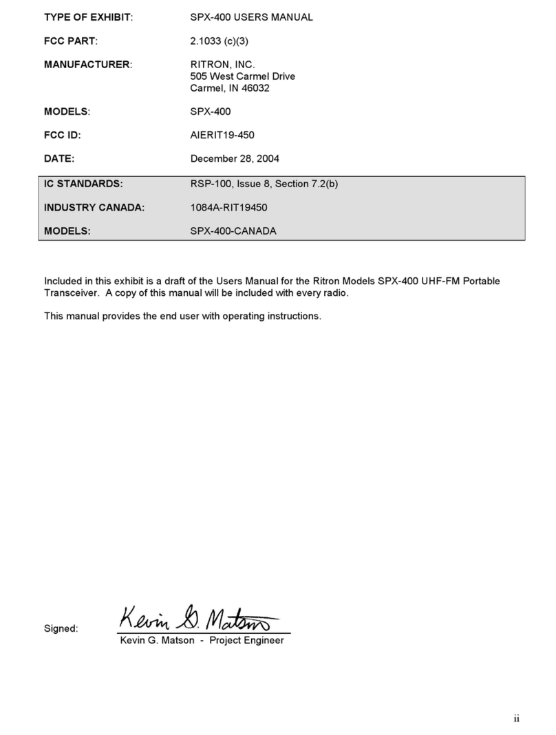
TYPE OF EXHIBIT: OPERATIONAL DESCRIPTION
FCC PART: 2.1033 (c)(6)
MANUFACTURER: RITRON, INC.
505 West Carmel Drive
Carmel, IN 46032
MODELS: SPX-200
FCC ID: AIERIT19-150
DATE: December 28, 2004
IC STANDARDS: RSP-100, Issue 8, Section 7.2(b)
INDUSTRY CANADA: 1084A-RIT19150
MODELS: SPX-200-BC, SPX-200-CANADA
Included in this exhibit is a draft of the Maintenance and Operating Manual for the Ritron Model SPX-200
VHF-FM Portable Transceiver.
Specifically, the manual includes a technical description of the SPX-200 sufficient to establish compliance
with the technical standards of the applicable rule part(s).
This includes, but is not limited to, the following items required under FCC Part 2.1033(c):
(1) FCC Identifier.
(2) A copy of the installation and operating instructions.
(3) Type of emission.
(4) Frequency range.
(5) Range of operating power, and means to provide variation in operating power.
(6) Maximum power rating.
(7) Tune-up procedure.
(8) A description of all frequency determining and stabilization circuits. A description of the circuits
used to suppress spurious radiation, limiting modulation, and limiting power.
(9) Drawing with labels for controls and complete circuit diagrams.
Signed: ________________________________
Kevin G. Matson - Project Engineer

58
SPX-200
(Preliminary)
MAINTENANCE / REPAIR / OPERATING
MANUAL

59
TABLE OF CONTENTS
CONTENTS ............................................................................................................................................................................... 1
1. INTRODUCTION............................................................................................................................................................... 60
2. OPRATION FEATURES ................................................................................................................................................. 3
3. TECHNICAL SPECIFICATIONS .................................................................................................................................. 61
1) GENERAL ..........................................................................................................................................................................4
2) TRANSMITTER.................................................................................................................................................................4
3) RECEIVER .........................................................................................................................................................................4
4. CIRCUIT DESCRIPTION .................................................................................................................................................. 5
1) PHASE-LOCK LOOP (PLL) CIRCUIT.......................................................................................................................... 5
2) TRANSMITTER ................................................................................................................................................................5
3) RECEIVER .......................................................................................................................................................................62
5. ALIGNMENT PROCEDURE ............................................................................................................................................ 6
1) MEASUREMENT CONDITION .....................................................................................................................................6
2) DISASSEMBLING THE UNIT......................................................................................................................................63
3) TRANSMITTER CIRCUIT ADJUSTMENT..................................................................................................................7
4) RECEIVER CIRCUIT ADJUSTMENT.........................................................................................................................64

60
1. INTRODUCTION
This manual is intended for use by experienced technicians familiar with similar types of commercial grade
communications equipment. SPX-200 is a micro size FM transceiver operating between 136 ~ 174 MHz. With the output
power of 5 W(1 ~ 5 W).
In addition to its small size, the SPX Series offers many advanced features that could only be found in the most expensive
Land Mobile Radios.
2. OPERATION FEATURES
2-1) Physical Layout
2-2) Panel controls
Power switch / Volume Control
Turn clockwise to switch ON the transceiver. Rotate to adjust the volume. To switch OFF the transceiver, turn
counterclockwise fully.
Emergency button
Pressing this key to enter the emergency mode
Antenna connector
Connect the supplied antenna here (SMA connector)
TX / RX / Battery Indicator (LED 3 colors)
On Transmitting
Red Blinking Low battery
On Receiving, monitoring
Green Blinking Different sub-tone when receiving
Orange On Initializing, programming and cloning

61
Function button (Menu / Esc.)
Universal connector
Connect the external accessories (speaker / microphone, cloning cable & wall charger) (optional)
Belt clip
MIC.
PTT(Push To Talk) Button
Hold down to transmit, release to receive.
Channel Select Button (Up & Down buttons)
Select the desired channel with pressing Up and Down button, pressing and holding down more than 1 second
Monitor Button
Press to monitor. Holding down over 2 seconds keeps monitoring function on, and press shortly again or PTT
Button to stop.
Lamp
This key illuminates the LCD and keys on the front panel.
Programmable keys
3. TECHNICAL SPECIFICATIONS
1) GENERAL
1) Frequency Range : 136 ~ 156 MHz / 146 ~ 174 MHz
2) Modulation Type : 11K0F3E / 16K0F3E (FM)
3) Channel capacity : 128 channels
4) Channel spacing : 12.5 kHz / 25kHz
5) Power Supply : DC 7.5V, Ni-Mh Rechargeable Pack
6) Current Drain : High Transmitter (5W) ----- 2000mA
Receiver (0.5W) ---------------350mA
Standby----------------------------45mA
Standby (PSC mode)------------40mA
7) Battery Life : 10hrs (Ni-Mh Rechargeable Pack)
(At 5%-5%-90% transmit-receive-standby cycles)
8) Operating Temperature : -30to +50
9) Dimension : 110(H) x 50.5(W) x 37.5(D) mm
10) Weight (W/Batteries) : 320g (1350mAH Rechargeable battery)
2) TRANSMITTER
1) Power Output : High (5W), Low (1W)
2) Frequency Stability : Better than +/- 0.0005% within operating temperature
3) Hum & Noise : -45dB (with 300Hz to 3KHz audio filter)
4) Spurious Emissions : Less than -65dBc
5) Audio Distortion : Less than 5% (1KHz tone 60% modulation)
6) Audio Response @6dB/oct : +1 to -3dB
7) Max deviation : ±2.5kHz at 12.5kHz / +/-5.0kHz at 25kHz
3) RECEIVER
1) Sensitivity (12dB SINAD) : Less than 0.25 uV(-119dBm)
2) Selectivity : -70dB
3) Hum & Noise : -45dB
4) Inter-modulation : -65dB
5) Spurious and image rejection : 70dBc
6) Maximum Audio Output(16Ω) : More than 500mW
7) Audio Distortion : less than 5% at 1kHz deviation

62
4. CIRCUIT DESCRIPTIONS
1) PHASE-LOCK LOOP (PLL) CIRCUIT
* REFERENCE OSCILLATOR
The reference oscillator consists of X401 in U401 with a frequency of 12.8MHz. The reference oscillator
frequency is stabilized by the thermistor R403 and drives a divider to produce a comparison frequency.
This comparison frequency is selected by decoding the first three bits of the data input from microcomputer.
* PROGRAMMABLE DIVIDER
The programmable divider in U401 consists of a two-modulus prescaler with a 7bit control register followed by a
11-bit internal programmable divider. The overall division ratio is selected by a single 19-bit world located on the
serial data bus.
* PHASE COMPARATOR
A digital-type phase comparator in U401 with output (pin 6) and an open drain lock detect output (pin 10)
compares divided VCO frequency with the comparison frequency.
* VCO CIRCUIT
The transmit/receive frequency is directly generated by the Colpitts oscillation circuit contains
Q402, Q405. The oscillation frequency is variable by applying the VCO control voltage to variable
to variable capacitors D401, D402, D403, D404 and D405, 406, 407, 408.
2) TRANSMITTER
* MIC AMP CIRCUIT
Voice signal from the microphone are applied to microphone amplifier U8 through MK2.
U8 contains a low-pass filter that has a 6dB/oct response between 300Hz and 3 kHz and eliminates hamonics
above 3 kHz. The Pre-emphasized audio signal is applied U8 pin 22 to adjust maximum frequency deviation by
software.
* VCO AND AMPLIFIER
The VCO signal output is amplified by Q101 and then fed to power module U405.
* POWER AMPLIFIER CIRCUIT
U405 is provided approximately 7.5V DC power source.
RF power output is adjusted by software (DA-TX power) to 1W~5W.
Signals from U405 is supplied through antenna switch D101 to a low-pass filter made up of L101, L102, L103 and
C101-C106, then applied to Antenna Jack.
3) RECEIVER
* ANT SWITCHING CIRCUIT
Signals from antenna connector fed to the antenna switching circuit through the low pass filter consisting of
L101~106. In receive mode, D101 is turned off, isolates the antenna from the transmitter circuit and matching
circuitry, so that the incoming signals are fed to the RF amplifier through L105.
* RF AMPIFIER CIRCUIT
The signals from the switching circuit are fed to the RF amplifier Q201 through a band pass filter made up of
spring coil, vvc diode and capacitor.
* FIRST MIXER CIRCUIT
The amplified signals are fed to Gate 1 of the first mixer Q202 through C230. First local oscillator signal is
supplied to Gate 2 of Q202 form the PLL circuit through C258 to convert the RF signals into 21.4MHz first IF
signal.
* IF CIRCUIT
The first IF signals from Q202 are fed to the matched pair crystal filter XFL201, then IF signals are amplified in
Q203. And those signals are fed to U201, which is composed of the second local oscillator, second mixer, limiter

63
amplifier, quadrature detector and active filter circuit. The second local oscillator at 20.945MHz with X202 and is
fed to the second mixer with the first IF signals to convert into 455kHz second IF signals..
The second IF signals leave through pin 3,and are fed to external ceramic filters XFL203, XFL204 which has
excellent selectivity, then fed to U201 (pin 5) again to be amplified and detected. Narrow /Wide band are switched
by software. The detected AF signals are output from pin 9.
* AUDIO AND SQUELCH CIRCUIT
The detected audio signals are put through a 6dB/oct de-emphasis circuit made up of R221 and C248. The signal
is then applied to audio power amplifier U3 through the volume control VR1 to obtain enough power to driver the
speaker.
Part of the recovered noise signal is fed to the integrated operational amplifier inside U201, which, with R232,
C256, C257 makes up an low pass filter . The DC signal detected by U201 (pin13) reaches the integrated DC
amplifier in U201 which has hysteresis to prevent jitter. The sensitivity of squelch is adjusted by VR201.
5. ALIGNMENT PROCEDURE
1) MEASUREMENT CONDITION
The following sections describes the alignment procedure for SPX-200 VHF transceiver under the following reference
environment conditions:
Temperature : 25C (77F)
Relative Humidity : 65%
Power Supply Voltage : 7.5VDC +/- 5%
TEST EQUIPMENT / TOOLS REQUIRED
The following list of equipment is recommended for use in setting up the radio properly. Please ensure the test equipment
are calibrated according to the manufacturer’s instructions:
-Frequency counter more than 100MHz +/-100Hz tolerance, high input impedance and high sensitivity
-FM Signal generator, 1GHz with adjustable frequency, FM deviation, and RF output attenuators. 50ΩOutput
impedance.
-Oscilloscope, high input impedence.
-16Ω1 Watt resistor as loudspeaker load
-Audio Signal Generator, 10Hz to 20KHz, 600Ωimpedance with attenuators.
-RF Watt meter, with 50Ω10 Watt termination resistor (Or RF Voltmeter with 50Ωtermination and external 50Ω
attenuators)
-Regulated Power Supply 7.5VDC 3A output
-Digital A-V-O Multi-meter
-SINAD Meter
-External Speaker Mic. plug (or special audio test jig)
-Interconnection test cable for RF and Control PCB
-Circuit Diagram for SPX-200
-PCB layout diagram for SPX-200
-Tuning tools for RF/IF transformer and the VR potentiometers
2) DISASSEMBLING THE UNIT
The antenna
Disconnect the antenna
The Cover
-Remove the battery.
-Remove the 2 screws.
-The case could then be opened for servicing.
-Be careful NOT to disconnect the pin connector between RF board and Control board.

64
The PCBs
-The radio consists of two PCBs, the RF (rear side) and control board (front side)..
-On the RF Board, connect ANT1 to a signal generator or RF power meter.
-On the RF Board, connect Power Supply to the battery terminal contacts.
-Connect External Speaker Mic Plug (or Audio Test Jig) to J3.
3) TRANSMITTER CIRCUIT ADJUSTMENT
-Crystal frequency
On receiving mode, check Crystal output is at 12.8MHz
-Transmitter Frequency
Connect RF Power meter to ANT1, Activate PTT to transmit on 146.125MHz.
-Transmitter Output Power
Activate PTT to transmit on 146.125MHz, Output power is adjustable by software
-Transmitter Sub-Audible Tone Deviation
Set radio to transmit on M146.125Hz, with CTCSS code 01 (67Hz) and no audio modulation. It is adjustable by
software for 0.45KHz deviation.
-Transmitter Deviation Limit
Set radio to transmit on 146.125MHz, with CTCSS code 01 (67Hz) and audio modulation. At the external
microphone input, inject 1KHz tone at –20dBm. It is adjustable by software for 2.3KHz deviation.
4) RECEIVER CIRCUIT ADJUSTMENT
-FM Demodulator Adjustment
Set radio to receive on 146.125MHz, No CTCSS or DCS. Connect RF Signal Generator to ANT1, Set generator to
146.125MHz at –60dBm (50Ω) output with 1KHz tone modulation at 1.5KHz deviation.
-Receiver Squelch Adjustment
After checking the receiver sensitivity, further lower the RF Signal Generator output to 8-10dB SINAD and observe
the squelch circuit operates. Adjust VR201 if necessary.
Other manuals for SPX-200
1
Table of contents
Other Ritron Transceiver manuals

Ritron
Ritron DTX- 60 Series User manual

Ritron
Ritron Q Series User manual

Ritron
Ritron XT Series User manual
Ritron
Ritron DTXM-NXDN Series Operating and maintenance manual

Ritron
Ritron RPM-050 User manual

Ritron
Ritron DTXM-465-0BN6I-M User manual
Ritron
Ritron DTX Plus Series User manual
Ritron
Ritron DTX-165-0 Operating and maintenance manual

Ritron
Ritron SST-444 Quick start guide

Ritron
Ritron RT-453 Operating and maintenance manual

