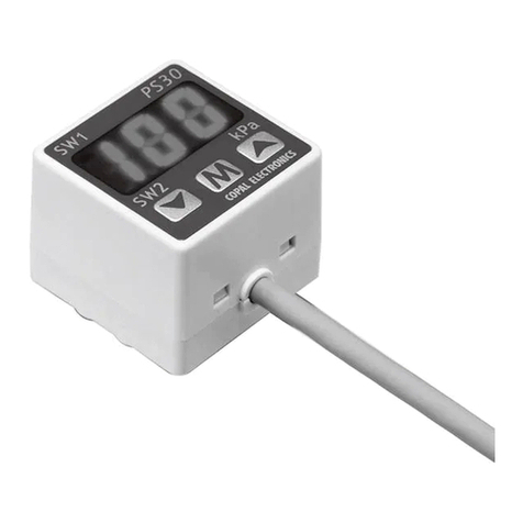
Copal PS60 User manual

Thankyouforpurchasinga
NIDECCOPALELECTRONICSCORP.product.
Forproperandoptimaluseoftheproduct,pleasereadthis
manualthoroughlybeforeusing.
Keepthismanualforfuturereference.
DISPLAY TYPE
CONPOUND PRESSURE SWITCH
INSTRUCTION MANUALVer.2.1
ImportantInformationandWarnings
①Non-corrosivegasesshouldbeusedaspressuremediaforPS60.
②ThemaximumapplicablepressureforthePS60-102R/302Ratthetimeofvacuumbreakis500kPa.
③Alwayscarryoutwiringworkwiththepoweroff.
④Pressthe buttonmorethan3secondsintheOperationMode,thepanellockfunctionwillbecompletedanddisabletothe
keyoperation.PleaserefertothefollowingPanellockfunctionandcancelthepanelockfunction.
⑤Forstability,usearegulateddirectcurrentpowersupply.
Surgeabsorbingdevices(diodes,varistors,etc.)arenecessaryifinductiveloadssuchasrelaysandsolenoidsareconnectedto
thesamepowerlineasthePS60.Donotwireinparalleltohighvoltagecablesorpowerlines,orusethesamecableducts
whichcontainhighvoltagecablesorpowerlines.
⑥Checkfluctuationsinpowervoltagesothatthepowerinputcannotexceedtherating.Alsopleasedonotgivearapidvoltage
fluctuation like intercepting the eenergization immediately after starting and during setting operation. Memory data may
disappear,andwhitchresultsinadefectofoperation/
⑦Becarefulnottoapplyforcetothedisplayareaofthemainbodyduringpiping.
⑧UsepHneutraldetergentstocleanthebody.Donotuselacquerthinnerandothersolventsforcleaning.
⑨Donotusepointedobjectssuchaspenstopressthesettingbuttonsonthedisplaypanel.Doingsomaydamagethesetting
buttonsbypiercingthem.
⑩Donotputapieceofwireorotherlongthinobjectfrompressureport.Doingsomaydamagetheinternaldiaphragmtocause
malfunctioning.
⑪Do not use the product in a place where much steams
and/or dust exist or the product may be subjected to
directwateroroilsplash.
⑫【Recommendedmeasuresagainstnoiseinterference】
It is recommended to use noise absorbing components
(line filter, surge absorber, etc.) in the power supply
terminalofthePS60.
Powersupplyunit
DCoutputACinput
FG
+V
EarthingofFGterminal
Surgeabsorbingcircuit
PS60
Nishi-ShinjukuKimurayaBidg.,7-5-25
Nishi-ShinjukuShinjuku-kuTokyo160-0023,JapanPhone.:(03)3364-7055
Formoredetailedinformationpleaseaskforthenearestdistributororthefollowingsalescenter.
(CompliancewithEMCStandards)
marking
PS60

COM
(biue)
(White)SwitchOutput2
(black)Switch
Output1
(brown)
LED
4
3
1
2
Load Load
Display
LED×2
Sensor
Maincircuit
Powersupply
DC10.8〜26.4V
(White)SwitchOutput(White)SwitchOutput22(White)SwitchOutput2
Load
(brown)
(black)SwitchOutput1
COM
3
LED×2
4
1
2
Load
LED
(biue)
Display
Sensor
Maincircuit
Powersupply
DC10.8〜26.4V
PS60
P2LED
(SW2)LED
P1LED
DOWNbutton
UPbutton
3digitsLED
MODEbutton
Displayunit
(SW1)LED
1
Specifications
Type(Pressurereference)
Ratedpressurerange
Maximumpressure
Break-downpressure
Acceptablemedia
Powersupply
Currentconsumption
Switchoutputs
Pressureindication
Switchstatusindication
Operatingconditions
Thermalerror
Pressureport
Pressurereceivingareamaterial
Netweight
Accessories
Model PS60
103R
OutputElectricalDiagram(WirecolorscorrespondtoI.E.Cstandards)
Ditailsofthefrontpanel
-0.10〜1.00MPa
1.5MPa
2.0MPa
302R
-100〜300kPa
600kPa
1.0MPa
102R
-100〜100kPa
200kPa
500kPa
Hysteresis
Repeatability
Response
Shortcircuitprotection
Accuracy
IPprotection
Operatingtemperature
Operatinghumidity
Vibrationresistance
Shockresistance
EMC
NPN(Twooutputstype) PNP(Twooutputtype)
Gaugepressure
Non-corrosivegases
12V〜24VDC±10%,rippleP-P10%orless
30mAmaximum
NPN(Twooutputs),PNP(Twooutputs)Transistor,opencollector
Switchrating:30VDC,100mAmaximum
Residualvoltage:1.2Vmaximum(NPN)/2.2Vmaximum(PNP)at100mA
0〜30countsetting(adjustable)
±0.3%FS
5msmaximum
Included
Signed3digits,7-segment-LEDindication(samplingcycle:approx.4timespersecond)
±1%FS±1digit
Output1(P1)andoutput2(P2),LED(red)lightupwhenswitchoutputsareON.
MeetsIP40ofIEC
−10〜50℃(storage−20〜70℃)
35〜85%RH
10〜500Hz,amplitude1.5mm/98.1m
/
S2,threedirections,twohourseach
490m
/
S2,threedirections,threetimeseach
EMI:EN55011Group1,ClassB:1998
±3%FS(0〜50℃,referencetemp.25℃)
M5femalescreew
Singlecrystalsilicon
Approx.50g(included1.5mcable)
Connectorwithcable(1.5m),DINrailadapter
EMS:EN61326-1:1997/A-1:1998/Thepermissiblevariationsindisplay
countsandsetvalueofswitchoutputnotexceed±5%FS.
P1
P2
kPa

PS60 PS60
PS60
Functions
●Youcanselectswitchworkingmodefromtheoptionsshowninthetablebelow.
(Note1)IntheSeparateMode,SW1andSW2workseparately.
(Note2)IntheWindowComparatorMode,theminimumvalueforSW1andSW2correspondstoSetting1andthemaximumvaluetoSetting2.
※Forhowtosettheswitchoutput,seethedescriptionoftheinitialsettingmode.
Switchworkingmode
●Whenyoudonotoperateanybuttonsforabout10seconds,thesystemwillautomaticallyselectnon-displaymodeandtheLEDindicatorsectionwillgooff.
PressinganykeywillcausetheLEDindicatorsectiontocomeonbackagain.
(Note1)Thedecimalpointshowninthefigureontherightblinksduringnon-displaymode.
(Note2)SwitchoutputsandswitchLEDsareoperableevenduringnon-displaymode.
(Note3)Errormessageswillappearduringnon-displaymode.
※Forhowtoselectnon-displaymode,seethedescriptionoftheinitialsettingmode.
Non-displaymode(Lowpowermode)
●Youcanselectaconversionfactorfromtheoptionsshowninthetableontheright.
(Note1)Slashedbox:Nofactorsoptionsareavailableduetoinappropriateresolution
andthenumberofdigitsfordisplay.
※Forhowtosettheconversionfactor,seethedescriptionoftheinitialsettingmode.
Conversionfactor
●Twodifferentdigitalfilters(25msand250ms)areavailable.
Thedigitalfiltersareusefulwhenitishardtotakereadingsduetotoogreatfluctuationsinpressure.
(Note1)Anyselecteddigitalfilterwillbereflectedonthepressuredisplayandswitchaction.
※Forhowtosetthedigitalfilter,seethedescriptionofthepressuresettingmode.
Digitalfilter
AllLEDflashonce. TheOperationsMode(pressule
detection)isactivated.
InitialLEDDisplay
ErrorMessages
■Ifthefollowingerrormessagesaredisplayed,followtheproceduresinthetable:
2
Errormessage
Problem Solution
Overloadcurrent.(BrinkingofSW1orSW2indicates
excessivecurrentonSW1orSW2.)
Pressuredetectedwhenadjustingthezeropoint.
Appliedpressureishigherthanthemaximumvalue
ofthepressuredisplayrange. Checktheappliedpressure.
Pressthe buttonandresetthe display.Releasetheappliedpressure
inthepressureport(openedtotheatmosphere)andadjustthezeropointagain.
Disconnectthepower,thenchecktheloadcondition.
Therearefouroperationmodes.Thereareshowninthediagramsbelow.
SeparateMode
P1:Setting1,P2:Setting2,H:Hysteresis
WindowComparatorMode
(HIoperation)
OFF
ON
-Pr Pr
HH
P1:SW1 P2:SW2
ON
OFF
-Pr Pr
HH
P1:SW1 P2:SW2
(LOoperation)
(Aoperation)
OFF
ON ON
-Pr Pr
HH
P1 P2
P1 P2
(Boperation)
OFF OFF
ON
-Pr Pr
HH
P1≦P2 or P1≧P2 P1≦P2−2H
Mode
Operation
Numberselected
SW1
Separate
H
○
○
L
○
○
A
○
○
B
○
○
H
○
○
L
○
○
A
○
○
B
○
○
WindowComparator
Setting1
Minimum:Setting1
Maximum:Setting2
Minimum:Setting1
Maximum:Setting2
Setting2
Separate
WindowComparator
SW2Output
Number
selected
Pressurerange
103R302R102R
─
−
0.10〜1.00
─
−
1.0〜10.0
−
14〜145
─
−
100〜300
─
−
75〜225
−
1.00〜3.00
−
14.5〜43.5
29.5〜0.0
(-symboldoesnotdisplay)
−
100〜100
─
−
75〜75
−
1.00〜1.00
−
14.5〜14.5
29.5〜0.0
(-symboldoesnotdisplay)
(
k
Pa)
(MPa)
P1
P2
kPa
P1
P2
kPa
P1
P2
kPa

PS60
PS60
3
Makinginitialsetting
EnteringInitialSettingMode
OperationalProcedures
InitialSettingMode
Thismodeisusedtosetnon-displaymode,magnificationandswitchoutputs.
Non-displaysetting(twoselections)
Factorsetting(fiveselections)
Switchworkingmodesetting(eightcombinations)
P1setting
P2setting
Hysteresis(0〜30counts)
Filtersetting(F0〜F2)
Pressthe and buttonssimultaneously.
Pressthe buttonmorethanonesecond.
Pressthe and buttonssimultaneously.
Pressthe buttonmorethanonesecond.
Displaymode
:
StandardMode
:Non-display
Mode
Factor
102R/302R
Switchworkingmode
:SeparateMode
103R :WindowComparatorMode
Operations
Mode
Initial
Setting
Mode
Pressure
Setting
Mode
Pressthe and buttonssimultaneouslyinOperationsMode.
AfterswitchedtoInitialSettingMode,thethirddigitwillblink.
(Thevalues forthe102R/302Rmodeland forthe103Rhavebeensetinthefactory.)
Pressthe buttontomovetothenextdigit.ThevalueofthedigitmaybesetwhentheLEDbelow
thedigitblinks.
Thenumberwillchangeeverytimethe or buttonispressed.
Pressthe buttontomovetothenextdigit.
P1
P2
kPa
P1
P2
kPa

PS60
PS60
PS60
PS60
PS60
P1
P2
kPa
P1
P2
kPa
P1
P2
kPa
P1
P2
kPa
P1
P2
kPa
PS60
P1
P2
kPa
Zero-pointadjustment
Settingpressurevalue
EnteringPressureSettingMode
4
PressureSettingMode
ThismodeisusedtomakeSetting1,Setting2,hysteresisanddigitalfiltersetting.
ZeroPointAdjustment
Setting1(P1)
Setting2(P2)
Hysteresis(H)setting
Digitalfiltersetting
Zero-pointadjustmentiscompletedwhen
lightgoesout.
Zero-pointadjustmentvalueisnoterased
evenifthepowersupplyisturnedoff.
Adjustthepressureindicationatthetimeofpressurereleaseinthepressureportto"zero".
Pressthe and buttonssimultaneouslyinOperationsMode.
AfterswitchedtoPressureSettingMode,P1LEDshouldbe
blinkingtoindicatethevalueforSetting1.
Adjustrthepressureindicationtozerowhenthepressureportisreleased.
・Openthepressureporttotheatmosphericpressurefirst.
・Press and buttonssimultaneouslyintheOperationmode.
・Whenfingerisreleasedfromeachbutton, blinkstwice.
TheP1LEDshouldbeblinking.
Usethe or buttontoselectavalueforSetting1(P1).
(Thevalues for102Rand for103Rhavebeensetinthefactory.)
(Note1)Thesettingcanonlybemadewithintheallowabledisplayrange.
(Note2)ThesettingshouldmeetP1≦P2-2HwhenWindowComparatorModeisselected.
TheP2LEDshouldbeblinking.
Usethe or buttontoselectavalueforSetting2(P2).
(Thevalues for102Rand for103Rhavebeensetinthefactory.)
(Note1)Thesettingcanonlybemadewithintheallowabledisplayrange.
(Note2)ThesettingshouldmeetP1≦P2-2HwhenWindowComparatorModeisselected.
TheP1andP2LEDsshouldbeblinking.
Usethe or buttontosetthehysteresis(H).
(Thevalues for102R/302Rand for103Rhavebeensetinthefactory.)
(Note1)Thesettingshouldbe30countsorless.
(Note2)ThesettingshouldmeetP1≦P2
-
2HwhenWindowComparatorModeisselected.
Usethe or buttontosetthedigitalfilter.
:Nofilter, :25msfilter, :250msfilter
(Thevalue hasbeensetinthefactory.)

35±0.3
HookonandPushdown
PushinandPulloff
(26.5)
(24)
PS60
P1
P2
kPa
DINrailattachment
5
Piping
PipingandInstallation
Whenconnectingaavailablejointtothepressureport,holdthebasesectionofthemainbodyandmakesurethatthetighteningtorqueis1.0N・m(M5female)or
less.
Note)Pleasedonotdirectlyholdthecaseonlywhentightening.Also,donotusethewrenchtoanyotherpartthantheportsectionwhentightening.Suchhandling
maycauseabreakageoftheswitch.
DINrailadapter(accessory)
Note:ThisDINrailadaptercannotbeunfixedonceattached.
Stopper(POM)
Bass(PBT)
Panellockfunction
PanelProtection
Panellockfunctionisnoterasedevenif
thepowersupplyisturnedoff.
Thepanellockfunctionisusedtolockthekeyoperationinordertopreventpresetvaluesfrombeing
accidentallychanged.
・Toenablethepanellockfunction,press buttonmorethan3seconds.
blinkstwiceandthebuttonsarelocked.
・Todisablethepanellockfunction,press buttonmorethan3seconds.
blinkstwiceandthebuttonsarelocked.
PS60-103R-NMCN
RANGE:-0.10〜1.00MPa
WHITE:SWITCH2(NPN30V100mAmax)
BLUE:COMMON
BROWN:POWERSUPPLY(DC12〜24V)
BLACK:SWITCH1(NPN30V100mAmax)
LOT.8M1
PS60-103R-NMCN
RANGE:-0.10〜1.00MPa
WHITE:SWITCH2(NPN30V100mAmax)
BLUE:COMMON
BROWN:POWERSUPPLY(DC12〜24V)
BLACK:SWITCH1(NPN30V100mAmax)
LOT.8M1
PS60-103R-NMCN
RANGE:-0.10〜1.00MPa
WHITE:SWITCH2(NPN30V100mAmax)
BLUE:COMMON
BROWN:POWERSUPPLY(DC12〜24V)
BLACK:SWITCH1(NPN30V100mAmax)
LOT.
8M
1
MADE IN
JAPAN
MADE IN
JAPAN
MADE IN
JAPAN

PS60
6
ModelNumbers
Warranty
PS60−102R−NMCN
OutlineDimensions(Unit:mm)
MADE IN
JAPAN
Table of contents
Other Copal Switch manuals
Popular Switch manuals by other brands

HP
HP 316095-B21 - StorageWorks Edge Switch 2/24 Service manual

Siemens
Siemens SCALANCE X320-3LD FE operating instructions

D-Link
D-Link xStack DGS-3426 user manual

Ikegami
Ikegami VS-4L operating instructions

Huawei
Huawei Enterprise S2700 Series quick start

Dell
Dell PowerConnect M6220 Getting started guide