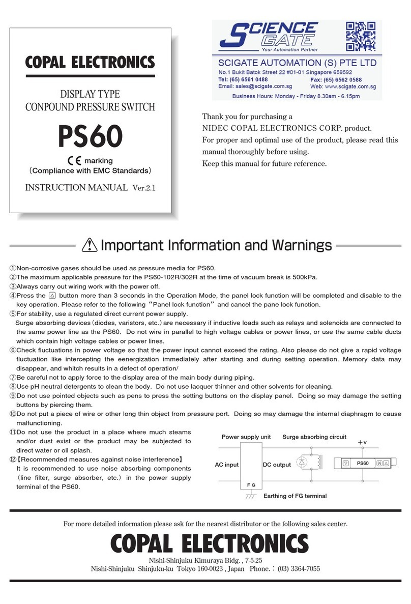
Copal PS30 User manual

1
INSTRUCTION MANUALVer.2.1a
Nishi-ShinjukuKimurayaBldg.,7-5-25
Nishi-Shinjuku, Shinjuku-ku,Tokyo160-0023Japan Phone:(03)3364-7055
Formoredetailedinformationpleaseaskforthenearest
distributororthefollowingsalescenter.
Thankyouforpurchasinga
NIDECCOPALELECTRONICSCORP.product.
Forproperandoptimaluseoftheproduct,pleaseread
thismanualthoroughlybeforeusing.
Keepthismanualforfuturereference.
DISPLAYTYPEPRESSURESWITCH
PS30
ImportantInformationandWarnings
①Non-corrosivegasesshouldbeusedaspressuremediaforPS30.
②ThemaximumapplicablepressureforthePS30-102Ratthetimeofvacuumbreakis500kPa.
③Alwayscarryoutwiringworkwiththepoweroff.
④Forstability,usearegulateddirectcurrentpowersupply.
Surgeabsorbingdevices(diodes,varistors,etc.)arenecessaryifinductiveloadssuchasrelaysandsolenoidsareconnectedtothesame
powerlineasthePS30. Donotwirein paralleltohighvoltagecables orpowerlines,oruse thesamecableductswhich containhigh
voltagecablesorpowerlines.
⑤Checkfluctuationsinpowervoltagesothatthepowerinputcannotexceedtherating.
⑥Becarefulnottoapplyforcetoanywiresduringhandling,orapplyforcetothedisplayareaofthemain
bodyduringpiping.
⑦UsepHneutraldetergentstocleanthebody.Donotuselacquerthinnerandothersolventsforcleaning.
⑧Donotusepointedobjectssuchaspenstopressthesettingbuttonsonthedisplaypanel.Doingsomay
damagethesettingbuttonsbypiercingthem.
⑨Do not put a piece of wire or other long thin object from pressure port. Doing so may damage the
internaldiaphragmtocausemalfunctioning.
⑩Donotusetheproductinaplacewheremuchsteamsand/ordustexistortheproductmaybesubjected
todirectwateroroilsplash.
⑪[Recommendedmeasuresagainstnoiseinterference]
Itisrecommendedtousenoiseabsorbingcomponents(linefilter,surgeabsorber,etc.)inthepowersupply
terminalofthePS30.
marking
(CompliancewithEMCStandards)
Surgeabsorbingcircuit

2
Specifications
OutputElectricalDiagram(WirecolorscorrespondtoI.E.Cstandards)
Detailsofthefrontpanel
Type(Pressurereference)
Ratedpressurerange
Maximumpressure
Break-downpressure
Acceptablemedia
Powersupply
Currentconsumption
Switchoutputs
Pressureindication
Switchstatusindication
Operatingconditions
Thermalerror
Pressureport
Pressurereceivingareamaterial
Netweight
Gaugepressure
Non-corrosivegases
12V〜24VDC±10%,rippleP-P10%orless
40mAmaximum
Twooutputs:NPN/PNPTransistor,opencollector
Switchrating:30VDC,100mAmaximum
Residualvoltage:1.2Vmaximum(NPN)/2.2Vmaximum(PNP)at100mA
0〜30countsetting(adjustable)
±0.3%F.S.
5msmaximum
Included
Signed21/2digit,7-segment-LEDindication(samplingcycle:approx.4timespersecond)
±1%FS±1digit
Output1(SW1)andoutput2(SW2),LED(red)lightupwhenswitchoutputsareON.
MeetsIP40ofIEC
−10〜50℃(storage−20〜70℃)
35〜85%RH
10〜500Hz,amplitude1.5mm/98.1m/S
2
,threedirections,twohourseach
490m/S
2
,threedirections,threetimeseach
EMI:EN550111998classB(Group1)
±3%FS(0〜50℃,referencetemp.25℃)
M5femalescrew,O-ringgroove(P8)
Singlecrystalsilicon
Approx.60g(included1.5mcable)
Hysteresis
Repeatability
Response
Shortcircuitprotection
Accuracy
IPprotection
Operatingtemperature
Operatinghumidity
Vibrationresistance
Shockresistance
EMC
Model PS30
102R 103R
−100〜100kPa
200kPa
500kPa
−0.1〜1.0MPa
1.5MPa
2.0MPa
EMS:EN61326-1:1997/A-1:1998/Thepermissiblevariationsindisplay
countsandsetvalueofswitchoutputnotexceed±5%FS.
NPNOpenCollectorOutputModel PNPOpenCollectorOutputModel
(brown)
(black)
Switchoutput1(black)Switchoutput1
(white)Switchoutput2
(blue)
Powersupply:
12〜24VDC
COM
Load Load
Maincircuit
Display
LED
Sensor
(brown)
(black)
Switchoutput1
(white)Switchoutput2
(blue)
Powersupply:
12〜24VDC
COM
Load Load
Maincircuit
Display
LED
Sensor
PS30SW1
kPaSW2
SW1LED(red) 21/2digitLEDdisplay
Unit
Upbutton
Modebutton
SW2LED(red)
NegativepressureLED
(red)
Downbutton
Wirecolor
Brown
Blue
Black
White
Connection
Power⊕
Common
SWOutput1
SWOutput2

Functions
3
ErrorMessages
●Youcanselectswitchworkingmodefromtheoptionsshowninthetablebelow.
(Note1)IntheSeparateMode,SW1andSW2workseparately.
(Note2)IntheWindowComparatorMode,theminimumvalueforSW1andSW2correspondstoSetting1andthemaximumvaluetoSetting2.
※Forhowtosettheswitchoutput,seethedescriptionoftheinitialsettingmode.
●Whenyoudonotoperateanybuttonsforabout10seconds,thesystemwillautomaticallyselectnon-displaymode
andtheLEDindicatorsectionwillgooff.PressinganykeywillcausetheLEDindicatorsectiontocomeonbackagain.
(Note1)Thedecimalpointshowninthefigureontherightblinksduringnon-displaymode.
(Note2)SwitchoutputsandswitchLEDsareoperableevenduringnon-displaymode.
(Note3)Noerrormessageswillappearduringnon-displaymode.
※Forhowtoselectnon-displaymode,seethedescriptionoftheinitialsettingmode.
●Twodifferentdigitalfilters(25msand250ms)areavailable.
Thedigitalfiltersareusefulwhenitishardtotakereadingsduetotoogreatfluctuationsinpressure.
(Note1)Anyselecteddigitalfilterwillbereflectedonthepressuredisplayandswitchaction.
※Forhowtosetthedigitalfilter,seethedescriptionofthepressuresettingmode.
■Ifthefollowingerrormessagesaredisplayed,followtheproceduresinthetable:
Switchworkingmode
Digitalfilter
Conversionfactor
Non-displaymode
(Note1)Noerrormessageswillbeshownwhennon-displaymodeisselected.
(Note2)Whentheappliedpressureexceeds110%ofratedpressure,thedisplayindicate“flashing”or“−L−”or“−H−”.
Thisdisplayedvalueisnotaccuratevalue,pleaseusewithintheratedpressurerange.
●Youcanselectaconversionfactorfromtheoptionsshowninthetableontheright.
(Note1)Slashedbox:Nofactorsoptionsareavailableduetoinappropriateresolution
andthenumberofdigitsfordisplay.
※Forhowtosettheconversionfactor,seethedescriptionoftheinitialsettingmode.
Errormessage
Problem Solution
Overloadcurrent.(BrinkingofSW1orSW2indicates
excessivecurrentonSW1orSW2.)
Appliedpressureishigherthanthemaximumvalue
ofthepressuredisplayrange.
Pressuredetectedwhenadjustingthezeropoint.
ExaminationbyNidecCopalElectronicsisrequired.
Pressurevalueexceeds110%oftherating.(Thiserrorexamples
whenthepressuremorethan111kpaisappliedtothe102Rmodele.)
Appliedpressureishigherthanthemaximumvalue
ofthepressuredisplayrange. Checktheappliedpressure.
Checktheappliedpressure.
Pressthe buttonandresetthe display.Releasetheappliedpressure
inthepressureport(openedtotheatmosphere)andadjustthezeropointagain.
TelephonethenearestofficeorSensorDepartmentofNidec
CopalElectronicsCorp.
Disconnectthepower,thenchecktheloadcondition.
M
PS30SW1
kPaSW2
Number
selected
Pressurerange
102R
Factor
×1
×0.75
×0.01
×0.145
Displayrange
-100〜100
-75〜75
-1.00〜1.00
-14.5〜14.5
Factor
×1
×10
×145
Displayrange
-0.10〜1.00
-1.0〜10.0
-14〜145
103R
Output
Mode
Operation
Numberselected
SW1
Separate
H
○
○
L
○
○
A
○
○
B
○
○
H
○
○
L
○
○
A
○
○
B
○
○
WindowComparator
Note1
Setting1
Note2
Minimum:Setting1
Maximum:Setting2
Minimum:Setting1
Maximum:Setting2
Note1
Setting2
Note2
Separate
WindowComparator
SW2
Therearefouroperationmodes.Thereareshowninthediagramsbelow.
SeparateMode
P1:Setting1,P2:Setting2,H:Hysteresis
WindowComparatorMode
(HIoperation)
OFF
ON
-Pr Pr
HH
P1:SW1 P2:SW2
ON
OFF
-Pr Pr
HH
P1:SW1 P2:SW2
(LOoperation)
(Aoperation)
OFF
ON ON
-Pr Pr
H H
P1 P2
P1 P2
(Boperation)
OFF OFF
ON
-Pr Pr
H H
P1≦P2 or P1≧P2 P1≦P2−2H

4
Makinginitialsetting
EnteringInitialSettingMode
ExitingInitialSettingMode
OperationalProcedures
InitialSettingMode
Thismodeisusedtosetnon-displaymode,magnificationandswitchoutputs.
Operations
Mode
Initial
Setting
Mode
Pressure
Setting
Mode
Non-displaysetting(twoselections)
Factorsetting(fiveselections)
Switchworkingmodesetting(eightcombinations)
SW1setting
SW2setting
Hysteresis(0〜30counts)
Filtersetting(F0〜F2)
M
Pressthe and buttonssimultaneously.
M
Pressthe buttonmorethanonesecond.
▼
M
Pressthe and buttonssimultaneously.
M
Pressthe buttonmorethanonesecond.
▲
M
Pressthe and buttonssimultaneouslyinOperationsMode.
AfterswitchedtoInitialSettingMode,thethirddigitwillblink.
(Thevalues forthe102Rmodeland forthe103Rhavebeensetinthefactory.)
▼
PS30SW1
kPaSW2
M
M
Pressthe buttontomovetothenextdigit.Thevalueofthedigit
maybesetwhentheLEDbelowthedigitblinks.
Thenumberwillchangeeverytimethe or buttonispressed.
▼
▼
▲
▲
▼
▲
▼
▲
Pressthe buttontomovetothenextdigit.
Displaymode
:
StandardMode
:Non-display
Mode
:× 1
:×0.75
:×0.01
:×0.145
Factor
102R
Switchworkingmode
:Separate
Mode
▼
▲
:× 1
:× 1 0
:×145
103R
:Window
Comparator
Mode
PS30SW1
kPaSW2
▲
▼▲
▼
▲
▼
▲
▼
▲
▼
▲
▼
▲
▼
▲
▼
▲
▼
▲
▼
▲
▼
▲
▼
▲
▼
M
Pressthe buttonmorethanonesecond.
TheinitialsettingswillbesetandyouwillreturntoOperationsMode.
PS30SW1
kPaSW2

EnteringPressureSettingMode
5
PressureSettingMode
ThismodeisusedtomakeSetting1,Setting2,hysteresisanddigitalfiltersetting.
Settingpressurevalue
ExitingPressureSettingMode
M
Pressthe and
buttonssimultaneouslyinOperationsMode.
AfterswitchedtoPressureSettingMode,SW1shouldbeblinkingtoindicatethevalueforSetting1.
(Thevalues for102Rand for103Rhavebeensetinthefactory.)
▲
PS30SW1
kPaSW2
M
Pressthe button.
M
Pressthe button.
M
Pressthe button.
M
Pressthe button.
TheSW1LEDshouldbeblinking.
Usethe or buttontoselectavalueforSetting1(P1).
(Thevalues for102Rand for103Rhavebeensetinthefactory.)
(Note1)
Thesettingcanonlybemadewithintheallowabledisplayrange.
(Note2)ThesettingshouldmeetP1≦P2−2HwhenWindowComparatorModeisselected.
▼ ▲
TheSW2LEDshouldbeblinking.
Usethe or buttontoselectavalueforSetting2(P2).
(Thevalues for102Rand for103Rhavebeensetinthefactory.)
(Note1)
Thesettingcanonlybemadewithintheallowabledisplayrange.
(Note2)ThesettingshouldmeetP1≦P2−2HwhenWindowComparatorModeisselected.
▼ ▲
TheSW1andSW2LEDsshouldbeblinking.
Usethe or buttontosetthehysteresis(H).
(Thevalues for102Rand for103Rhavebeensetinthefactory.)
(Note1)Thesettingshouldbe30digitsorless.
(Note2)ThesettingshouldmeetP1≦P2−2HwhenWindowComparatorModeisselected.
▼ ▲
Usethe or buttontosetthedigitalfilter.
:Nofilter, :25msfilter, :250msfilter
(Thevalue hasbeensetinthefactory.)
▼ ▲
Setting1(P1)
Setting2(P2)
Hysteresis(H)setting
Digitalfiltersetting
PS30SW1
kPaSW2
PS30SW1
kPaSW2
PS30SW1
kPaSW2
PS30SW1
kPaSW2
M
Pressthe buttonmorethanonesecond.
ThepressuresettingwillthentakeeffectandyouwillreturntoOperationsMode.
PS30SW1
kPaSW2

6
Adjustingzeropoint
Exitingzeropointadjustment
ZeroPointAdjustment
Adjustthepressureindicationatthetimeofpressurereleaseinthepressureportto"zero".
Piping
PipingandInstallation
Holdthebasesectionofthemainbodytoconnectacommerciallyavailablefitting(M5malescrew)tothemainbody.Tightenwithatorqueof1.0N・morless.
(Note)Donotapplyanyforceonthecoversectionofthemainbodyduringtightening.Theswitchunitmaybreak.
Backmountingscrews
Themainbodycanbesecuredtothepanelbyusingthemountingscrewholeslocatedontheback(2−M3,effectivedepth:6mm).Toinstall,holdtheuniton
thebasesectionwhentighteningthescrews.Useatighteningtorqueof0.3N・morless.
(Note)Donotapplyanyforceonthecoversectionofthemainbodyduringtightening.Theswitchunitmaybreak.
AngledBrackets(Option)
PortBlock(soldseparately)
If using the port block(sold separately), put the O-ring(P8)in the O-ring groove located on the
backofthemainbodyasshowninthefigurebelow,andinstalltheportblockbytwoM3×10male
screws.When installing, hold the basesection of themain body, then tighten themale screws.
Useatighteningtorqueof0.3N・morless.
Whenconnectafittingtotheportblock,windsealingtapearoundthepipetopreventairleakage.
Theother pressure portwhich are not to be used should bestopped up withthe sealing screw
provided. In this case, wind sealing tape around the screws before using. Any firstly tightenthescrewsusing
fingerstoavoiddamagetothescrewthreads.Finally,tightenfirmlywithawrench.(Recommendedtorque:3.0N・m)
Forpipingwork,securetheportblockusinga12mmwrench.Useatighteningtorqueof10.0N・morless.
(Note)Donotapplyanyforcetothecoversectionofthemainbodyduringtightening.Theswitchunitmaybreak.
Ifusingtheangledbracketforwallattachment(soldseparately)ortheanglebracketforfloorattachment(soldseparately),installtheangledbracketbytwoM3×4
malescrewsasshowninthefigurebelow.
Ifusingtheangledbracketandtheportblock,installboththeangledbracketandtheportblockbytwoM3×10malescrews.
Wheninstalling,holdthebasesectionofthemainbody,thentightenthemalescrews.Useatighteningtorqueof0.3N・morless.
(Note)Donotapplyanyforcetothecoversectionofthemainbodyduringtightening.Theswitchunitmaybreak.
Releasetheappliedpressureinthepressureport
(i.e.,letthepressureportbeopenedtotheatmosphere).
Pressthe and buttonssimultaneouslyinOperationsMode.
Thevalue willblinkwhenyouenterthezeropointadjustmentphase.
▼ ▲
PS30SW1
kPaSW2
M
Withthevalue flashing,release and
buttonssimultaneously.
Onesecondlaterzeropointadjustmentwillbemade
andyouwillreturntoOperationsMode.
▼
▲
Ifpressureisappliedduringzeropointadjustment,
willbedisplayed.
Pressthe buttonmorethanonesecondtoreset
the display.
Releasetheappliedpressureonthepressureport
(openedtotheatmosphere),thenperformzeropoint
adjustmentagain.
PS30SW1
kPaSW2
PS30SW1
kPaSW2
Mainbody(PS30)
O-ring(P8)
Portblock
M3×1 0
malescrew
(twopieces)
Mainbody(PS30) Mainbody(PS30)
Angledbracket
forwallattachment
Angledbracket
forfloorattachment
M3×4
malescrew
(twopieces)
M3×4
malescrew
(twopieces)

7
OutlineDimensions(Unit:mm)
Ifusingthepanelholderset(soldseparately),installthemainbodytothepanelfolder,andholdthemainbodybytwopanelstopperthroughtheattachment
panel.
PanelHolderSet(Option)
PS30
PortBlock(soldseparately)
Panelholdercover
Panelholder
Mainbody(PS30)
Attachmentpanel
Panelstopper
(two)
Holder
coverset
Panel
holderset
36+0.5
0
36+0.5
0
panelcutdimentions
(Panelthickness:1〜3.6mm)
■Accessories(Soldseparately)
Productname
Modelno.
Description
Applicable
model
Angledbracket
forwallattachment
Angledbracket
forfloodattachment
Panelholderset
Holdercoverset
(forprotectionof
gaugesides)
ACPG-001
Angledbracketforwall
attachment,twoM3×4
malescrews
Angledbracketforfloor
attachment,twoM3×4
malescrews
Panelholdercover,
panelholder,two
panelstoppers
Panelholdercover,
panelholder
ACPG-002
ACPG-003
ACPG-004
Portbrockset
Portblock
O-ring(P8)
M3×10malescrew(twopieces)
Sealingscrew
ACPG-005
PG-30
/PS30
PG-30
/PS30
PG-30
/PG-35
/PS30
PG-30
/PG-35
/PS30
PS30
□31
□30
20
29
20
O-ringgroove
(P8)
4
Case
ABS
Base
ABS Pressureport
M5,effectivedepth5
2−M3
Effectivedepth6
4-corecable(φ4)
Length1500±100(UL2844)
Mainbody
(PS30)
□31
20 15
10
20
Pressureport
2−Rc1/8
4−φ3.3

8
Warranty
AngledBrackets(soldseparately)
Panelholderset・Holdercover(soldseparately)
Thisproductcanbecoveredbyone-yearwarranty.COPALELECTRONICSwarrantsthatanypartoftheproductwhichprovestobedefectiveduetothedesign
and/ormanufacturingofCOPALELECTRONICSwithinoneyearfromthedateofdeliverywillberepairedorreplaced,freeofcharge.Notethatthewarranty
willonlybeappliedtotheproductalone,nottodamagesinducedbyanyfailureoftheproduct.
Thewarrantywillnotbeappliedinanyofthefollowingcases:
①Failureanddamagecausedbyimproperusenotconformingtotheinstructionmanualornegligenthandling.
②Failureanddamagecausedbyinappropriatemodification,adjustmentorrepair.
③Failureanddamagecausedbynaturaldisaster,fireorotheractofGod.
ModelNumbers
(□42.6)
□40.0
(5.7)
4.5 23.5
Switchoutputtype
N:NPNopencollector
P:PNPopencollector
Pressurerange
102:−100〜100kPa
103:−0.1MPa〜1.00MPa
PS30−102R−N
39
30
40
20
20
15
15
6
2−φ3.5
φ4.2×5.2
Ellipticalhole
φ4.2×5.2Ellipticalhole
φ4.2
20
30
18
Material:Spcc(blackchromate)
t=1.6
20
20
30
2−φ3.5
φ4.2

X-ON Electronics
Largest Supplier of Electrical and Electronic Components
Click to view similar products for Gate Drivers category:
Click to view products by Nidec Copal manufacturer:
Other Similar products are found below :
00028 00053P0231 8967380000 56956 CR7E-30DB-3.96E(72) 57.404.7355.5 LT4936 57.904.0755.0 5801-0903 5803-0901 5811-0902
5813-0901 58410 00576P0030 00581P0070 5882900001 00103P0020 00600P0005 00-9050-LRPP 00-9090-RDPP 5951900000 01-
1003W-10/32-15 LTILA6E-1S-WH-RC-FN12VXCR1 0131700000 00-2240 LTP70N06 LVP640 0158-624-00 5J0-1000LG-SIL 020017-13
LY1D-2-5S-AC120 LY2-0-US-AC120 LY2-US-AC240 LY3-UA-DC24 00-5150 00576P0020 00600P0010 LZNQ2M-US-DC5 LZNQ2-
US-DC12 LZP40N10 00-8196-RDPP 00-8274-RDPP 00-8275-RDNP 00-8609-RDPP 00-8722-RDPP 00-8728-WHPP 00-8869-RDPP 00-
9051-RDPP 00-9091-LRPP 00-9291-RDPP
This manual suits for next models
2
Table of contents
Other Copal Switch manuals