CopperOptics PairGain HiGain HLU-611 User manual

HIGAIN LINE UNIT
QUICK INSTALLATION GUIDE
PAIRGAIN TECHNOLOGIES, INC.
SECTION 350-611-101-01
Revision History of this guide.
Revision 01—March 17, 1998
A) Initial Release
Model List Part Number CLEI Code
HLU-611 1150-1217-01 T1LIUC04AA

350-611-101-01 Revision 01
ii HLU-611 List 1
Table of Contents
Introduction............................................................................1
Features.............................................................................2
Compatibility ....................................................................4
Installation..............................................................................4
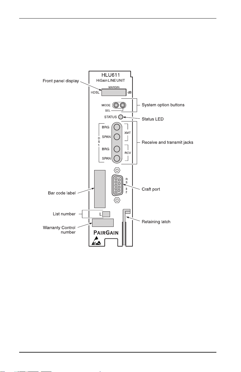
HLU-611 Card-Edge Connectors .....................................5
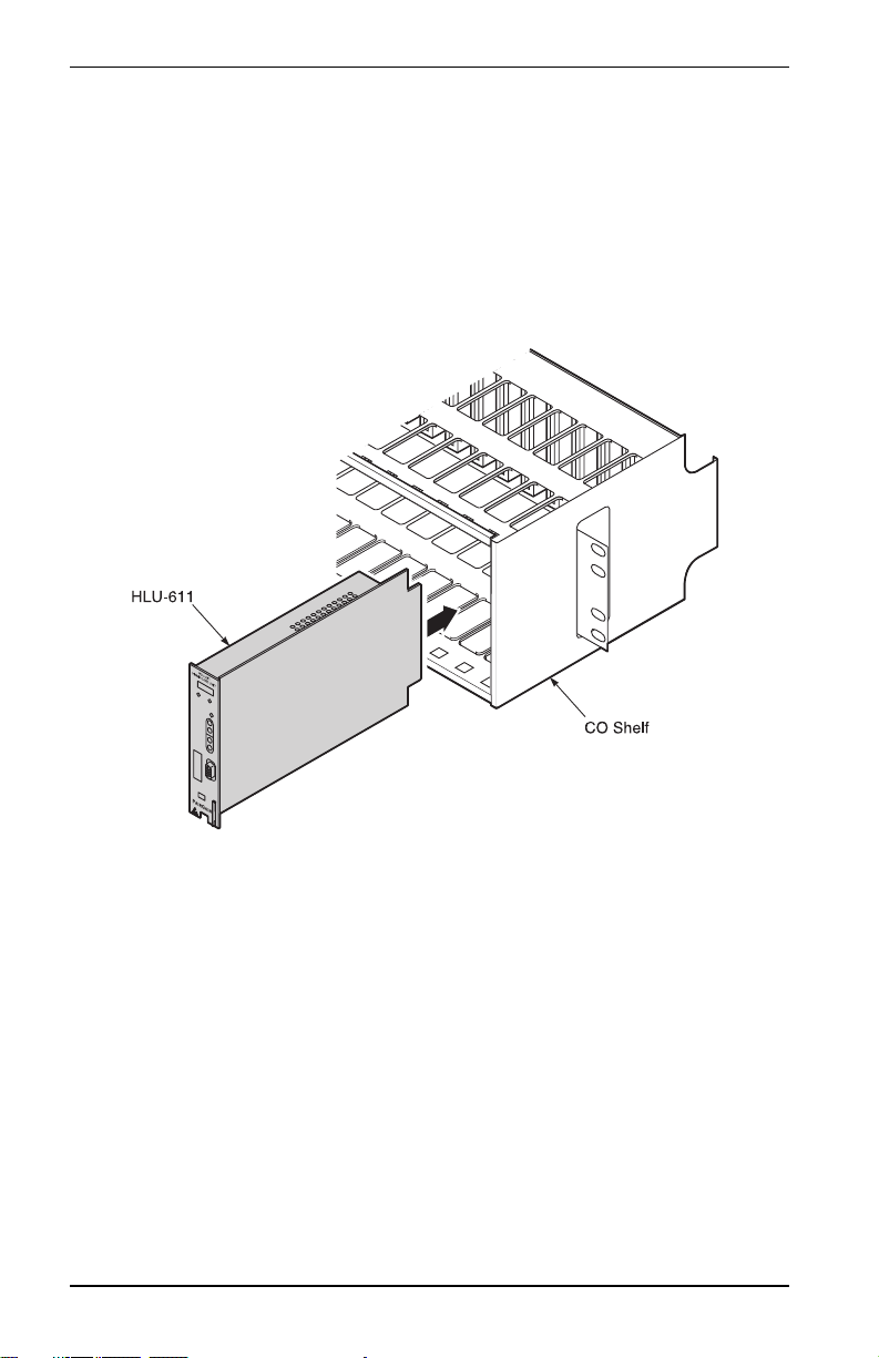
Installing the HLU-611.....................................................6
Provisioning............................................................................7
Using the SEL and MODE Front Panel Buttons ..............7
Default Settings.................................................................7
Using the Craft port ..........................................................8
System Options Settings...................................................9
Testing...................................................................................13
Alarms.............................................................................13
Loopbacks.......................................................................14
Four-Character Diagnostic Messages.............................16
Specifications........................................................................17
Documentation .....................................................................18
Technical Support................................................................18
Bulletin Board Services ..................................................18
Copyright © 1998 PairGain Technologies, Inc.
PairGain is a registered trademark and HiGain is a trademark of PairGain Technologies,
Inc.
Information contained in this document is company private to PairGain Technologies, Inc.,
and shall not be modified, used, copied, reproduced or disclosed in whole or in part without
the written consent of PairGain.
Other product names mentioned in this practice are used for identification purposes only
and may be trademarks or registered trademarks of thier respective companies.

350-611-101-01 March 17, 1998 Revision 01
HLU-611 List 1 PairGain Engineering - Plant Series 1
INTRODUCTION
The PairGain® HiGain™ Line Unit Model HLU 611 Issue 1 List 1 (Part
Number 150-1217-01) is the Central Office (CO) side of a repeaterless T1
transmission system.It isused inconjunctionwith theHRU-612 RemoteUnit
to provide a complete HiGain Very High-bit-rate Digital Subscriber Line
(VHDSL) system on one non-loaded copper pair over the cable lengths
shown in the following table at the line rate of 392 kHz.
.
For more detailedinformation consult the HLU-611 List 1Technical Practice
(Section Number 150-611-101).
Cable Gauge Loss @ 392
kHz dB/kft
Ohms per
kft
Maximum Loop for
35 dB Loss
Ohms @
Maximum Loop
Length
26/0.4 mm 4.97 83.3 7.0 kft/2.13 km 583
24/051 mm 3.87 51.9 9 kft/2.74 km 467
22/0.61 mm 3.01 32.4 12 kft/3.66 km 389
19/0.91 mm 2.17 16.1 16 kft/4.87 km 358
The HLU-611 does not support doublers.

Revision 01 March 17, 1998 350-611-101-01
2 PairGain Engineering - Plant Series HLU-611 List 1
Features
The HLU-611 List 1 Line Unit front panel features are:

350-611-101-01 March 17, 1998 Revision 01
HLU-611 List 1 PairGain Engineering - Plant Series 3
The HLU-611 List 1 front panel components are:
Name Function
Front panel display Four character LCD that provides status messages for VHDSL,
S/N margin, optional settings and alarms.
System
option buttons
MODE and SEL (Select) buttons used to set system modes.
Status LED Tri-color LED that indicates system state:
Green Normal Operation
Flashing Green VHDSL Acquisition
Flashing Red Minor Alarm
Red FUSE ALRM
Yellow Self Test in progress or an HLU-611
List1 loopback in effect (CREM) or
(NLOC)
Flashing Yellow The HLU-611intelligent loopback is in
an ARMED state
Receive (RCV) and
Transmit (XMT)
Splitting access and bridging “210-Bantam” type jacks.
Craft port RS-232 connector that provides access to the maintenance,
provisioning, and performance monitoring interface through a
dumb terminal.
Retaining latch Secures the HLU-611 to the shelf in which it is installed.

Revision 01 March 17, 1998 350-611-101-01
4 PairGain Engineering - Plant Series HLU-611 List 1
Compatibility
The HLU-611 List 1 is designed to mount in the following shelves:
•200-configuration Office Repeater Bay (ORB) shelf or equivalentSmall
Cross Section Shelf (SXSS)
•Kentrox T-Term
•Wescom 342-30 shelves
•PairGain HCS-418 (19”) shelf
•PairGain HCS-417 (23”) shelf
•PairGain HCS-402 (2 slot) shelf
INSTALLATION
Upon receipt of the equipment, visually examine it for signs of damage. If the
equipment has been damaged in transit, immediately report the extent of
damage to the transportation company and to PairGain Technologies. For
PairGain Technical Assistance 24-hours-a-day, 7-days-a-week, contact the
Customer Service Engineering group at (800) 638-0031 or (714) 832-9922 or
fax the group at (714) 832-9924.

350-611-101-01 March 17, 1998 Revision 01
HLU-611 List 1 PairGain Engineering - Plant Series 5
HLU-611 Card-Edge Connectors
The HLU-611 List 1 card-edge connector pinouts are shown below. The
HLU-611 List 1 uses pins 20 and 21 as alarm-relay output. The Kentrox 220
T-Termshelfusesthe samepinsforexternalequalizer output.Ifthe HLU-611
is installed into a Kentrox shelf, the HLU-611 ALM option must be disabled.

Revision 01 March 17, 1998 350-611-101-01
6 PairGain Engineering - Plant Series HLU-611 List 1
Installing the HLU-611
To install the HLU-611 List 1 into the shelf, slide the unit into the shelf card
guides for the desired slot. Push the unit in until it is entirely within the card
guide. The retaining latch locks into place, indicating that the unit is properly
seated.

350-611-101-01 March 17, 1998 Revision 01
HLU-611 List 1 PairGain Engineering - Plant Series 7
PROVISIONING
The HLU-611 List 1 contains a non-volatile RAM (NVRAM) which stores
the system option settings. The options are set from the buttons on the front
panel, or through the RS-232 interface. They are retained if shelf poweris lost
or if the HLU-611 List 1 is unplugged. See page 9 for the HLU-611 List 1
System Options table.
Using the SEL and MODE Front Panel Buttons
To provision the HLU-611 List 1 through the SEL and MODE front-panel
buttons:
1Press the MODE button for approximately one second. The message
displayedonthe front panelalternates betweenthe firstsystemparameter
and its current setting.
2Pressthe SELbutton to step the display through all possible settings (one
at a time) of the parameter being displayed.
3Press the MODE button to select the desired parameter and move to the
next parameter. After you haveconfigured the last parameter, the display
prompts you to confirm the settings.
4Do one of the following:
•Press the SEL button to install the settings.
•Press the MODE button to bypass the settings.
•If neither button is pressed in 30 seconds, the settings are bypassed.
Default Settings
To return the system options back to the original factory default settings:
1Press the SEL button until the DFLT NO message appears.
2Press the SEL button again and DFLT YES displays indicating the
factory default values are now in effect.
To terminate the DFLT mode without setting the factory default values,
press the MODE button or do nothing for 30 seconds.

Revision 01 March 17, 1998 350-611-101-01
8 PairGain Engineering - Plant Series HLU-611 List 1
Using the Craft port
The Craft port, a 9-pin RS-232 connector, on the HLU-611 front panel allows
you to use a standard RS-232 cable to connect your system to a dumbterminal
or PC running a terminal emulation program. Once connected you can access
the maintenance, provisioning, and performance screens.
To provision the HLU-611 through the Craft port:
1Configure the dumb terminal to the following communication settings:
•1200 to 9600 baud (9600 baud is recommended)
•Parity: NONE
•8 data bits
•1 stop bit
•Hardware Flow Control set to NONE
•VT Terminal Emulation
2Use a serial cable to connect the RS-232 COM port on the dumbterminal
to the HLU-611 front panel Craft port.
3On each screen, enter the key represented by the letter in parenthesis for
the parameter to be changed.
•Each entry of this letter scrolls the parameter to its next value.
•After all selections have been made, press to exit and to
confirm the changes. This activates the new choices and returns
control to the Main Menu screen.
The following three useroptions must be set via the dumb terminal interface:
Circuit ID, Time and Date, DS0 Blocking, and Margin Alarm Threshold.
If using the Microsoft Windows terminal emulation program,
from the Settings, Terminal Preference menu, deselect
Show
Scroll Bars
and
Use Function
,
Arrow
, and
Ctrl Keys for
Windows
.
E C

350-611-101-01 March 17, 1998 Revision 01
HLU-611 List 1 PairGain Engineering - Plant Series 9
System Options Settings
The asterisks (*) in the following system settings descriptions indicate the
factory default settings. To return the HLU to the default settings, press the
SEL button for 6 seconds. The Margin threshold and DSX blinking options
must be set from the RS-232 port. All other options can be set from either the
front panel or RS-232 port.
HLU-611 List 1 System Options
Mode Selection Description
EQL EXT* Replaces the internal equalizer with a 12 Vpk-pk drive source for
an external equalizer.
0Sets the equalizer to DSX-1 for 0 - 133 feet.
133 Sets the equalizer to DSX-1 for 133 - 266 feet.
266 Sets the equalizer to DSX-1 for 266 - 399 feet.
399 Sets the equalizer to DSX-1 for 399 - 533 feet.
533 Sets the equalizer to DSX-1 for 533 - 655 feet.
ZBTS ON Selects the Extended Superframe (ESF) frame ZBTSI mode.
OFF* Deselects the ESF frame ZBSTI mode.
LPBK DIS Configures the HLU-611 to ignore the 2 in 5 Smart-Jack
loopback command.
ENA* Enables the HLU-611 to respond to the 2 in 5 Smart-Jack
loopback command.
LBTO NONE Disables automatic time-out cancellation of all loopbacks.
20 Sets automatic cancellation of all loopbacks to 20 minutes
after initiation.
60* Sets automatic cancellation of all loopbacks to 60 minutes
after initiation.
120 Sets automatic cancellation of all loopbacks to 120 minutes
after initiation.

Revision 01 March 17, 1998 350-611-101-01
10 PairGain Engineering - Plant Series HLU-611 List 1
ESAL 17 Closes the alarm relay contacts across pins 20 and 21 and
flashes the red STATUS LED when 17 ES (17 HDSL CRC errors
on either HDSL loop or a total of 17 BPVs) occur within a
24-hour period.
170 Closes the alarm relay contacts across pins 20 and 21 and
flashes the red STATUS LED when 170 ES (170 HDSL CRC
errors on either HDSL loop or a total of 170 BPVs) occur within
a 24-hour period.
NONE* Prevents generation of an alarm due to excessive Errored
Seconds.
SPLB GNLB Configures the HiGain system to respond to the generic (3/4/
5/6 in 7) in-band loopback codes.
A1LB and
A2LB*
Configures the HiGain system to respond to the Teltrend
addressable repeater in-band loopback codes.
A3LB Configures the HiGain system to respond to the Wescom
addressable repeater in-band loopback codes.
A4LB Configures the HiGain system to respond to the Wescom Mod
1 addressable repeater in-band loopback codes.
A5LB Configures the HiGain system to respond to the Teltrend Mod
1 addressable repeater in-band loopback codes.
PWRF DIS Disables powering to the HRU-612 over the HDSL pairs.
ENA* Enables powering to the HRU-612 over the HDSL pairs.
DS1 B8ZS Places both the HLU and HRU into their B8ZS modes.
AMI* Places both the HLU and HRU into their AMI modes.
AUTO The AUTO mode is not supported. If selected, the DS1 code
defaults to AMI.
HLU-611 List 1 System Options (Continued)
Mode Selection Description

350-611-101-01 March 17, 1998 Revision 01
HLU-611 List 1 PairGain Engineering - Plant Series 11
FRMG AUTO* Configures HiGain to operate in an auto-framing (AUTO) mode
in which it continuously searches the input T1 bit stream for a
valid Superframe or Extended Superframe pattern. This feature
is required for fractional T1 applications (DS0 blocking) where
it insures proper channel time slot alignment. While HiGain can
also process unframed data in this AUTO mode, it is
recommended that the UNFR mode be used for all unframed
applications. Using the AUTO mode for unframed applications
runs the risk of detecting òpseudo validó frame sequences,
which can affect the data integrity.
UNFR Configures HiGain to operate in an unframed mode. This mode
disables the auto framing process and forces HiGain to
function as a transparent bit pipe.
HAIS 2LP* Causes HiGain to transmit the AIS signal at both the HLU and
HRU T1 output ports when both of the HDSL loops are not in
sync (LOSW).
1LP Cause HiGain to transmit the AIS signal at both the HLU and
HRU T1 output ports when either of the two HDSL loops are
not in sync (LOSW) or if a margin alarm occurs.
CONF YES Confirms that all twelve operating modes (listed above) are to
be updated to their current selections.
NO* Prevents the most recently selected operating mode selections
from being updated. They remain as they were before the
system option settings mode was entered.
SAIS ENA* Causes the HRU-612 to transmit the AIS signal towards the
Network Interface (NI) when in NREM or Smart-Jack loopback.
DIS Causes the List 1 HRU-612 to transmit the signal from the
network towards the NI and the HRU-612 List 2 to open and
terminate its RCV NI port when an HRU NREM or Smart-Jack
loopback is executed. The AIS signal is off.
DS0 BLK The DS0 blocking option can only be set via the RS-232
maintenance port with a terminal. The 4-character HLU-611
List 1 front panel LED readout only displays the status of the
blocking option. BLK indicates at least one channel is blocked.
NONE* NONE indicates no channels are blocked.
HLU-611 List 1 System Options (Continued)
Mode Selection Description

Revision 01 March 17, 1998 350-611-101-01
12 PairGain Engineering - Plant Series HLU-611 List 1
MARgin
Alrm Thrs
0 to 15 dB The Margin Alarm Threshold can only be set via the RS-232
maintenance port with a terminal. It determines the minimum
allowable margin below which a minor alarm can occur.
4 dB* (Default value)
ALM DIS* Opens the relay alarm contacts, if closed, and prevents another
relay alarm closure from occurring.
ENA Enables activation of the minor alarm relay when a minor alarm
condition occurs.
*Indicates HLU-611 factory (default) settings.
HLU-611 List 1 System Options (Continued)
Mode Selection Description

350-611-101-01 March 17, 1998 Revision 01
HLU-611 List 1 PairGain Engineering - Plant Series 13
TESTING
Minor alarm and diagnostic messages routinely appear on the
HLU-611 List 1 front-panel four-character display. This display turns on
when power is initially applied to the HLU-611 List 1. To conserve power,
the display only remains on for five minutes if neither the MODE or SEL
buttons are pressed. The use of either button activates the 4-character display
and restarts the 5-minute power-control timer.
Alarms
Only one alarm can be displayed at a time, therefore, only the highest priority
alarm is displayed if more than one alarm exists. The following table lists the
alarms ordered by priority.
Status Menu Alarms Messages
Message Full Name Description
NONE No Alarms
LLOS Local Loss
of Signal
No signal from HLU-611 List 1 local T1 interface.
RLOS Remote
Loss of
Signal
No signal from HRU-612 remote T1 interface.
LOSW Loss of
Sync Word
The VHDSL’s loop has lost sync.
HES VHDSL
Errored
Second
The VHDSL CRC count has exceeded the user-selected ES
threshold.
DS1 Digital
Service 1
DS1 input BPVs at the HRU-612 have exceeded the user
selected ES threshold.

Revision 01 March 17, 1998 350-611-101-01
14 PairGain Engineering - Plant Series HLU-611 List 1
Loopbacks
The HLU-611 List 1 loopback messages are listed in the following table.
Loopback Messages
Message Full Name Description
SMJK Smart-Jack Loopback Loopback at HRU toward the CBA initiated by either
the (2 in 5) in-band loopback code or the out-of-
band ESF data link code.
NREM Network Remote
Loopback
Loopback at HRU toward the CBA initiated by
upstream in-band codes or from the maintenance
terminal.
NLOC Network Local
Loopback
Loopback at HLU toward the CBA initiated by
upstream in-band codes or from the maintenance
terminal.
CLOC Customer Local
Loopback
Loopback at HRU toward CI initiated from CPE
(customer) by in-band codes or from the
maintenance terminal.
CREM Customer Remote
Loopback
Loopback at HLU toward customer initiated from
CPE (customer) by in-band codes or from the
maintenance terminal.
ARM Armed The HiGain system detected the IR loopback
(2 in 5) arming code.
TLOS Transmit Loss of
Signal (Loopback)
HRU is in a logic loopback state caused by a loss of
its T1 input from the CI, if enabled at the HRU via its
TLOS switch option.

350-611-101-01 March 17, 1998 Revision 01
HLU-611 List 1 PairGain Engineering - Plant Series 15
A block diagram showing the GNLB locations and their activation codes are
shown below.

Revision 01 March 17, 1998 350-611-101-01
16 PairGain Engineering - Plant Series HLU-611 List 1
Four-Character Diagnostic Messages
The HLU-611 List 1 diagnostic messages are listed in the table below.
Four-Character Diagnostic Messages
Message Full Name Description
FERR Framing Bit Error
Occurred
Framing bit error occurred at HLU T1 input.
LBPV Local Bipolar Violation A bipolar violation has been received at the T1
input to the HLU-611.
SIG Signal The HLU & HRU transceivers are trying to
establish contact with each other.
ACQ Acquire The HLU & HRU multiplexers are trying to
establish synchronization over each.
ACO Alarm CutOff A minor alarm has occurred, and been retired to
an ACO condition, by pressing the SEL button on
the HLU front panel.
Self Test The HLU is in a self test mode. This occurs every
power ON/OFF cycle.
ALRM Alarm Condition Exists A minor alarm condition is in effect.
M=X VHDSL Loop Margin Indicates the power of the received VHDSL signal
on each Loop relative to noise. Any value of ‘06’
or greater is adequate for reliable system
operation.
PWR FEED
SHRT
Power Feed Short Indicates a short across the VHDSL pairs in span
1. This same message can occur with an HRU
that is drawing the correct amount of power over
good cable pairs but cannot communicate with
the HLU.
PWR FEED
OPEN
Power Feed Open Indicates an open circuit in the T&R of either
VHDSL pair.
PWR FEED
OFF
Power Feed Off VHDSL span power has been turned off.
BAD RT? No response from HRU The HLU does not receive any response from the
HRU. Thus, the HRU’s integrity is questionable.

350-611-101-01 March 17, 1998 Revision 01
HLU-611 List 1 PairGain Engineering - Plant Series 17
SPECIFICATIONS
Power Consumption
14 Watts (typical); 18 Watts (maximum)
Heat Dissipation
6 Watts (typical) 8 Watts (maximum)
Mounting
220 Mechanics
Dimensions
Height: 5.6” (15 cm)
Width: 1.4” (3.5 cm)
Depth: 10” (25.4 cm)
VER HLU Software
Version #
This is displayed during the System Settings
review mode. Depress the MODE button for 3
seconds to enter System Settings review mode.
LIST 0xL HLU’s List # Displayed during System Settings review mode
defined above.
FRM Frame: SF, ESF, UNFR,
NONE
Defines the type of frame pattern being received
from the DSX-1. Displayed during System
Settings mode defined above.
CODE Line Code: AMI, B8ZS This is the line code that the HLU is set to receive
and transmit at its DSX-1 interface. Displayed
during System Settings mode defined above.
DS0 DS0 Blocked Channels Indicates status of DS0 blocked channels. NONE
indicates no channels are blocked. BLK indicates
some channels are blocked.
Four-Character Diagnostic Messages (Continued)
Message Full Name Description

Revision 01 March 17, 1998 350-611-101-01
18 PairGain Engineering - Plant Series HLU-611 List 1
DOCUMENTATION
The HLU-611 List 1 has a complete technical practice that you can download
from the PairGain Technical Manuals Web page at: www.pairgain.com. A
password is required. If you do not have a password, contact your PairGain
sales representative.
If you have any comments on any PairGain documentation, send mail to
technical_publications@pairgain.com. Type the product name and the
section number of the document in the subject area of the email message.
TECHNICAL SUPPORT
PairGainTechnicalAssistanceisavailable24-hours-a-day,7-days-a-weekby
contacting PairGain Customer Service Engineering group at:
During normal business hours (8:00 AM to 5:00 PM, Pacific Time, Monday-
Friday, excluding holidays), technical assistance calls are normally answered
directly by a Customer Service Engineer. At other times, a request for
technical assistance is handled by an on-duty Customer Service Engineer
through a callback process. This process normally results in a callback within
30 minutes of initiating the request.
Bulletin Board Services
PairGain maintains a computer bulletin board system for obtaining current
information on PairGain products, product troubleshooting tips and aids,
accessing helpful utilities, and for posting requests or questions. This system
is available 24-hours-a-day by calling (714) 730-3299. Transmission speeds
up to 28.8 kbps are supported with a character format of 8-N-1.
Telephone: (800) 638-0031 or (714) 832-9922
Fax: (714) 832-9924
This manual suits for next models
1
Table of contents