Thunderbird BD20 Guide

THUNDERBIRD
Electric Fence Systems
Models BD20
Battery Powered Energi er
NOTE: READ ALL INSTRUCTIONS INCLUDING HELPFUL HINTS BROCHURE
BEFORE USING THIS FENCE ENERGIZER.
Thunderbird's battery range of energi ers are highly efficient electrical appliances. Installed
and used correctly, these products should provide years of reliable service. These energi ers
have protection against moisture and ant damage.
WARNING:-
1. Regular inspections of electric fences must be undertaken to ensure continued op-
erational safety and compliance. See - ‘INSTRUCTIONS FOR INSTALLATION AND
CONNECTION OF ELECTRIC FENCES FOR ANIMALS’ detailed over the page.
2. Persons coming into contact with high voltage pulses on a high output connection
may have their normal physiological functions interrupted.
3. Young children and infirm persons should not be left unsupervised in the vicinity of
an electric fence energi er or fence.
4. Do not connect to mains operated equipment.
5. Do not use copper wire. Electrolysis will occur and cause problems over time.
6. Output voltage reduces when the battery is near flat.
INSTRUCTIONS
Place the energi er in a suitable position for connection to the fence, preferably at the middle
of the fence line. Drive one or more galvanised earth stakes into the ground approximately
1m. Connect the live wire to the fence or red terminal, and the earth stake to the earth or
green terminal. Once all the fence has been installed, connect the red battery clip to the posi-
tive terminal of a 12V battery and the black clip to the negative terminal.
Correct earthing is extremely important. It is the other half of the electric fence. In dry con-
ditions or sandy soil, run an earth wire as well as the live wire as part of the fence, connect
any existing fence to the earth stakes, and drive in extra earth stakes every 1.5km. This ener-
giser has intelligent battery monitoring, if the battery starts getting flat the output voltage will
reduce to conserve the battery.
The top light flashes with every energi er pulse. The bottom light is a low voltage indication
that flashes with every pulse if battery voltage falls below 12.0V (nominal). If the battery
voltage falls to approximately 11.5V the low battery light will give a double flash every
pulse. Once the battery voltage falls to 11V the energi er will stop and the low battery light
will be continuously on. The energi er will start operating normally again when the battery
voltage exceeds 12V. These cutouts are intended to protect your battery.
These energi ers have built in self testing. If there is a problem with the unit you will see
multiple flashes with each pulse. If the energi er pulse light flashes normally, and there is
low or no output, assume that there is a problem with the fence.
WARRANTY
THUNDERBIRD
Elec ric Fence Sys ems.
Thunderbird warrants all electric fence energi ers against defective
workmanship and faulty materials for 2 years from the date of purchase.
We undertake, at our option, to replace or repair free of charge each
product, or part thereof, on condition that it is returned to our factory
freight pre paid, and found on examination to be suffering from material
or constructional defect.
We cannot be held responsible for any repair other than those carried out
by us or our authorised agents.
A proof of purchase mus be re urned wi h he goods if you are
claiming warran y. This can be in the form of a photocopy of your re-
ceipt. No warranty claim will be accepted without this information.
This warranty is void if the product is subjected to improper use or han-
dling, incorrect power input voltage, damage through contact with
chemicals, flooding, fire, explosion, excessive heat, lightning strikes,
insect damage, or damage to external wiring.
Country Electronics Pty Ltd
ABN 38 003 806 040
11 Industrial Avenue P.O. Box 391,
Mudgee NSW 2850 Mudgee NSW 2850
PHONE 02 63723600
FAX 02 63722597 Email : sales@thunderbird.net.au
For your records.
Model ……………………………………………………………………………
Serial No ………………………………………………………………………..
Da e of purchase…………………………………………………………………
Place of purchase ………………………………………………………………..
Receip No ………………………………………………………………………..

INSTRUCTIONS FOR INSTALLATION AND CONNECTION OF ELECTRIC FENCES FOR ANIMALS.
The following safety information is part of the Australian standard AS/NZS 60335.2.76:2003 amend-
ment 2. Refer to AS/NZS 3014:2003 for full details on electric fence installation.
>Electric fences must be installed and operated so that they do not cause an electrical ha ard to per-
sons, animals or their surroundings.
>Construction of electric fences that is likely to lead to the entanglement of animals or persons is to be
avoided.
>An electric fence must not be supplied from two separate energi ers of from independent fence cir-
cuits of the same energi er.
>For any two separate electric fences that are each supplied from a separate independently timed ener-
gi er, the distance between the wires of the two fences must be at least 2 metres. If this gap is to be
closer, it must be effected by means of electrically non-conductive (insulating) material or an isolated
metal barrier.
>Barbed wire or ra or wire must not be electrified by an energi er.
>A non-electrified fence incorporating barbed or ra or wire may be used to support one or more off-set
electrified wires of an electric fence. The supporting devices for the electrified wires must be con-
structed so as to ensure that these wires are positioned at a minimum distance of 150mm from the ver-
tical plane of the non-electrified wires. The barb or ra or wire is to be earthed at regular intervals in
accordance with Thunderbird’s earthing recommendations.
>A distance of a least 10 metres must be maintained between the energi er’s earth electrode and any
other earthing system connected parts—for example mains power protective earth or telecommunica-
tion system earth.
>Electric fence connecting leads located inside buildings must be effectively insulated from the
earthed structural parts of the building, for example, use suitable high voltage insulated cable.
Impor an : always ensure metal parts of the building are effectively earthed.
>Electric fence connecting leads located underground must be run in suitable conduit of insulating
material or high voltage cable to be used. Care must be taken to ensure that the effects of animal
hooves or vehicle wheels (e.g. tractor) sinking into ground cannot damage connecting leads.
>Electric fence connecting leads must not be installed in the same conduit as the mains power supply
wiring, communication cables or data cables.
>Crossing with overhead power lines must be avoided wherever possible. If such a crossing cannot be
avoided it must be made underneath the power line and as near as possible at right angles to it.
>If electric fence connecting leads and wires are installed near an overhead power line, the clearances
must not be less than indicated in the table below.
Power line voltage - V Clearances - Metres
Up to 1,000 V 3
1,000 V - 33,000 V 4
Greater than 33,000 V 8
>
If electric fence connecting leads and wires are installed near an overhead power line, their height
above the ground must not exceed 3 metres. This height applies either side of the orthogonal projection
INSTRUCTIONS FOR INSTALLATION AND CONNECTION OF ELECTRIC FENCES FOR ANIMALS.
of the outermost conductors of the power line on the ground surface, for a distance of ;-
- 2 metres for power lines operating at nominal voltage not exceeding 1000V.
- 15 metres for power lines operating at a nominal voltage exceeding 1000V.
>Electric fences intended for deterring birds, household pet containment or training animals such as
cows need only be supplied from a low output energi er to obtain satisfactory and safe performance.
>For electric fences intended for deterring birds from roosting on buildings, no electric fence wire shall
be connected to an earth electrode. A warning sign must be fitted to every point where a person or
persons may gain access to the conductors.
>Where an electric fence crosses a public pathway, a non-electrified gate must be incorporated in the
electric fence at that point or a crossing by means of stiles must be provided. At any such crossing, the
adjacent electrified wires must carry warning signs.
>Any part of an electric fence that is installed along a public road or pathway must be identified at
frequent intervals by warning signs securely fastened to the fence posts or firmly clamped to the
fence wires.
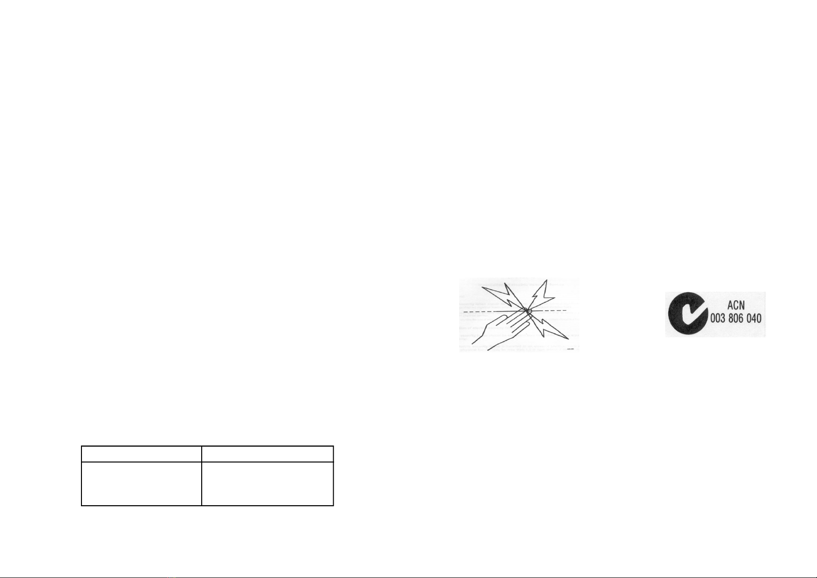
>The si e of the warning sign must be at least 100mm x 200mm. The background colour of both sides
of the warning sign is to be yellow. The inscription on the sign is to be black and shall be either the
symbol shown (Fig. 1 ) or the words - “WARNING - ELECTRIC FENCE”
>The lettering must be indelible, be on both sides of the sign and in letters not less than 25mm in
height.
>Ensure at all times that a mains operated, ancillary equipment connected to the electric fence circuit
provides a degree of isolation between the fence circuit and the supply mains equivalent to that pro-
vided by the fence energiser.
>This energiser mus be ins alled in accordance wi h he s andard AS/NZS 3014:2003.
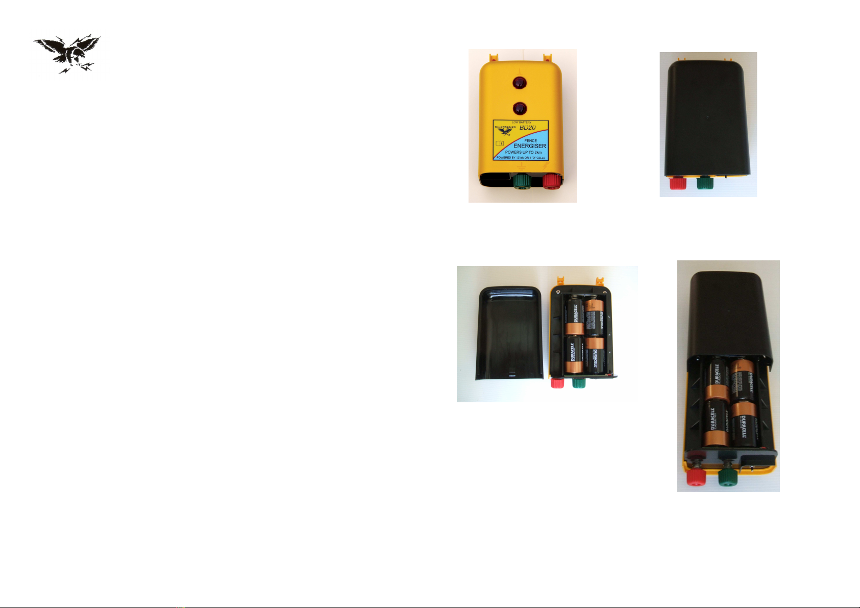
SPECIFICATIONS
Input Voltage 12.7V nominal - Maximum 20.0V
Input Current BD20 - 15mA (nominal) @12.5 volts: 30mA @ 6 volts
Output Voltage 7.5kV (nominal)
Stored Energy BD20 - 0.15 joules
NOTE: Hot tape and polywire can be used effectively for lengths up to 500metres from the
energi er. Super hot tape and super polywire can be used on runs up to 1500m. Use galva-
nised fencing wire for longer distances.
Fig. 1

Low and High power levels.
A low and high power level switch is fitted for extra battery conservation, this is located at the
base of the energiser.
The BD20 can hang on the wire, we recommend a screw or a piece of tie wire be placed and
tied through one of the holes in the mounting lugs, to secure.
When operating from an external 12 volt battery, ensure D cell batteries are removed.
Ins alling D cell ba eries.
The system will operate up to 5 weeks on low power with fresh alkaline D cell batteries (4).
To install D cell batteries, remove rear black plastic cover by gently pulling at the bottom
centre of the black cover outwards, then upwards. This disengages the tapered plastic lug in-
side the black rear cover. The cover simply slides off the main case.
Ensure the D cell batteries are placed in the correct polarity ( direction ) as indicated by labels.
When batteries are in position, simply slide the black rear plastic cover back onto the main
case and firmly push back into position to reengage the plastic tapered lug,
Connec ing o an ex ernal 12 vol ba ery.
A 12 volt D.C. battery lead is supplied with the system. Insulated black and red plastic clips
with stainless steel teeth are installed on one end, these connect to the 12 volt battery
terminals. The other end of the lead has a D.C. plug, this simply pushes into the D.C. socket
located at the base of the energiser, next to the low / high power switch.
Connec ion o ear h s ake and fence / live wire.
A green earth lead with an insulated clip and a ring is supplied, simply undo the green earth
knob from the terminal at the base of the energiser and place the ring over the bolt. Screw the
green knob back onto the terminal bolt firmly, to connect ring end.
Clip the green insulated clip to the galvanised earth stake that has been driven into the ground.
A red fence / live wire lead with an insulated clip and a ring is supplied, undo the red knob
from the fence terminal at the base of the energiser, place ring over the terminal bolt and
tighten red knob firmly against ring end.
Connect the red clip to the live insulated wire.
BD20 Battery powered fence energiser
Front of case Rear of case
Rear plastic cover with batteries fitted
Slide rear cover on or off
Other Thunderbird Power Supply manuals
Popular Power Supply manuals by other brands

Altronix
Altronix AL168 Series installation guide

Altronix
Altronix ALTV244220 Series installation guide

Matsusada Precision
Matsusada Precision ECA Series instruction manual

Altronix
Altronix eFlow104NB installation guide

Allied Telesis
Allied Telesis AT-PWR3202 installation guide

multicomp pro
multicomp pro MP710079 user manual

Siemens
Siemens GAMMA N 125/02 Operating and mounting instructions

Pulsar
Pulsar PSCV3512 quick start guide

Antec
Antec EA-650 Platinum user manual

Jupiter
Jupiter EX Series quick start guide

ENERMAX
ENERMAX REVOLUTION 87+ ERV550AWT-G user manual

Safety Vision
Safety Vision Observer 4000 HV Hardware user's guide