Cornerstone UPS 933-4110 User manual

HO Structure Kit
UPS®HUB WITH
CUSTOMER CENTER
933-4110
© 2017 Wm. K. Walthers, Inc., Milwaukee, WI 53218 waltherscornerstone.com I-933-4110 Printed In Taiwan
6
13
213
2
13
2
13 313
12
42
43
24
44 x6
26 x6
25
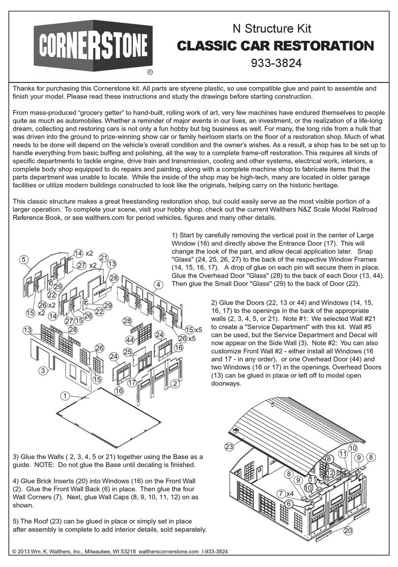
Thanks for purchasing this Cornerstone kit. All parts are styrene plastic, so use compatible glue and paint to assemble and
finish your model. Please take a few minutes to read these instructions and study the drawings before beginning. PLEASE
NOTE This model is based on ³tip-up² buildings in use since the 1980s, and like the prototypes, consists of interchangeable
wall panels that can be arranged as desired to customize your structure. These instructions cover a typical assembly, however
you can use fewer parts to make a smaller structure, or combine complete kits and matching Truck and Railroad Docks wall
panels (#933-4070 sold separately) for a bigger building. The SceneMaster Modern Wall Light 3-Pack #949-4318, sold sepa-
rately) may be used in place of the five nonworking light fixtures (57); to assemble your model as shown here, you¹ll need two
sets. For ease of assembly, you may wish to have these additional parts on hand before starting. Some parts included in this
kit are not needed for assembly, and can be kept for future projects or discarded as desired.
Starting operations as the American Messenger Service from a single basement office in 1907, 19-year old James Casey laid
the foundation for what would become United Parcel Service. Today UPS centers like this can be found in many industrial and
commercial areas, providing shippers with convenient service and expedited delivery to destinations around the world. Your
new model is typical of larger facilities that transfer packages for both long-distance and local delivery, handling trailers as well
as drive-in loading for Package Cars and light trucks. A convenient service center is also provided where customers can quickly
ship smaller packages. To bring your new UPS Hub with Customer Service Center to life, SceneMaster offers 20 officially
licensed UPS vehicles to model delivery services, and for the finishing touch, add the UPS Personnel with Hand Cart figure set
(#949-6043) each sold separately. For additional ideas and supplies, see your local hobby shop, check out the latest Walthers
Reference Book, or visit us online at walthers.com.
BEFORE STARTING...
All wall panels are glued together on the back using molded locater pins and separate connector plates as shown. A raised
ridge is molded at the bottom to align with the base: double walls also have a raised ridge at the top to support the roof, and
corner walls have a third raised ridge along the outside edge. When assembling wall sections, work on a flat surface and allow
parts to dry.
TRAILER LOADING DOCK - Assemble from Left to Right
1) Begin by gluing Steel Entry Door (25) to opening in
rear of Entry Panel Wall (6).
2) PLEASE NOTE: Optional Canopies (6x 65) are provid-
ed for each truck door (see last page for illustration); if
you wish to use these parts, drill out mounting holes on
the backs of Walls (2) using a .060" (1/16" 1.5mm) bit -
canopies will be installed in step 15. When assembling
the Truck Dock Door Panels (2, three shown), the Truck
Doors (6x 26, two per wall) can be left off to model an
open door: for a closed door, glue Overhead Door Glass
(2x 44 per door - six total) to rear of Truck Doors.
3) Assemble the Double Office Wall (12) by gluing the
Glass Entry Door (42) and Large Window (43) in place:
both use Large Glass (24): align Glass with locating pins
on back of frames and glue where parts meet.
4) Work on a flat surface and connect individual wall
sections (6, 3x 2, 3 &
12) by aligning openings in Large Connector (5x 13) with
raised pins on back of walls and gluing where parts meet
as shown.

1
14 8
14 3
14 8
14 3
14 8
14 3
14 8
14
3
15
915
15
915
15
9
15
15
9
15
39
44
39
44
39
44
39
44
5
13 6
13
4
25
5
13 11
13 4
21
23
DRIVE-IN DOCK
PLEASE NOTE: When planning for installation on your
layout, this area will require building a raised approach or
ramp. Assemble this wall from left to right as shown:
5) Glue Medium Connector (14) to mounting pins at top
right of Double Panel Plain Wall (1) and Small Connector
(15) to pin on lower right edge as shown.
6) Working on a flat surface, assemble four drive-in dock
walls: Align Medium Connectors (8x 14) with pins at tops of
Small Dock Upper Panels (4x
8) and glue where parts meet. Align Small Connectors (8x
15) with pins on Small Dock Lower Panels (4x 9), Double
Panel (1) and Single Panel Walls (4x
3) as shown, and glue where parts meet.
7) Overhead Doors (4x 39) can be left off to model an open
door: for a closed door, glue Overhead Door Glass (2x 44
per wall, eight total) to rear of each Double Overhead Door.
Glue completed doors to openings between Panels (8, 9).
REAR WALL
8) PLEASE NOTE: This illustration shows the rear of this
wall assembly; be sure the raised ridges are at the outside
edge of each Corner Wall Panel (4,
5) as shown. Glue Large Connectors (2x 13) to mounting
pins on the plain edge (inside) of both Corner Walls as
shown. Align pins on left and right of Single Panel Entry Wall
(6) with openings in Large Connectors, and glue where
parts meet. Glue Entry Door (25) to opening as shown.
CUSTOMER SERVICE ENTRY/FRONT WALL
9) PLEASE NOTE: This illustration shows the rear of this
wall assembly; be sure the raised ridges are at the outside
edge of each Corner Wall Panel (4, 5) as shown. Glue
Large Connectors (2x 13) to mounting pins on the plain
edge (inside) of both Corner Walls as shown. Align pins on
left and right of Single Office Wall (11) with openings in
Large Connectors, and glue where parts meet. Align open-
ings on Small Glass (23) with pins on back of Glass Entry
Door (21) and glue together; glue completed door to open-
ing in rear of Single Office Wall.

TRANSFORMER
CABINET
36
35
33
32
34
37
55
52
54
53
50
51
AC UNIT
20
20
16
20
20
19
16
19
17
19
116 or
117
63
64
62
61
114
115
57
61 62
65 x6
28 x6
27 x6
58
60
59
116 or
118
118
BASE SECTIONS
10) The base is designed for easy modification for a longer or short-
er design, however some cutting and splicing will be needed. For a
standard assembly, align corner tabs and slots and glue where
Long (2x 16) and Short (2x 17) Base Sections meet.
MAIN ASSEMBLY
11) Using raised ridges on lower edges of completed wall
assemblies, carefully align and support walls: glue to
Base and at inside corners where parts meet.
EXTERIOR DETAILS
Front Entry
12) PLEASE NOTE: Parts are included
to build two versions of the front stairway
select one:
12A) Standard assembly: Glue Exterior
Panel (62) to outside edge of Stairs (61).
12b) Stairs with Ramp: The Exterior Stair Panel (62)
has molded cut lines at left and right on the back so
Entrance Ramp (63) can be installed on either side as
desired. Carefully remove one end and handrails
from the Exterior Panel outside of the straight pipe at the angles of the pipes. Note the raised ridge on the underside of Entrance
Ramp (63) is the upper end; align with top Stair (61) and modified Exterior Panel and glue parts in place.
Glue Ramp Exterior (64) to outside edge.
12C) Both versions: Align completed steps with large entry door and glue to walls where parts meet.
13) Two styles of UPS Shield Logos are provided; select either the Modern
(116) or Bow Tie (118) Shield and glue in place. Glue Customer Center Nameplate (117) below Shield.
14) PLEASE NOTE: printed signs are provided if you wish to backdate the Roadside Pillar Sign to the bow tie logo - please see
the instructions on the printed sign sheet. Align pins and openings on back of Roadside Pillar Sign and glue halves (2x 115)
together. Align tab on bottom of this assembly with opening in top of Pillar Sign Base (114) and glue where parts meet.
Install completed Pillar alongside the main street entrance.
Trailer Loading Dock:
15) Weather Bellows/Seals (make 6): glue Weather Bellows/Seal (6x 28) to openings as shown. Align pins on Bumpers (6x 27)
with door openings and glue in place. PLEASE NOTE: If you¹re using the optional Canopies (6x 65), and have not already done
so, drill out mounting holes on the backs of Walls (2) using a .060" (1/16" 1.5mm) bit. Glue Canopies in place.
16) Large Stairs: Glue Exterior Panel (62) to outside edge of Stairs (61).
Align completed steps with side entry door and glue to walls where parts meet. PLEASE NOTE: If desired, a working light from
the SceneMaster Modern Wall Light (3-Pack #949-4318, sold separately) may be installed, or glue the nonworking Light Fixture
(57) above entryway as shown.
17) Glue Large Handrail (59) to mounting points in top of Small Stairway (58). Glue End Railing (60) as shown in mounting point
and on inside edge of Large Handrail. Align completed steps with small entry door and glue to wall where parts meet. Select
either the Modern (116) or Bow Tie (118) Shield and glue above entry door as shown.
18) PLEASE NOTE: The Side (4x 20) and End (2x 19) Wall Caps are L-shaped in cross section; align the thin edge on the
inside so the larger edge rests on top of the wall assemblies and glue in place as shown.
19) Pad-Mounted Transformer Cabinet - Using raised ridges on Base (37) to
align Walls (32, 33, 34 & 35), glue to Base and at inside corners where parts
meet as shown. Align inset area on underside of Top (36) with wall assembly
and glue where parts meet.
20) Rooftop AC Units - Make four as follows: note raised ridges on Front
(53) and Side Walls (51, 52) are the bottom and rest on the Base (50). Align
tabs and slots on Front and Side Walls, glue at inside corners where parts
meet and to Base. Glue Rear Wall (54) below angled ridges on both
sidewalls and to Base. Align inset area on underside of Top (55) with wall
assembly and glue where parts meet.

48 x4
47 x4
49 x4
13
13
20
56 x6
18
AC Assembly
Transformer
Assembly 45 38
60
58
59
57
57
57
57
21) Electrical Cabinet with Meters (38): Glue Meter Covers (2x 45) to raised round areas on meter details. The finished Electrical
Cabinet can be installed on any wall with the Transformer alongside or some distance away; depending on your final location,
you may wish to add Protective Posts to alert drivers using the Walthers SceneMaster Safety & Security Posts
(#949-4148) or parts from the Cornerstone Security Details (#933-4076), both sold separately.
22) Glue Large Handrail (59) to mounting points in top of Small Stairway (58). Glue End Railing (60) as shown in mounting point
and on inside edge of Large Handrail. Align completed steps with small entry door and glue to rear wall where parts meet.
23) PLEASE NOTE: If desired, working lights from the SceneMaster Modern Wall Light 3-Pack (#949-4318, sold separately)
may be installed - two sets are needed to build the model as shown with four lights - or glue nonworking Light Fixtures (4x 57)
above each door.
ROOF & DETAILS
24) Connect Rear (18) and Front (20) Roof Halves by gluing Large Connecters (2x 13) to underside of both halves across the
joint as shown. Make sure Roof rests on raised ridges on double wall panels and tops of all Connectors (13, 14): it may be glued
or simply set in place if you wish to add floors, interior details or lighting (all sold separately).
25) PLEASE NOTE: Finish assembly by gluing Vents (4x 47, 4x 48, 4x 49), Roof Drains (6x 56) and four Air Conditioning units
at any point on Roof.
DECALING
1. After cutting out the decal, dip in water for 10 seconds,
remove and let stand for 1 minute. Slide decal onto surface,
position and then blot off any excess water.
2. Lightly brush Micro Sol® on top. This will soften the decal
allowing it to conform to irregular surfaces. DO NOT TOUCH
DECAL while wet!
3. When the decal is thoroughly dry, check for any trapped air
bubbles. Prick them with the point of a small pin or hobby knife
blade and apply more Micro Sol®.
Table of contents
Other Cornerstone Toy manuals
Popular Toy manuals by other brands

Mega Construx
Mega Construx Wonder Builders Pokemon Snubbull manual

Eaelec
Eaelec Studebaker US6 Assembly instructions

Radica Games
Radica Games I7008 Pocket Poker instruction manual

Viessmann
Viessmann 5545 Operation manual

Itsmagical
Itsmagical BeepBeep trucky RC manual

Seagull Models
Seagull Models EXTRA 330LX Assembly manual