CORNING Mid-Power E62-M2RU User manual

Installation Manual | CMA-795-AEN | Page 1
Mid-Power (E62-M2)
Installation Manual
Everon™ 6200
1.
2.
This document describes the installation procedure for the E62-M2 unit.
This is NOT a CONSUMER device. It is designed for installation by FCC LICENSEES and
QUALIFIED INSTALLERS. You MUST have an FCC LICENSE or express consent of an FCC
License to operate this device. NOTE: Only authorized person can enter the area where the
antenna is installed. And the person is fully aware of the potential for exposure and can exercise
control over his or her exposure by leaving the area or by some other appropriate means.
Awareness of the potential for RF exposure in a workplace or similar environment can be provided
through specific training as part of a RF safety program.
GENERAL INFORMATION
The E62-M2RU is a medium-
power remote unit supporting cellular technologies on fiber optic
cable using the CPRI protocol. The M2 is ideal for multioperator multiband deployments of
cellular services in medium-to-large coverage areas. The M2 supports up to 37 dBm output
per band in single 4T4R or dual 2T2R up to 100 MHz per band. The M2 converts an optical
signal to RF and then transmits at the relevant 3GPP band and receives the analog RF signal,
conditions it, and converts it back to optical for routing to the E2 or A2.

Installation Manual | CMA-795-AEN | Page 2
Content
Preface ............................................................................................................................................... 4
Safety Instructions ............................................................................................................................. 4
Site Considerations ............................................................................................................................ 6
Environmental Considerations ........................................................................................................... 6
DC Power Connections ..................................................................................................................... 7
Warning Marks................................................................................................................................... 8
Unpacking and Inspecting ................................................................................................................. 9
Inspecting the Packing Container ................................................................................................... 9
Unpacking the Device..................................................................................................................... 9
Verifying the Contents .................................................................................................................... 9
Inspecting the Device ................................................................................................................... 10
Site Investigation .......................................................................................................................... 10
Installation Tools .......................................................................................................................... 10
Torque Settings ............................................................................................................................ 10
Clearance ..................................................................................................................................... 10
Tools ................................................................................................................................................. 11
Installing the Access Unit (AU) ......................................................................................................... 12
Accessories List ............................................................................................................................... 12
Rack Installation .............................................................................................................................. 13
Fan Installation .................................................................................................................................. 16
Wall Installation................................................................................................................................ 18
AU Mounting Dimension Spacing .................................................................................................... 21
RF Connection ................................................................................................................................. 22
Installing the Expansion Unit (EU-O) ................................................................................................ 23
Accessories List ............................................................................................................................... 23
Rack Installation .............................................................................................................................. 24
Wall Installation................................................................................................................................ 28
EU-O Mounting Dimension Spacing ................................................................................................ 31
Installing the Mid Power Remote Unit (M2RU) ................................................................................. 32

Installation Manual | CMA-795-AEN | Page 3
Accessories List ............................................................................................................................... 32
Wall Installation (Back on the Wall) ..................................................................................................... 33
Wall Installation (Side on the Wall) ...................................................................................................... 39
Pole Installation ................................................................................................................................. 44
M2RU Mounting Dimension Spacing .................................................................................................... 45
Optical Connection ........................................................................................................................... 46
Optical Transceiver Module ............................................................................................................. 46
Single Port Bidirectional SFP Transceiver .................................................................................... 46
Dual Port SFP Transceiver ........................................................................................................... 46
Optical Indicator ........................................................................................................................... 47

Installation Manual | CMA-795-AEN | Page 4
Preface
Safety Instructions
All the following “Safety Precautions” must be observed during the entire installation and operation of the Everon™ 6200 system.
The Everon™ 6200 system components are designed for maximum safety and reliability when they are installed, used,
and maintained by trained and qualified technicians in accordance with the procedures and instructions contained in this
manual. To assure the safe operation of your system, always follow the safety and operational recommendations in this
manual.
1. M2RU is not a consumer product. Please install and use M2RU in accordance with the instructions.
2. Before installing or modifying any M2RU equipment, read and fully understand the entire instructions in this guide.
3. Only qualified personnel are authorized to install and maintain the M2RU.
4. Changes or modifications to the M2RU equipment not expressly approved by the manufacturer could void the
product warranty and the user’s authority to operate the equipment.
5. The shells of the device have protective ground terminals. During installation, connect the ground terminals securely
to the protective building ground with yellow and green conductors or with braided ground wire. The aerial and feeder
must be adequately grounded.
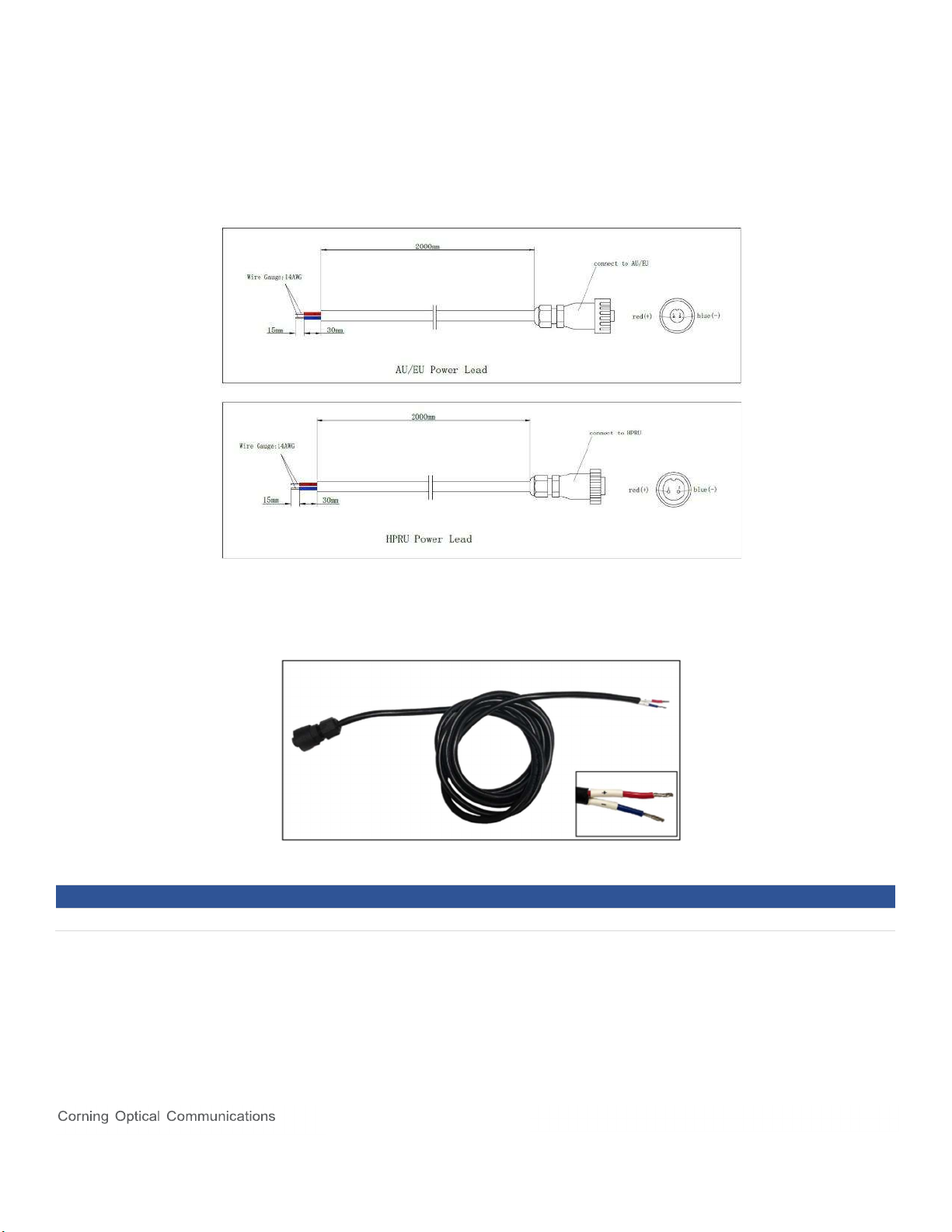
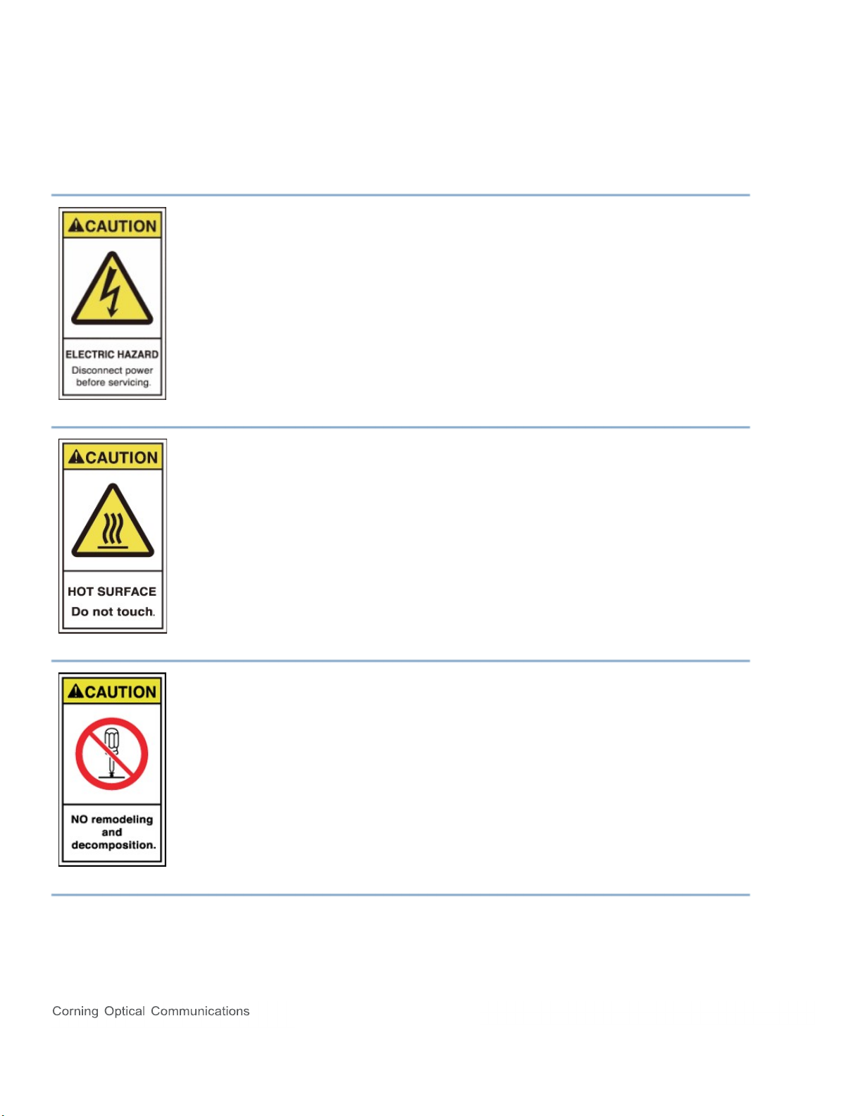
6. The power source must be within the required range of the device. The rated voltage range for the AC power supply
system is 100 ~ 240 VAC, and the rated frequency range is 50 Hz / 60 Hz. The rated power of the AU, EU, and
M2RU is 80 W, 50 W, and 150 W, respectively. The ground terminal of the three-core power socket used at the
device installation site must be securely connected to the protective building ground.
7. To avoid injuries or damage, use care, and obtain assistance before lifting any heavy system components or
equipment.
8. While fiber optic power levels used in this system are very low, it is advisable to avoid exposing the human eye to the
laser light emanating from a fiber port or plug.
9. Signals coupled from the BTS shall be no greater than +15 dBm, otherwise, the device will not operate normally, and
damage may occur to the circuit.
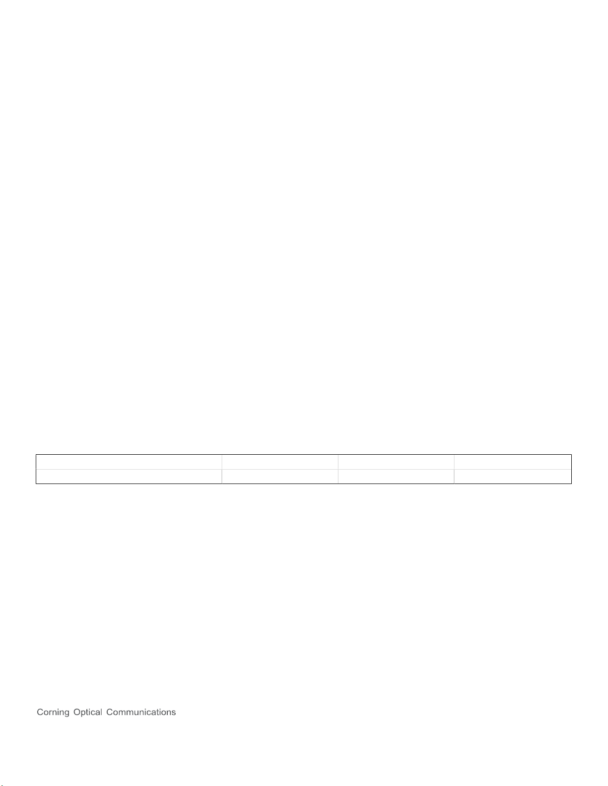
10. Reserve at least 40 mm of height above the radiation fins during device installation; otherwise, the device
temperature may rise and affect the service life of the device.
11. Follow Electro Static Discharge precautions to avoid any damage to PCB, PSU, etc.
12. Keep equipment powered-off during installing or modifying.
13. Low path loss cables connected to antennas are highly recommended.
14. This is NOT a CONSUMER device. It is designed for installation by FCC LICENSEES and QUALIFIED
INSTALLERS. You MUST have an FCC LICENSE or express consent of an FCC License to operate this device.
Unauthorized use may result in significant forfeiture penalties, including penalties in excess of $100,000 for each
continuing violation.
15. This is NOT a CONSUMER device. It is designed for installation by an installer approved by an ISED licensee. You
MUST have an ISED LICENCE or the express consent of an ISED licensee to operate this device.

Installation Manual | CMA-795-AEN | Page 5
16. To comply with FCC RF exposure compliance requirements, each individual antenna used for this transmitter must be
installed to provide a separation distance greater than 105 cm or more from all persons during normal operation and
must not be co-located with any other antenna for meeting RF exposure requirements.
17. In accordance with wireless service provider standards it is not advised to use digital repeaters as a signal source for
Corning solutions.
18. Antenna gain should not exceed 6 dBi.
Note: This device complies with Part 15 of the FCC Rules. Operation is subject to the following two conditions: (1) this
device may not cause harmful interference, and (2) this device must accept any interference received, including
interference that may cause undesired operation.
NOTE: This equipment has been tested and found to comply with the limits for a Class B digital device, pursuant to
Part 15 of the FCC Rules. These limits are designed to provide reasonable protection against harmful interference in a
residential installation. This equipment generates uses and can radiate radio frequency energy and, if not installed and
used in accordance with the instructions, may cause harmful interference to radio communications. However, there is
no guarantee that interference will not occur in a particular installation.
If this equipment does cause harmful interference to radio or television reception, which can be determined by turning
the equipment off and on, the user is encouraged to try to correct the interference by one or more of the following
measures:
-- Reorient or relocate the receiving antenna.
-- Increase the separation between the equipment and receiver.
-- Connect the equipment into an outlet on a circuit different from that to which the receiver is connected.
-- Consult the dealer or an experienced radio/TV technician for help.
Note: Only authorized person can enter the area where the antenna is installed. And the person is fully aware of the
potential for exposure and can exercise control over his or her exposure by leaving the area or by some other
appropriate means. Awareness of the potential for RF exposure in a workplace or similar environment can be provided
through specific training as part of a RF safety program
NOTE: This device complies with Industry Canada license-exempt RSS standard(s). Operation is subject to the
following two conditions: (1) this device may not cause interference, and (2) this device must accept any interference,
including interference that may cause undesired operation of the device.
Le présent appareil est conforme aux CNR d'Industrie Canada applicables aux appareils radio exempts de licence.
L'exploitation est autorisée aux deux conditions suivantes : (1) l'appareil ne doit pas produire de brouillage, et (2)
l'utilisateur de l'appareil doit accepter tout brouillage radioélectrique subi, même si le brouillage est susceptible d'en
compromettre le fonctionnement.

Installation Manual | CMA-795-AEN | Page 6
Site Considerations
1. Everon™ 6200 complies with FCC RF exposure limits for an uncontrolled environment.
2. The system delay should be taken into consideration when there are neighboring BTS sites that are overlapping in
coverage. Normal use of the system will not damage the base station; however, with the increase of RU during
network coverage for indoor distribution, the uplink output noise level may affect the sensitivity of the base station,
which should be considered during engineering design.
3. Pick an ideal easy-to-reach location for installation convenience.
4. Verify that there is a minimum of a 50 cm radius of space around Everon™ 6200 equipment for the convenience of
maintenance and on-site inspection.
5. Install Everon™ 6200 close to the service area for monitoring and debugging.
Environmental Considerations
Humidity and temperature can adversely affect reliability of the Everon™ 6200 system. Therefore, it is highly
recommended to install the equipment in locations with stable humidity, temperature, and ventilation.
The equipment must operate at the humidity and temperature ranges below:
Maximum humidity (M2RU): 100% (Non-Condensing)
Operating Temperature range (A2/EU): -10°C to +50°C
Operating Temperature range (M2RU): -40°C to +55°C
Storage Temperature range: -25°C to +70°C

Installation Manual | CMA-795-AEN | Page 7
DC Power Connections
Referring to the diagram, connect the power cables as follows:
Higher voltage wire linked to RED cable / Lower voltage wire linked to BLUE cable.
Connect “+” to a high potential (+48 VDC from a +48 VDC power supply; 0 VDC from a -48 VDC power supply)
Connect “-” to a low potential (0 VDC from a +48 VDC power supply; -48 VDC from a -48 VDC power supply)
Cable Core Cable Length Maximum Expandable Length
14 AWG 2 m 10 m

Installation Manual | CMA-795-AEN | Page 8
Warning Marks
The warning marks on the Everon™ 6200 shell should be kept clean, readable, and identifiable.
ALWAYS disconnect all lines and power connections before servicing or
disassembling this equipment.
NEVER touch the surface after the device's power is turned on.
For performance and safety reasons, NEVER disassemble and remodel the
devices.

Installation Manual | CMA-795-AEN | Page 9
Installation Preparation
Unpacking and Inspecting
This section discusses the procedures for receiving the shipment, inspecting the packing container, unpacking, and
inspecting the device.
Inspecting the Packing Container
Handle the packing container carefully. Inspect the packing container immediately on arrival at the installation site to
verify that no obvious damage occurred during shipment. Ensure that the container is sound and that the waterproof and
vibration warning notices are still obvious. If possible, always inspect the equipment in the presence of the delivery
person.
If any damage is observed:
1. Do not open or unpack the container.
2. Immediately contact the transportation carrier and notify them of the damage.
3. File a claim with the carrier once you determine the extent of any damage.
4. Return it to CORNING’s nearest RMA facility and contact CORNING for RMA processing.
Unpacking the Device
If the container appears to be in satisfactory condition:
1. Ensure both user and supplier representatives are in attendance during shipment inspection.
2. Confirm where you will store the device.
3. Ensure procedures are in place to handle the device and other equipment properly.
4. Ensure the following tools are available to unpack the shipment: hammer, paper cutter, and crowbar.
5. Open the packing container carefully. The device is contained in a protective package inside the packing container;
however, caution is still necessary so as not to damage the internal package and device.
6. Remove the internal package from the packing container.
7. Unpack the device from the internal package carefully.
Verifying the Contents
To verify the contents of the package:
1. Verify that the contents and quantities agree with the Delivery Packing List.
2. Check the device model against the Delivery Packing List.
3. Notify CORNING immediately if any discrepancies are discovered, to verify whether the complete and correct
shipment has been received.

Installation Manual | CMA-795-AEN | Page 10
Inspecting the Device
After unpacking the device, place the device on solid ground and check the following to ensure the device has not been
damaged:
1. Inspect the device’s appearance, overall dimensions, and weight.
2. Check that the device has not been deformed or bent in any way.
3. Check that there are no warps, scratches, bubbles, or dirt marks.
4. Check that there are no loose, missing or incorrectly fastened screws.
5. Check that the installation slots in the cabinet subrack are rectangular.
6. Ensure that the guide bar has not been damaged and the fittings and auxiliary parts are intact.
7. Check that the silk-screened images on the device are visible and intact.
Site Investigation
Before installation, the installer should contact the project director to ensure that the site is suitable for installation.
Details required include information about the installation site, such as whether there is an iron tower or high mast
nearby, the surrounding environmental conditions such as temperature and humidity, the power source, and so on.
Installation staff should complete a site investigation with the project director before construction and conduct field
observation of the installation site and the coverage area of the device, to confirm factors such as signal intensity, signal
quality, the required coverage range, device location, antenna-feeder system, and power supply system.
Note: Only maintenance personnel or users who understand the reason for access and are experienced with restricted
area access and understand the necessary preventive measures should access the installation site.
Installation Tools
The following equipment and tools are required for a successful installation:
Electric percussion drill / Screwdriver / Wrench
Torque Settings
Type M3 M6 M10
Specified Torques 0.6 nm 5 nm 50 nm
Clearance
You must ensure the following mounting clearances for mounting within a 19-inch rack/cabinet:
Fan Cooling:
You can mount the fan between the bottom of the device and any other.
Maintain 2U clearance between the bottom of the device and any other.
You must ensure the following mounting clearances for wall mounting:
Convection cooling:
Maintain 150mm clearance from the bottom of the device to any other planar obstructions.
Maintain 150mm clearance from the top of the device to any other planar.
Maintain 150mm clearance from both sides of the device to any other planar obstructions

Installation Manual | CMA-795-AEN | Page 11
Tools
Electric drill, crosshead screwdriver, side cutters, ladder, and other tools are needed for M2RU installation.
Customers are to provide these tools themselves.
Drilling Machine Pen Allen Wrench T5 Combination
Spanner 17 mm
Nut M10 and
M12

Installation Manual | CMA-795-AEN | Page 12
Installing the Access Unit (AU)
Accessories List

Installation Manual | CMA-795-AEN | Page 13
Rack Installation
The Access Unit is a 19-inch 1U equipment shelf. When installing the Access Unit in a rack, make sure the mechanical
loading of the rack is even to avoid a hazardous condition. The rack should safely support the combined weight of all the
equipment and be securely anchored. Installing the Access Unit in a climate-controlled room with sufficient air circulation
is recommended as the maximum ambient temperature is +50°C.
To install the Access Unit in the equipment rack.
1. Attach the 19-inch mounting brackets at the front of the AU, using 4 screws M3×6 per bracket and the Phillips
screwdriver. Observe the orientation of the brackets.
2. Recommended attaching the sliding rails to rack. (Not included in delivery).

Installation Manual | CMA-795-AEN | Page 14
3. Place the AU in the rack and secure the AU using 2 screws M6×16 on both side and the Phillips screwdriver.
4. Install the cooling fan if multiple AUs are installed in the same rack.
It is necessary to allow at least 3 rack units (132 mm) of free space below each unit for heat dissipation without fan installed or 1
rack unit (44 mm) of free space below each unit with fan occupied in the middle.
Otherwise, the device temperature may rise and affect the service life of the device.

Installation Manual | CMA-795-AEN | Page 15
5. Connect and lock the power cable at the AU rear side.
6. Connect and screw the ground wire at the AU rear side.

Installation Manual | CMA-795-AEN | Page 16
Fan Installation
1. Secure the fan using 2 screws M6×16 on both sides and the Phillips screwdriver
2. Plug AC power lead.

Installation Manual | CMA-795-AEN | Page 17
3. Fan DC version has power cable embedded in chassis.
Note: Red is for positive; black is for negative. There are labels at cable ends to distinguish positive or negative
pole.
Note: Connect “+” to a high potential (+48 VDC from a +48 VDC power supply; 0 VDC from a -48 VDC power
supply)
Note: Connect “-” to a low potential (0 VDC from a +48 VDC power supply; -48 VDC from a -48 VDC power supply)
Warning: The fan has no reverse polarity protection. Reverse connection will cause power supply damage.

Installation Manual | CMA-795-AEN | Page 18
Wall Installation
To install the Access Unit on the wall:
1. Rotate the handles 90°and attach them at the rear of the AU, using 4 screws M3×6 per bracket and the Phillips
screwdriver. Observe the orientation of the brackets.

Installation Manual | CMA-795-AEN | Page 19
2. Mark 4 x ∅6.8 mm drilling holes sites for the hanger to be attached to the wall.
3. Drill 4 holes at the marked sites using percussion drill and embed 4×10 plastic expansion pipes.
Note: H = 70 mm.
Fasten the case with 4×M6 expansion bolt.

Installation Manual | CMA-795-AEN | Page 20
4. Connect and lock the power cable at the AU rear side
5. Connect and screw the ground wire at the AU rear side
This manual suits for next models
2
Table of contents
Other CORNING Portable Generator manuals
Popular Portable Generator manuals by other brands

Pulsar
Pulsar G465GN Operator's manual

NORTHMARK
NORTHMARK YDE2800X/E user manual

Champion Power Equipment
Champion Power Equipment 40011 Owner's Manual and Operating Instructions

National Instruments
National Instruments NI 5401 Getting started guide

Westerbeke
Westerbeke 7.0BCG Operator's manual

National Instruments
National Instruments NI PXIe-5673E CALIBRATION PROCEDURE