CORRECT CRAFT LINC PAN0RAY 2020 User manual

LINC PAN0RAY
20 OWNER’S MANUAL
FOR SUPER AIR NAUTIQUE MODELS

LINC PAN0RAY
2
TABLE OF CONTENTS
OVERVIEW
Product Information
Care and Maintenance
Touchscreen Display
Helm Command
User Interface
t4QMJt Interface Mode
tGeneral Layout
tFullscreen Mode and Layout
Using Helm Command
tRotary Knob
t#Vtton 4IPrtcuts
HOME MENU
Main Tab
tG and G4#Pats
taOE#Pats
4tatus Tab
River Mode Tab
4teering Assist Tab (Optional)
AUDIO MENU
Main Tab
Dynamic4ource Tab
Zone Control Tab
"VEJP4etup Tab
GOPRO MENU
Control Tab
4ettings Tab
t$POOecting a GoPro Camera
Gallery Tab
BALLAST MENU
Manual Tab
4et Level Tab
Overhead Tab (witI#allast4IJGt)
5
5
6
7
9
10-11
13
14-19
20-25
26-33
26-29
30-33
34
35-37
38-41
42-43
44-45
46
47-48
50
51-55
52-55
56-57
58
59
60
P/N:

LINC PAN0RAY
3
SWITCHING MENU
Lights Tab
Courtesy Color Tab (Optional)
Climate Tab
Features Tab
USER MENU
User List Tab
New User Tab
MAP MENU
Mini Map Tab
Full Map Tab
•Waypoints and Tracks
PREFERENCES MENU
Settings Tab
Display Tab
System Tab
•Power Diagnostics
•Engine Diagnostics
•System Info
RIGHT SECTION
Switchboard Tab
•Editing the Functions
Vitals Tab
WARNINGS AND POP UP MESSAGE
Engine Diagnostic Message
Circuit Fault Message
62
63-65
66
67
68-69
70-71
72
73-75
74-75
76
77
78-81
79
80
81
82-85
83-85
86
88
89

LINC PAN0RAY
4

LINC PAN0RAY
5
OVERVIEW
PRODUCT INFORMATION
The Nautique LINC 3.0 system is designed for instrumentation and
control on electronically controlled engines communicating via SAE J1939
and NMEA 2000. The display is a multifunctional tool that provides GPS
tracking, multimedia display, speed control, and enables equipment
RSHUDWRUVWRYLHZPDQ\GLHUHQWHQJLQHSDUDPHWHUVDQGVHUYLFHFRGHV
CARE AND MAINTENANCE
General maintenance is not required; however, a soft cloth can be
used for cleaning the unit. Window cleaner or alcohol can also be used
to clean the glass portion of the display. Do not use harsh or abrasive
cleaners on the unit.

LINC PAN0RAY
6
OVERVIEW
TOUCHSCREEN DISPLAY
LINC Panoray features a 12.4” wide touchscreen display. Operators can
easily change settings and viewed information by tapping certain touch-
point icons on the screen. When the display recognizes that the operator
has touched the screen, a small, grey, circular graphic will appear at the
location where the operator has touched.
Operators can also scroll and swipe certain functions, lists and menus on
the touchscreen display.
7RHQVXUHSURSHUXVHPDNHVXUHWKDWKDQGVDQGȴQJHUVDUHGU\DQG
clean of any oils or lotions before touching the display.

LINC PAN0RAY
7
OVERVIEW
HELM COMMAND
In addition to the touchscreen, the LINC 3.0 interface can also be fully
controlled with the Helm Command (pictured above) located on the
driver’s armrest adjacent to the throttle arm.
Helm Command features a machined, aluminum knob. This knob is able
to 1) rotate clockwise and counterclockwise, 2) tilt up, down, left and right
like a joystick and 3) can be pressed down like a button. The functions of
each of the three physical actions listed above can change depending on
the particular menu that is displayed.
$EODFNUXEEHUNH\SDGVXUURXQGVWKHNQREZLWKGLHUHQWEXWWRQV
These buttons act like shortcuts, or hot keys, and allow the user to
quickly jump to certain menus, tabs and frequently used settings.
Please refer to the following pages for a step-by-step instruction on how
to use Nautique’s Helm Command with the user interface.

LINC PAN0RAY
8

LINC PAN0RAY
9
OVERVIEW
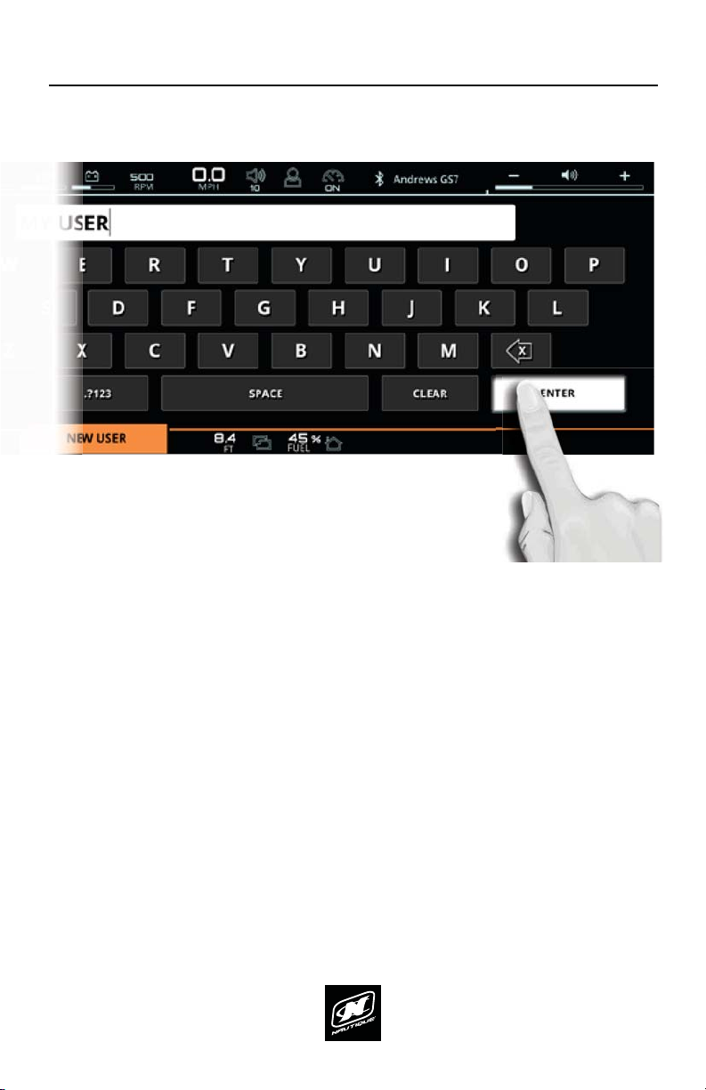
USER INTERFACE - SPLIT INTERFACE MODE
In most circumstances, the LINC Panoray interface is split into three, broad visual
sections; the center section, the left section and the right section.
CENTER SECTION - displays critical gauges, settings and functions (e.g. speed,
VSHHGFRQWURORQRWKDWFDQEHVHHQDWDJODQFHXQGHUPRVWVFHQDULRV
LEFT SECTIONGLVSOD\VVSHFLȴFGHWDLOHGLQIRUPDWLRQDQGIXQFWLRQVZKLFKLV
dictated mostly by the currently selected menu and menu tab. The operator
should use this section when he/she wants to take their time and get an “in-
depth” look into certain boat settings or features. For example, if an operator
wants to change individual audio settings, he/she should look at the left side of
the screen, navigate to the audio menu and select the proper menu tab to adjust
VSHFLȴFDXGLRVHWWLQJV
RIGHT SECTION - also displays information and functions, but is meant for
quicker operation. The right section does not use menus and contains only two
tabs at all times: the vitals tab and the switchboard tab. The vitals tab contains
YLWDOHQJLQHJDXJHVDQGLQIRUPDWLRQDQGWKHVZLWFKERDUGWDEFRQWDLQVGLHUHQW
functions that can be customized by the user (see pages 62-65). The switchboard
tab allows the operator to select his/her four favorite functions so that they
FDQEHTXLFNO\DGMXVWHGRUWXUQHGRQRIURPWKHULJKWVLGHZLWKRXWKDYLQJ
to navigate to any left side menus. Think of the switchboard tab as if it were
containing “shortcuts” to an operator’s most used/viewed features.
RIGHT SECTIONCENTER SECTIONLEFT SECTION

LINC PAN0RAY
10
OVERVIEW
USER INTERFACE - GENERAL LAYOUT
AREA FOR CRITICAL GAUGES & SETTINGS - This area displays the
FXUUHQWVSHHGVHWVSHHGVSHHGFRQWURORQRIXHOJDXJHDQGGHSWK
gauge. This area also duplicates the 5 buttons on the Helm Command.
UPPER STATUS BAR - This area always displays the activated User
3URȴOHWLPHHQJLQHWHPSHUDWXUHRLOSUHVVXUHYROWDJHDQG5307KH
operator can tap on the engine temperature, oil pressure, or voltage for
a numerical readout of that particular gauge. This area can also display
an icon for Surf Select if that setting is turned on.
MENU WHEEL 'LHUHQWPHQXVFDQEHVHOHFWHGKHUHE\WDSSLQJ
individual menu icons or by rotating the Helm Command knob if the
Menu Wheel is highlighted. There can be up to 8 menus: Home, Audio,
Video, Ballast, Switching, User, Map, and Preferences. The middle icon of
the Menu Wheel shows which menu is currently being viewed.
MENU TAB BAR - This tab bar changes depending on the current menu.
Each tab contains a separate page of information that relates back to the
current menu. Menus contain either 2, 3 or 4 unique tabs.
UPPER STATUS BAR AUDIO BAR
MENU TAB BAR RIGHT TAB BAR
MENU WHEEL
CURRENT SPEED & SET SPEED VOLUME LEVEL
FUEL GAUGE
VIEWING AREA OF
CURRENT MENU &
MENU TAB
(AKA “PAGE”)
VIEWING AREA OF
CURRENT RIGHT TAB*
AREA FOR CRITICAL GAUGES & SETTINGS
DEPTH GAUGE

LINC PAN0RAY
11
USER INTERFACE - GENERAL LAYOUT (CONTINUED)
VIEWING AREA OF CURRENT MENU & MENU TAB (AKA “PAGE”) -
Each tab under each menu displays unique information, settings, and
functions in this area (which can be referred to as a “page”). Most settings
and functions are illustrated here as a stack-up of smaller horizontal bars
with curved ends.
AUDIO BAR - This area always displays the current stereo source and the
volume level of the audio system. Tapping the + or the - on the volume
level will increase or decrease the volume. Tapping the volume horn icon
will mute or unmute the audio system.
RIGHT TAB BAR - This tab bar always features two tabs: the switchboard
tab and the vitals tab. The switchboard tab (shown in the screenshot)
features 4 functions that can be customized by a user (see pages 62-
65). The vitals tab displays all of the vital engine gauges and system
information for the boat in a large, easy to read format. This includes
engine temperature, engine oil pressure, battery charging voltage, engine
RPM, air temperature and water temperature. The vitals tab also includes
WKH6SHHG&RQWURO2Q2VRWKDWXVHUVFDQTXLFNO\WXUQWKDWRQRURDV
needed.
VIEWING AREA OF CURRENT RIGHT TAB - this area will display
information, settings, and functions from the switchboard tab or the
vitals tab, whichever is selected.
*NOTE: Certain menus and menu tabs from the left side may temporarily
occupy this space when there are more than 5 functions or settings.
OVERVIEW

LINC PAN0RAY
12

LINC PAN0RAY
13
USER INTERFACE - FULLSCREEN MODE AND LAYOUT
Some menus and menu tabs will adjust the appearance of the user interface in
order to increase the viewing area of certain features; these are called “fullscreen
pages”. Examples of full screen pages include the following:
Instances when a keyboard is required (e.g. when creating a new user)
Map Menu - Full Map tab
Preferences Menu - System tab, diagnostic pages and dealer menu pages
Full screen pages will slightly re-position critical gauges and settings to the top
and bottom of the screen. Current speed and volume level move to the top in
the FULLSCREEN STATUS BAR whereas the depth and fuel gauges move to the
bottom in the MENU TAB BAR.
FULLSCREEN STATUS BAR
CURRENT SPEED
FUEL GAUGEDEPTH GAUGE
VOLUME LEVEL
VIEWING AREA OF
FULLSCREEN PAGE
MENU TAB BAR
OVERVIEW

LINC PAN0RAY
14
OVERVIEW
LINC INTERFACE
FIG. A1 - ROTATING CLOCKWISE FROM THE HOME MENU TO THE MEDIA MENU
HELM COMMAND
USING HELM COMMAND - ROTARY KNOB
When LINC 3.0 has completed its start-up sequence, a “highlight” will appear
over the Menu Wheel. This highlight is similar to a computer cursor; it shows the
current position for user interaction and it will respond to input from the rotary
knob or the 5 buttons on the Helm Command unit. The highlight will stay in the
same location until it is moved to a new function/setting or until a new menu or
menu tab is selected.
When the highlight is over the Menu Wheel, simply rotate the Helm Command
NQREFORFNZLVHRUFRXQWHUFORFNZLVHWRYLHZDQRWKHUPHQXVHHȴJ$EHORZ

LINC PAN0RAY
15
OVERVIEW
To move the highlight to the page area of the screen (to the left side), the
operator can either press down on the knob or can joystick over to the left.
(See Fig. A3 below)
FIG. A2 - ROTATING COUNTER-CLOCKWISE BACK TO THE HOME MENU FROM THE MEDIA MENU
FIG. A3 - MOVING THE HIGHLIGHT TO THE PAGE AREA
PUSH
OR
USING HELM COMMAND - ROTARY KNOB (CONTINUED)
To return to a previously viewed menu, simply rotate the knob the opposite way.
The menu will appear with the tab that was last selected (see Fig. A2 below).

LINC PAN0RAY
16
OVERVIEW
When a setting is selected, simply rotate clockwise or counter-clockwise to
increase or decrease that setting. In Fig. A5 below, the operator has rotated
counter-clockwise twice to change the NSS Setting to “0”. When an ON/OFF
function (like NSS in Fig A5. below) is selected , rotate clockwise to tun ON or
rotate counter-clockwise to turn OFF.
USING HELM COMMAND - ROTARY KNOB (CONTINUED)
After moving the highlight to the page area, the operator can select functions/
settings by pushing down on the knob. (see Fig. D below). This will change the
background color behind the function/setting to white to increase visibility over
the other functions/settings.
FIG. A5 - ROTATING COUNTER-CLOCKWISE TO DECREASE A SETTING
FIG. A4 - PUSHING DOWN TO SELECT A SETTING (THE NSS SETTING IN THIS EXAMPLE)
PUSH

LINC PAN0RAY
17
OVERVIEW
USING HELM COMMAND - ROTARY KNOB (CONTINUED)
When the operator is comfortable with where the setting is at, he/she may push
down on the knob to de-select from the setting (see Fig, A6 below).
The operator may now rotate the knob to highlight another setting. In the image
below (Fig. A7) the operator has rotated counter-clockwise twice to highlight the
NCRS Setting
FIG. A6 - PUSHING DOWN TO DE-SELECT A SETTING (THE NSS SETTING IN THIS EXAMPLE)
FIG. A7 - ROTATING COUNTER-CLOCKWISE TO HIGHLIGHT A DIFFERENT SETTING
PUSH

LINC PAN0RAY
18
OVERVIEW
When a setting is selected, simply rotate clockwise or counter-clockwise to
increase or decrease that setting. In Fig. I below, the operator has rotated
clockwise twice to increase the NCRS Setting to “5”.
USING HELM COMMAND - ROTARY KNOB (CONTINUED)
Once again, an operator can select functions/settings by pushing down on the
knob; in Fig H. below the operator has selected the NCRS setting.
FIG. A9 - ROTATING CLOCKWISE TO INCREASE A SETTING
FIG. A8 - PUSHING DOWN TO SELECT A SETTING (THE NCRS SETTING IN THIS EXAMPLE)
PUSH

LINC PAN0RAY
19
OVERVIEW
USING HELM COMMAND - ROTARY KNOB (CONTINUED)
As mentioned previously, when the operator is comfortable with where the
setting is at, he/she may push down on the knob to de-select from that setting
(see Fig, J. below).
FIG. A10 - PUSHING DOWN TO DE-SELECT A SETTING (THE NCRS SETTING IN THIS EXAMPLE)
PUSH

LINC PAN0RAY
20
OVERVIEW
USING HELM COMMAND - BUTTON SHORTCUTS
$EODFNUXEEHUNH\SDGVXUURXQGVWKHNQREZLWKGLHUHQWEXWWRQV
These buttons act like shortcuts, or hot keys, and allow the user to
quickly jump to certain menus, tabs and frequently used settings.
The Volume, User and Speed Control buttons will each open up a unique
pop-up menu when pressed. Each of those pop-up menus will close
when that same button is pressed again.
HELM COMMAND
VOLUME
TAB
USER SPEED CONTROL
HOME
Table of contents
Popular Boating Equipment manuals by other brands

Scott Aerator
Scott Aerator De-Icer Dock Mount Aassembly Instructions

Mercury
Mercury 540 Bravo manual

Seakeeper
Seakeeper 35 GYRO Operation manual

Nexus
Nexus NX Sea Data Set TH43 Installation and operation manual

Seakeeper
Seakeeper 7000 GYRO Operation manual

Wichard
Wichard PROFURL MK 1R installation manual

Kobelt
Kobelt 7174 Owner's Operation, Installation & Maintenance Manual

Highfield
Highfield JC1200 installation guide

Vetus
Vetus HPW Installation and user manual

MAKE A WAKE MARINE
MAKE A WAKE MARINE Pro2 T-Top installation guide

Seakeeper
Seakeeper 26000 GYRO installation manual

OSCAR
OSCAR RACING Series installation guide