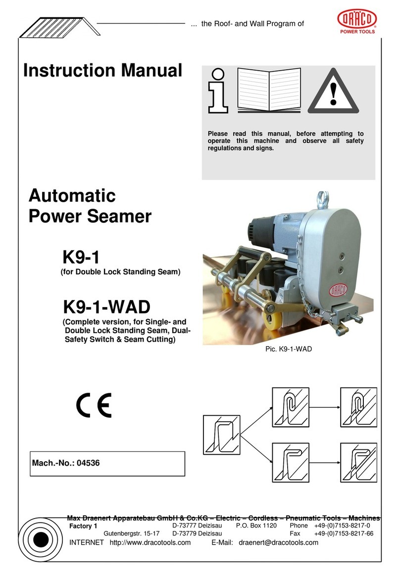
coval CVGL Series User manual

CVGL_Notice_COVAL_2021-V01.1_EN_FR
Retrouvez tous les documents en différentes langues sur le site coval : https://doc.coval.com/CVGL
Please find all the documents in different languages on the coval website: https://doc.coval.com/CVGL
Web : www.coval.com
Mail : coval@coval.com
Phone : +33 (0)4 75 59 91 91
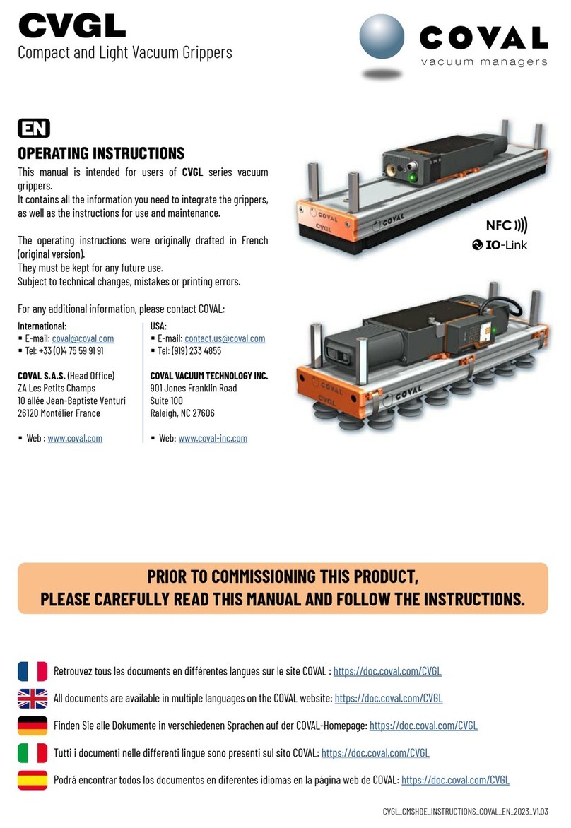
OPERATING INSTRUCTIONS
This manual is intended for users of carbon
vacuum grippers, CVGL series.
You will find the necessary information for the
integration of the grippers on the cobots, as
well as for their use and maintenance.
(pages 2-22)
For further information, please contact
COVAL:
INSTRUCTION DE SERVICE
Cette notice est destinée aux utilisateurs des
caissons à vide, série CVGL.
Vous y retrouverez les informations nécessaires
à l’intégration des caissons ainsi qu’à leur
utilisation et maintenance.
(pages 23-44)
Pour toutes informations complémentaires,
contactez la Sté COVAL :

NOTICE CVGL EN-FR (v01-2021)
page 2 sur 44
ZA des Petits-Champs
26120 Montélier.
France
SUMMARY:
1. IMPORTANT INFORMATION
2. INSTRUCTION FOR USE AND SAFETY
3. IDENTIFY YOU MODEL
4. OVERVIEW
5. FLOW CONTROL TECHNOLOGIES
6. DIMENSIONS AND MOUNTING OPTIONS
7. GRIPPING INTERFACES
8. SUPPLY AND PNEUMATIC CONNECTION
9. CVGL WITH VACUUM GENERATOR CONTROL
10. CVGL WITH VACUUM LEVEL DISPLAY
11. GENERAL CHARACTERISTICS
12. USE
13. MAINTENANCE
14. SPARE PARTS
15. RECYCLING
Operating Instructions
CVGL Series, Vacuum Grippers
PRIOR TO COMMISSIONING THIS PRODUCT,
PLEASE CAREFULLY READ THIS MANUAL AND FOLLOW
THE INSTRUCTIONS.

NOTICE CVGL EN-FR (v01-2021)
page 3 sur 44
ZA des Petits-Champs
26120 Montélier.
France
1. IMPORTANT INFORMATION
This document contains important instructions and information regarding the product’s various operational
phases:
. Transport, storage, commissioning and decommissioning
. Use and maintenance
The operating instructions correspond to the product actually delivered.
This document is part of the product and the following information must be observed:
. Please carefully read this document and observe the instructions to ensure safe installation, optimal
operation of the product and to avoid any malfunction
. Please keep the document within reach of the product so that the staff can easily access it.
Important:
. Failure to observe the instructions specified in this document may lead to injury or even death!
. COVAL will not be held liable for any damage or breakdown as a consequence of failure to observe
instructions.
For any additional information, please contact COVAL:
. Tel: +33 (0)4 75 59 91 91
2. INSTRUCTIONS FOR USE AND SAFETY
2.1. ASSEMBLY/DISASSEMBLY
Only qualified personnel is authorized to use the components. Such personnel must be trained in the following
areas:
. Applicable safety rules and requirements for using components and installing them in devices, machines and
machine lines
. Appropriate handling of components and their respective products
. Proper use with the operating materials
. The latest applicable EC directives, legislations, decrees and standards, as well as the current state of the art
The improper use of components with other operating materials than those defined, other voltages and under
other environmental conditions
can lead to failure, damage and injury.
This list is considered as an overview and does not claim to be exhaustive. Users can complement it
according to their particular needs.
2.2. SAFETY INSTRUCTIONS
In order to ensure flawless installation and operation, the following rules must also be observed:
. The components must be carefully removed from their packaging.
. The components must be protected against any and all damage.
. During installation and maintenance work, remove the voltage and pressure from the Venturi pump and
ensure that unauthorized personnel cannot restart it.
. Any attempt to alter the components is strictly prohibited.
. The area surrounding the components and the location where used must be kept clean.
. Standing under the payload being handled by the vacuum pump and in its pathway is strictly prohibited.
. Only the fittings/connectors provided may be used.
. During installation, only use flexible tubes and tubes that are suitable for the specific operating material
(tubes that come loose or electrical connection lines constitute a major safety hazard—including risk of
death!).
. Conductive and live cables lines must be insulated, of appropriate size, and properly installed.
. Pneumatic and electric lines must be connected to the component in a stable and safe manner.
. Prevent any physical contact with electric parts (protect electrical contacts).
. Only use the available fastening means described in section 6.5.
Operating Instructions
CVGL Series, Vacuum Grippers

NOTICE CVGL EN-FR (v01-2021)
page 4 sur 44
ZA des Petits-Champs
26120 Montélier.
France
. Always observe the latest applicable directives, regulations and standards as well as the current state of the
art for the suggested use.
. Wherever necessary, users must take specific measures to meet the requirements of applicable directives,
legislations, regulations and standards as well as the current state of the art.
2.3. NAMEPLATE
The nameplate is on the vacuum gripper so that it is legible at all times.
It includes the following information:
. Product ID
. Serial number
. Weight of the Vacuum Gripper
. CE Marking
Communicate the reference and the serial number of the product at the time of any exchange or requests with
our services.
Example :
NOTE:
This document details the operating instructions for the standard models, referenced in
chapter 3.
For specific models, marked SP XXX at the end of the article code on the nameplate, it is
necessary to adapt the information detailed in this document to the specificities of the
product.
The specific versions are products customized to meet the constraints of an application:
Example:
. Adaptation of the product length
. Multizone
. Other suction cups
. Other accessories
...
Operating Instructions
CVGL Series, Vacuum Grippers
Failure to observe the above safety instructions may lead to failure, damage, and
injury—even risk of death.
The components of the device that are no longer in working order must be recycled in
an environmentally-friendly manner (see section 15)!

NOTICE CVGL EN-FR (v01-2021)
page 5 sur 44
ZA des Petits-Champs
26120 Montélier.
France
3. INDENTIFY YOUR MODEL
Operating Instructions
CVGL Series, Vacuum Grippers

NOTICE CVGL EN-FR (v01-2021)
page 6 sur 44
ZA des Petits-Champs
26120 Montélier.
France
4. OVERVIEW
5. FLOW CONTROL TECHNOLOGIES
COVAL offers 3 flow control technologies to optimize your vacuum gripper and perfectly respond to the
constraints of your application.
Flow control nozzles
. Limits the leakage rate of
uncovered zones.
. Economic solution.
. Customizable calibration.
. Horizontal and vertical
handling.
Airtight valves (COVAL patent)
. Isolates uncovered zones.
. Provides energy savings.
. Meets specific needs.
. Instant gripping.
. Quick release to blow-off.
. Horizontal handling.
Check valves (COVAL patent)
. Limits the leakage rate of
uncovered zones.
. Instant gripping.
. High versatility of applications.
. Quick release to blow-off.
. Horizontal handling.
Operating Instructions
CVGL Series, Vacuum Grippers

NOTICE CVGL EN-FR (v01-2021)
page 7 sur 44
ZA des Petits-Champs
26120 Montélier.
France
6. DIMENSIONS AND MOUNTING OPTIONS
6.1 G0 Versions (with external vacuum generator)
6.2 E1 OR E2 VERSIONS (1 integrated vacuum generator, CMSL series).
6.3 E3 VERSION (2 integrated vacuum generators, CMSL series).
6.4 DIMENSIONS
The Coval CVGL series vacuum grippers version
G0 version (with external vacuum generator), can
be mounted on all types of automated or robotic
systems., via M8 spacers, sliding in the grooves of
the aluminium profile.
. CVGL 424 and 624 : 4 x M8 spacers.
. CVGL 824 : 8 x M8 spacers.
Permissible tightening torques :
. Spacers: 20 N m
The Coval CVGL series vacuum grippers,
E1 and E2 versions, are mounted on all
types of automated systems via M8 spacers
preinstalled on sliding nuts.
. CVGL 424 and 624 : 4 x M8 spacers.
. CVGL 824 : 8 x M8 spacers.
Permissible tightening torques :
. Spacers: 20 N m
. G1/4'' pressure connection: 10 N m
The CVGL vacuum grippers, E3
version, utilizes adjustable M8
spacers.
. CVGL 824 : 6 x M8 spacers.
Permissible tightening torques :
. Spacers: 20 N m
Operating Instructions
CVGL Series, Vacuum Grippers

NOTICE CVGL EN-FR (v01-2021)
page 8 sur 44
ZA des Petits-Champs
26120 Montélier.
France
7. GRIPPING INTERACES
Suction Cup Gripping Interface
Foam Gripping Interface
"COVAL-flex" Gripping Interface
Operating Instructions
CVGL Series, Vacuum Grippers

NOTICE CVGL EN-FR (v01-2021)
page 9 sur 44
ZA des Petits-Champs
26120 Montélier.
France
8. SUPPLY AND PNEUMATIC CONNECTION
8.1 Pneumatic supply for Vacuum Grippers equipped with one or more CMSL vacuum
generators (CVGL Version E1 - E2 and E3)
(Note: For CVGL vacuum gripper without vacuum generator (version G0), see the paragraph "connection of an
external vacuum source").
Pneumatic supply characteristics
•5μfiltered, non-lubricated air relevant to standard ISO 8573-1:2010 [4:5:4].
•Operating pressure : from 5 to 7 bar
•Optimum dynamic pressure : 6 Bar
•1 supply for generator type E1 and E2 (G1/4"-F connection).
•2 power supplies for generator type E3 (G1/4"-F connections).
Technical data of the CMSL series integrated vacuum generators
Vacuum generato
Model
Consumption
(Nl/min)
Flow rate
(Nl/min)
Max.
vacuum(%)
Sound level
(dBA)
CMSL90X50_
CVGL _ _ _ E1
190
900
85
65
CMSL90X100_
CVGL _ _ _ E2
380
1800
85
65
2xCMSL90X100_
CVGL _ _ _ E3
760
3600
85
65
8.2 Pneumatic connection
8.2.1 CVGL, E1 and E2 versions :
Connect the compressed air to the G1/4" connection on the multi-stage vacuum generator Series CMSL.
Version E1/E2 => Ø6 mm inner hose for length < 3 m. Ø8 mm hose for longer length
Version E3 => Ø8 mm inner tube for length < 3 m. Ø10 mm hose for longer length
Version N :
Without vacuum generator control
S or V versions:
With vacuum generator control
G1/4‘‘-F
G1/4‘‘-F
Operating Instructions
CVGL Series, Vacuum Grippers

NOTICE CVGL EN-FR (v01-2021)
page 10 sur 44
ZA des Petits-Champs
26120 Montélier.
France
8.2.2 CVGL, E3 version:
Connect the compressed air to the 2 G1/4 '' fittings located on the Multi-stage vacuum generators Series
CMSL.
8.2.3 CVGL, G0 version :
Connecting an external vacuum source :
To allow the connection of an external vacuum source, the CVG vacuum housings, G0 version, are equipped
with a threaded flange in G 1''-F. (positioning : see chapter 6 - Dimensions)
Note: Ø of the supply pipes to be adapted according to the flow rate of the external vacuum generator.
8.3 Vacuum switch connection :
To allow the connection of an external vacuum switch,
the CVGL vacuum boxes are equipped with a G1/8''-F connection.
Version N :
Without vacuum generator control
S or V versions:
With vacuum generator control
G1/4‘‘-F
G1/4‘‘-F
G1/4‘‘-F
G1/4‘‘-F
G1‘‘-F
Operating Instructions
CVGL Series, Vacuum Grippers

NOTICE CVGL EN-FR (v01-2021)
page 11 sur 44
ZA des Petits-Champs
26120 Montélier.
France
9. CVGL WITH VACUUM GENERATOR CONTROL (S and V versions)
When necessary, the CVGL series vacuum grippers with
Integrated vacuum generator (versions E1 and E2) can be
equipped with a vacuum and/or blow-off control valve to optimize
product release. This also enables cleaning of the vacuum
network, flow control nozzles, check valves or airtight valves.
A vacuum switch or analog gauge is available as an option for
those requiring a visual display of the vacuum level in the system
(see below).
10. CVGL WITH VACUUM LEVEL DISPLAY
(VA and VF versions)
When required, CVGL series grippers can incorporate a vacuum level display with an electronic vacuum
switch or vacuum gauge::
Operating Instructions
CVGL Series, Vacuum Grippers

NOTICE CVGL EN-FR (v01-2021)
page 12 sur 44
ZA des Petits-Champs
26120 Montélier.
France
11. GENERAL CHARACTRISTICS
•Compressed air supply for CVGL vacuum grippers with generator CMSL:
o5μfiltered, non-lubricated air relevant to standard ISO 8573-1:2010 [4:5:4].
o1 supply for generator type E1 and E2 (G1/4"-F pressure connection).
o2 supplies for generator type E3 (G1/4"-F pressure connection).
oOptimal working pressure: 6 bar (maximum pressure 8 bar).
•Blow-off: network supply pressure.
•Protection of the valve: IP 65.
•Temperature: 10 to 60°C.
•Material of the gripper: aluminium, PA 6.6 15% GF, brass, stainless steel, neoprene.
•Material of the valve: PA 6.6 15% GF, POM, PC 15% GF, brass, aluminium, NBR.
•Foam gripping interface material: EPDM.
•Suction cup gripping interface materials:
o"mini" type interface: silicone 30 Shore.
o"medium" type interfaces: natural rubber 50 Shore.
o"maxi" type interfaces: natural rubber 50 Shore or white silicone 35 Shore.
12. USE:
12.1 FOAM GRIPPING INTERFACE VERSION
Préconisation
•Operating temperature: from -40 to 180° C (from -40 to 356° F)
•Avoid prominent shapes
•Attention: angle of attack and robot stroke.
•Cover 50% of the surface of the foam gripper interface.
•Position of the gripper:
oAlways position the gripper in the centre of the load to manipulate.
oCVGL vacuum grippers are designed for the handling of loads in horizontal movement.
•It is not recommended to use the CVGC for vertical gripping as the foam could deteriorate quickly.
oIn the rare case of vertical use, tests should be performed prior to commercial use
oCOVAL will not be held responsible for the premature degradation of the foam.
Operating Instructions
CVGL Series, Vacuum Grippers

NOTICE CVGL EN-FR (v01-2021)
page 13 sur 44
ZA des Petits-Champs
26120 Montélier.
France
12.1.1 FOAM VERSION WITH FLOW CONTROL TECHNOLOGY BY VALVES:
Models CVGL_E (Airtight valves) and CVGL_V (Check valves) :
The steps of a working cycle of a CVGL vacuum gripper:
1. Position the vacuum gripper on the object to be handled with the foam grip interface parallel
to the surface of the object and compress the foam slightly.
2. Place the vacuum gripper on the object
3. Activate the vacuum
4. Manipulate the object
5. Deposit the object by stopping the vacuum and blowing if necessary.
Note: If the vacuum is activated before the vacuum gripper is in contact with the workpiece, the
workpiece will not be vacuumed because the check valves will be closed and will not allow gripping.
•The CVGL vacuum gripper with valves is designed for horizontal use.
Permitted inclination: 45° max.
The use of the vacuum gripper at 180° or 90° is not allowed.
•It is forbidden to stop or to cross the working area of the empty
gripper. In the event of an electrical or pneumatic power failure, the
load handled by the gripper is released.
•The maximum vertical acceleration allowed is 5 m / s² (16 ft / s²).
•Caution: When check or airtight valves are used in the vacuum
gripper, the vacuum value measured by the vacuum switch cannot be
used as a reliable indication of the object's grip. The vacuum switch
indicates the vacuum level inside the gripper, and due to the action of
the valves (closing of the valves), the vacuum level will be high even
when the object is not present
Operating Instructions
CVGL Series, Vacuum Grippers

NOTICE CVGL EN-FR (v01-2021)
page 14 sur 44
ZA des Petits-Champs
26120 Montélier.
France
12.1.2 FOAM VERSION WITH FLOW CONTROL TECHNOLOGY BY FLOW CONTROL NOZZLE:
Model CVGL_H (Flow controle nozzle):
The steps of a working cycle of a CVGL vacuum gripper:
1. Position the vacuum gripper box on the object to be handled with the foam grip interface
parallel to the object surface.
2. Place the vacuum gripper on the object and slightly compress the foam.
3. Activate the vacuum
4. Manipulate the object
5. Deposit the object by stopping the vacuum and blowing if necessary.
Note: In this case, the vacuum activation can be done before or after the contact with the part.
•It is forbidden to stop or to cross the working area of the gripper when
empty. In the event of an electrical or pneumatic power failure, the
load handled by the gripper is released.
•With the flow controle nozzle, the vacuum level measured by the
vacuum switch in the gripper is the actual vacuum present at the
object. In this case, the vacuum switch can be used to check the grip
of the object.
•Attention: Please note that the vacuum level is influenced by the
degree of coverage of the vacuum gripper on the object, as well as
the porosity of the object to be handled.
Note:
Handling the vacuum gripper in an upright position may cause the grip foam to shear. Depending on the
weight and/or center of gravity of the load, the foam may deteriorate rapidly. We recommend that you
always perform preliminary tests with original samples of the objects to be handled.
Contact the COVAL team to perform validation tests if necessary.
Operating Instructions
CVGL Series, Vacuum Grippers

NOTICE CVGL EN-FR (v01-2021)
page 15 sur 44
ZA des Petits-Champs
26120 Montélier.
France
12.2 SUCTION CUPS INTERFACE VERSION :
•Operating temperature: Depending on the material of the suction cups used.
•Avoid prominent shapes
•Attention: angle of attack and robot stroke.
The steps of a working cycle of a CVGL vacuum gripper:
1. Position the vacuum gripper on the object to be handled with the foam grip interface parallel
to the object surface.
2. Bring the vacuum gripper into contact with the object
3. Activate the vacuum
4. Manipulate the object
5. Deposit the object by stopping the vacuum and blowing if necessary.
Note: In this case, the vacuum activation can be done before or after the contact with the part.
•It is forbidden to stop or to cross the working area of the gripper when
empty. In the event of an electrical or pneumatic power failure, the load
handled by the chamber is released.
•With the flow controle nozzle, the vacuum level measured by the
vacuum switch in the vacuum gripper is the actual vacuum present at
the object. In this case, the vacuum switch can be used to check the
grip of the object.
•Attention: Please note that the vacuum level is influenced by the
degree of coverage of the vacuum gripper on the object, as well as the
porosity of the object to be handled.
Note: We recommend that you always perform preliminary tests with original samples of the objects to
be handled.
Contact the COVAL team to perform validation tests if necessary.
Operating Instructions
CVGL Series, Vacuum Grippers

NOTICE CVGL EN-FR (v01-2021)
page 16 sur 44
ZA des Petits-Champs
26120 Montélier.
France
13. MAINTENANCE :
13.1 FREQUENCY :
Determination of the maintenance frequency according to the rates,the environment and the type of load.
=> To be defined by the user.
13.2 ASSEMBLY / DISASSEMBLY OF GRIPPING INTERFACE:
2 possibilities for maintenance:
Replacement of only the foam or suction cups or replacement of the complete gripping interface.
Removal of the interface:
2 mounting versions available:
Screwed gripping interface:
The interface are screwed to the aluminium profile of the vacuum gripper.
Note: for vacuum gripper with foam, it is necessary to remove the foam to access the screws.
Clip-on gripping interface:
CVGL version _ _ _ C
Solution for quick assembly/disassembly of the gripping interface, with spring blade clips.
Number of clips according to the length of the vacuum gripper:
•CVGL424 : 6 clips
•CVGL624 : 8 clips
•CVGL824 : 10 clips
13.3 PROCEDURE FOR REPLACING THE GRIPPING FOAM :
1. Manually remove the used FOAM
interface.
2. Clean the plate with a chemical degreaser
(e.g.NECTRAL) to remove unwanted
compounds (adhesive residue, grease...).
3. On the replacement foam, rub the
protective film on the adhesive side for a
few seconds to activate the cells and
promote bonding.
4. Remove the protective film.
Operating Instructions
CVGL Series, Vacuum Grippers

NOTICE CVGL EN-FR (v01-2021)
page 17 sur 44
ZA des Petits-Champs
26120 Montélier.
France
13.4 SUCTION CUP REPLACEMENT PROCEDURE:
The suction cups are mounted on barbed fitting. Simply pull the suction
cup to replace it.
Tip for mounting the suction cups:
Soak the suction up neck in lukewarm water to facilitate the mounting on
the fitting.
13.5 DISMANTLING VACUUM GENERATOR PROCEDURE, CMSL Series:
13.6 VACUUM GRIPPER AIRTIGHT LEAK TEST
To ensure the proper functioning of the CVGL vacuum grippers after a maintenance operation, it is important
to complete an airtight leak test:
1. Place the gripper on a clean, smooth, flat and waterproof surface.
2. Activate vacuum.
3. Check the vacuum level on the electronic vacuum switch. It must be at least 80% (-800 mbar) at the optimal
functioning pressure of the housing.
If the vacuum level is not reached, check:
•the quality of the test surface,
•the wear of the gripping foam and its adhesive
•the size of the compressed air hose (depending on the configuration, see Chap. 8.2)
•the quality of the compressed air network (connections, pipes, leaks or damage) and replace defective
components.
•the pressure of the compressed air network:
− Optimal functioning pressure: 6 bar
5. Adhere foam to carbon plate by aligning the
holes.
6. Turn the gripper over and place it on a flat,
smooth and clean surface. Press lightly on the
box for 30 seconds so that the foam is uniformly
glued to the plate.
1. Unscrew the 4 CHC M4X8 screws to remove the
CMSL from the aluminum profile.
(Note: take care of the seal).
2. Replace the CMSL (see reference chapter 14.3)
3. Make sure to position the seal in its housing on the
CMSL mounting plate.
4. Position the CMSL with the vacuum port of the
CMSL centered in front of the vacuum supply port
of the aluminum profile.
5. Screw in the 4 CHC M4X8 screws
(tightening torque 2.5 N m)
CMSL90X__
4 x CHC M4X8
Operating Instructions
CVGL Series, Vacuum Grippers

NOTICE CVGL EN-FR (v01-2021)
page 18 sur 44
ZA des Petits-Champs
26120 Montélier.
France
14. SPARE PARTS :
14.1 FOAM GRIPPING INTERFACE:
14.1.1 Complete replacement foam gripping interface
Complete gripping interface for CVGL “Mini”type Foam
Complete interface for CVGL “mini”type foam with flow control nozzles (CVGL __QF2S H_)
Item code
Designation
CPL424QF2SXH
Complete interface for CVGL424QF2SXH (Foam dimensions 420 x 118 mm, with Ø12 mm holes without filter)
CPL624QF2SXH
Complete interface for CVGL624QF2SXH (Foam dimensions 620 x 118 mm, with Ø12 mm holes without filter)
CPL824QF2SXH
Complete interface for CVGL824QF2SXH (Foam dimensions 820 x 118 mm, with Ø12 mm holes without filter)
CPL424QF2SFH
Complete interface for CVGL424QF2SFH (Foam dimensions 420 x 118 mm, with Ø12 mm holes with filter)
CPL624QF2SFH
Complete interface for CVGL624QF2SFH (Foam dimensions 620 x 118 mm, with Ø12 mm holes with filter)
CPL824QF2SFH
Complete interface for CVGL824QF2SFH (Foam dimensions 820 x 118 mm, with Ø12 mm holes with filter)
Complete interface for CVGL “mini”type foam with Airtight valves (CVGL __QF2S E_)
Item code
Designation
CPL424QF2SXE
Complete interface for CVGL424QF2SXE (Foam dimensions 420 x 118 mm, with Ø12 mm holes without filter)
CPL624QF2SXE
Complete interface for CVGL624QF2SXE (Foam dimensions 620 x 118 mm, with Ø12 mm holes without filter)
CPL824QF2SXE
Complete interface for CVGL824QF2SXE (Foam dimensions 820 x 118 mm, with Ø12 mm holes without filter)
CPL424QF2SFE
Complete interface for CVGL424QF2SFE (Foam dimensions 420 x 118 mm, with Ø12 mm holes with filter)
CPL624QF2SFE
Complete interface for CVGL624QF2SFE (Foam dimensions 620 x 118 mm, with Ø12 mm holes with filter)
CPL824QF2SFE
Complete interface for CVGL824QF2SFE (Foam dimensions 820 x 118 mm, with Ø12 mm holes with filter)
Complete interface for CVGL “mini”type foam with Check valves (CVGL __QF2S V_)
Item code
Designation
CPL424QF2SXV
Complete interface for CVGL424QF2SXV (Foam dimensions 420 x 118 mm, with Ø12 mm holes without filter)
CPL624QF2SXV
Complete interface for CVGL624QF2SXV (Foam dimensions 620 x 118 mm, with Ø12 mm holes without filter)
CPL824QF2SXV
Complete interface for CVGL824QF2SXV (Foam dimensions 820 x 118 mm, with Ø12 mm holes without filter)
CPL424QF2SFV
Complete interface for CVGL424QF2SFV (Foam dimensions 420 x 118 mm, with Ø12 mm holes with filter)
CPL624QF2SFV
Complete interface for CVGL624QF2SFV (Foam dimensions 620 x 118 mm, with Ø12 mm holes with filter)
CPL824QF2SFV
Complete interface for CVGL824QF2SFV (Foam dimensions 820 x 118 mm, with Ø12 mm holes with filter)
Complete gripping interface for CVGL “Maxi”type Foam
Complete interface for CVGL “Maxi”type foam with flow control nozzles (CVGL __QF2B H_)
Item code
Designation
CPL424QF2BXH
Complete interface for CVGL424QF2BXH (Foam dimensions 420 x 118 mm, avec trous Ø16 mm sans filtre)
CPL624QF2BXH
Complete interface for CVGL624QF2BXH (Foam dimensions 620 x 118 mm, avec trous Ø16 mm sans filtre)
CPL824QF2BXH
Complete interface for CVGL824QF2BXH (Foam dimensions 820 x 118 mm, avec trous Ø16 mm sans filtre)
CPL424QF2BFH
Complete interface for CVGL424QF2BFH (Foam dimensions 420 x 118 mm, avec trous Ø16 mm avec filtre)
CPL624QF2BFH
Complete interface for CVGL624QF2BFH (Foam dimensions 620 x 118 mm, avec trous Ø16 mm avec filtre)
CPL824QF2BFH
Complete interface for CVGL824QF2BFH (Foam dimensions 820 x 118 mm, avec trous Ø16 mm avec filtre)
Complete interface for CVGL “Maxi”type foam with Airtight valves (CVGL __QF2B E_)
Item code
Designation
CPL424QF2BXE
Complete interface for CVGL424QF2BXE (Foam dimensions 420 x 118 mm, avec trous Ø16 mm sans filtre)
CPL624QF2BXE
Complete interface for CVGL624QF2BXE (Foam dimensions 620 x 118 mm, avec trous Ø16 mm sans filtre)
CPL824QF2BXE
Complete interface for CVGL824QF2BXE (Foam dimensions 820 x 118 mm, avec trous Ø16 mm sans filtre)
CPL424QF2BFE
Complete interface for CVGL424QF2BFE (Foam dimensions 420 x 118 mm, avec trous Ø16 mm avec filtre)
CPL624QF2BFE
Complete interface for CVGL624QF2BFE (Foam dimensions 620 x 118 mm, avec trous Ø16 mm avec filtre)
CPL824QF2BFE
Complete interface for CVGL824QF2BFE (Foam dimensions 820 x 118 mm, avec trous Ø16 mm avec filtre)
Complete interface for CVGL “Maxi”type foam with Check valves (CVGL __QF2B V_)
Item code
Designation
CPL424QF2BXV
Complete interface for CVGL424QF2BXV (Foam dimensions 420 x 118 mm, avec trous Ø16 mm sans filtre)
CPL624QF2BXV
Complete interface for CVGL624QF2BXV (Foam dimensions 620 x 118 mm, avec trous Ø16 mm sans filtre)
CPL824QF2BXV
Complete interface for CVGL824QF2BXV (Foam dimensions 820 x 118 mm, avec trous Ø16 mm sans filtre)
CPL424QF2BFV
Complete interface for CVGL424QF2BFV (Foam dimensions 420 x 118 mm, avec trous Ø16 mm avec filtre)
CPL624QF2BFV
Complete interface for CVGL624QF2BFV (Foam dimensions 620 x 118 mm, avec trous Ø16 mm avec filtre)
CPL824QF2BFV
Complete interface for CVGL824QF2BFV (Foam dimensions 820 x 118 mm, avec trous Ø16 mm avec filtre)
Operating Instructions
CVGL Series, Vacuum Grippers

NOTICE CVGL EN-FR (v01-2021)
page 19 sur 44
ZA des Petits-Champs
26120 Montélier.
France
14.1.2 Replacement Foam Soles
Foam soles for CVGL “mini”type foam (CVGL __QF2S _)
Item code
For model
Designation
80004220
CVGL424QF2SX_
Foam sole forCVGL424QF2SX (Foam dimensions 420 x 118 mm, with Ø12 mm holes without
filter)
80004221
CVGL624QF2SX_
Foam sole forCVGL624QF2SX (Foam dimensions 620 x 118 mm, with Ø12 mm holes without
filter)
80004222
CVGL824QF2SX_
Foam sole forCVGL824QF2SX (Foam dimensions 820 x 118 mm, with Ø12 mm holes without
filter)
80004223
CVGL424QF2SF_
Foam sole forCVGL424QF2SF (Foam dimensions 420 x 118 mm, with Ø12 mm holes with
filter)
80004224
CVGL624QF2SF_
Foam sole forCVGL624QF2SF (Foam dimensions 620 x 118 mm, with Ø12 mm holes with
filter)
80004225
CVGL824QF2SF_
Foam sole forCVGL824QF2SF (Foam dimensions 820 x 118 mm, with Ø12 mm holes with
filter)
Foam soles for CVGL “Maxi”type foam (CVGL __QF2B _)
Item code
For model
Designation
80004229
CVGL424QF2BX_
Foam sole forCVGL424QF2BX (Foam dimensions 420 x 118 mm, with Ø16 mm holes without
filter)
80004230
CVGL624QF2BX_
Foam sole forCVGL624QF2BX (Foam dimensions 620 x 118 mm, with Ø16 mm holes without
filter)
80004231
CVGL824QF2BX_
Foam sole forCVGL824QF2BX (Foam dimensions 820 x 118 mm, with Ø16 mm holes without
filter)
80004232
CVGL424QF2BF_
Foam sole forCVGL424QF2BF (Foam dimensions 420 x 118 mm, with Ø16 mm holes with
filter)
80004233
CVGL624QF2BF_
Foam sole forCVGL624QF2BF (Foam dimensions 620 x 118 mm, with Ø16 mm holes with
filter)
80004234
CVGL824QF2BF_
Foam sole forCVGL824QF2BF (Foam dimensions 820 x 118 mm, with Ø12 mm holes with
filter)
14.2 SUCTION CUPS GRIPPING INTERFACES:
14.2.1 Complete replacement suction cups gripping interface
Complete interface length 424 mm for CVGL424____
Screwed mounting
Item code
Designation
CPL424QVSP14BFXHX
Complete interface for CVGL424QVSP14BFXHX («mini» type gripping interface, staggered layout, 2.5
bellows suction cups Ø 14 mm silicone 30 shore with Flow control nozzles, screw mounting)
CPL424QVSA25JIXHX
Complete interface for CVGL424QVSA25JIXHX («medium» type gripping interface,staggered layout, 1.5
bellows suction cups Ø 25 mm Natural rubber with Flow control nozzles, screw mounting)
CPL424QVSA33JKXHX
Complete interface for CVGL424QVSA33JKXHX («Maxi» type gripping interface, staggered layout, 1.5
bellows suction cups Ø 33 mm Natural rubber with Flow control nozzles, screw mounting)
CPL424QMVS30EKXHX
Complete interface for CVGL424QMVS30EKXH («Maxi» type gripping interface staggered layout, 2.5
bellows suction cups Ø 30 mm silicone blanc 35 Shore with Flow control nozzles, screw mounting)
CPL424DVSA33JKXH
Complete interface for CVGL424DVSA33JKXH(«Maxi» type gripping interface straight layout, 1.5
bellows suction cups Ø 33 mm Natural rubber with Flow control nozzles, screw mounting)
Clipped Mounting
Item code
Designation
CPL424QVSP14BFXHC
Complete interface for CVGL424QVSP14BFXHC («mini» type gripping interface, staggered layout, 2.5
bellows suction cups Ø 14 mm silicone 30 shore with Flow control nozzles, clipped mouting)
CPL424QVSA25JIXHC
Complete interface for CVGL424QVSA25JIXHC («medium» type gripping interface, staggered layout, 1.5
bellows suction cups Ø 25 mm Natural rubber with Flow control nozzles, clipped mouting)
CPL424QVSA33JKXHC
Complete interface for CVGL424QVSA33JKXHX («Maxi» type gripping interface staggered layout, 1.5
bellows suction cups Ø 33 mm Natural rubber with Flow control nozzles, clipped mouting)
CPL424QMVS30EKXHC
Complete interface for CVGL424QMVS30EKXH («Maxi» type gripping interface staggered layout, 2.5
bellows suction cups Ø 30 mm silicone blanc 35 Shore with Flow control nozzles, clipped mouting)
CPL424DVSA33JKXC
Complete interface for CVGL424DVSA33JKXH(«Maxi» type gripping interface straight layout, 1.5
bellows suction cups Ø 33 mm Natural rubber with Flow control nozzles, clipped mouting)
Operating Instructions
CVGL Series, Vacuum Grippers

NOTICE CVGL EN-FR (v01-2021)
page 20 sur 44
ZA des Petits-Champs
26120 Montélier.
France
Complete interface length 624 mm for CVGL624____
Screw mounting
Item code
Designation
CPL624QVSP14BFXHX
Complete interface for CVGL624QVSP14BFXHX («mini» type gripping interface, staggered layout, 2.5
bellows suction cups Ø 14 mm silicone 30 shore with Flow control nozzles, screw mounting)
CPL624QVSA25JIXHX
Complete interface for CVGL624QVSA25JIXHX («medium» type gripping interfacestaggered layout, 1.5
bellows suction cups Ø 25 mm Natural rubber with Flow control nozzles, screw mounting)
CPL624QVSA33JKXHX
Complete interface for CVGL624QVSA33JKXHX («Maxi» type gripping interface staggered layout, 1.5
bellows suction cups Ø 33 mm Natural rubber with Flow control nozzles, screw mounting)
CPL624QMVS30EKXHX
Complete interface for CVGL624QMVS30EKXH («Maxi» type gripping interface staggered layout, 2.5
bellows suction cups Ø 30 mm silicone blanc 35 Shore with Flow control nozzles, screw mounting)
CPL624DVSA33JKXH
Complete interface for CVGL624DVSA33JKXH(«Maxi» type gripping interface straight layout, 1.5
bellows suction cups Ø 33 mm Natural rubber with Flow control nozzles, screw mounting)
Clipped mouting
Item code
Designation
CPL624QVSP14BFXHC
Complete interface for CVGL624QVSP14BFXHC («mini» type gripping interface, staggered layout, 2.5
bellows suction cups Ø 14 mm silicone 30 shore with Flow control nozzles, clipped mouting)
CPL624QVSA25JIXHC
Complete interface for CVGL624QVSA25JIXHC («medium» type gripping interfacestaggered layout, 1.5
bellows suction cups Ø 25 mm Natural rubber with Flow control nozzles, clipped mouting)
CPL624QVSA33JKXHC
Complete interface for CVGL624QVSA33JKXHX («Maxi» type gripping interface staggered layout, 1.5
bellows suction cups Ø 33 mm Natural rubber with Flow control nozzles, clipped mouting)
CPL624QMVS30EKXHC
Complete interface for CVGL624QMVS30EKXH («Maxi» type gripping interface staggered layout, 2.5
bellows suction cups Ø 30 mm silicone blanc 35 Shore with Flow control nozzles, clipped mouting)
CPL624DVSA33JKXC
Complete interface for CVGL624DVSA33JKXH(«Maxi» type gripping interface straight layout, 1.5
bellows suction cups Ø 33 mm Natural rubber with Flow control nozzles, clipped mouting)
Complete interface length 824 mm for CVGL824____
Screw mounting
Item code
Designation
CPL824QVSP14BFXHX
Complete interface for CVGL824QVSP14BFXHX («mini» type gripping interface, staggered layout, 2.5
bellows suction cups Ø 14 mm silicone 30 shore with Flow control nozzles, screw mounting)
CPL824QVSA25JIXHX
Complete interface for CVGL824QVSA25JIXHX («medium» type gripping interfacestaggered layout, 1.5
bellows suction cups Ø 25 mm Natural rubber with Flow control nozzles, screw mounting)
CPL824QVSA33JKXHX
Complete interface for CVGL824QVSA33JKXHX («Maxi» type gripping interface staggered layout, 1.5
bellows suction cups Ø 33 mm Natural rubber with Flow control nozzles, screw mounting)
CPL824QMVS30EKXHX
Complete interface for CVGL824QMVS30EKXH («Maxi» type gripping interface staggered layout, 2.5
bellows suction cups Ø 30 mm silicone blanc 35 Shore with Flow control nozzles, screw mounting)
CPL824DVSA33JKXH
Complete interface for CVGL824DVSA33JKXH(«Maxi» type gripping interface straight layout, 1.5
bellows suction cups Ø 33 mm Natural rubber with Flow control nozzles, screw mounting)
Clipped mouting
Item code
Designation
CPL824QVSP14BFXHC
Complete interface for CVGL824QVSP14BFXHC («mini» type gripping interface, staggered layout, 2.5
bellows suction cups Ø 14 mm silicone 30 shore with Flow control nozzles, clipped mouting)
CPL824QVSA25JIXHC
Complete interface for CVGL824QVSA25JIXHC («medium» type gripping interfacestaggered layout, 1.5
bellows suction cups Ø 25 mm Natural rubber with Flow control nozzles, clipped mouting)
CPL824QVSA33JKXHC
Complete interface for CVGL824QVSA33JKXHX («Maxi» type gripping interface staggered layout, 1.5
bellows suction cups Ø 33 mm Natural rubber with Flow control nozzles, clipped mouting)
CPL824QMVS30EKXHC
Complete interface for CVGL824QMVS30EKXH («Maxi» type gripping interface staggered layout, 2.5
bellows suction cups Ø 30 mm silicone blanc 35 Shore with Flow control nozzles, clipped mouting)
CPL824DVSA33JKXC
Complete interface for CVGL824DVSA33JKXH («Maxi» type gripping interface straight layout, 1.5
bellows suction cups Ø 33 mm Natural rubber with Flow control nozzles, clipped mouting)
14.2.2 Spare suction cups:
Item code
Ø (mm)
Material
Designation
VSP14SI3
Ø 14
Silicone 30 Shore
Spare suction cups for interface CPL _ _ _ VSP14B
VSA25NR
Ø 25
Natural rubber
Spare suction cups for interface CPL _ _ _ VSA25J
VSA33NR
Ø 33
Natural rubber
Spare suction cups for interface CPL _ _ _ VSA33J
MVS302.5SIB
Ø 33
Silicone 35 Shore
Spare suction cups for interface CPL _ _ _ VSA33J
Operating Instructions
CVGL Series, Vacuum Grippers
Other manuals for CVGL Series
1
Table of contents
Languages:
Other coval Industrial Equipment manuals
Popular Industrial Equipment manuals by other brands

Oxford Instruments
Oxford Instruments ANDOR Rotr Hardware guide

Wilo
Wilo SiBoost Smart Helix V Series Installation and operating instructions

Tyco
Tyco AMD-3 quick start guide

DeWalt
DeWalt DXCM072-0030 instruction manual

Monosem
Monosem 7x7 NG Plus 4 Series Operator's & parts manual

Wallenstein
Wallenstein CT162 Operator's manual

ProMinent
ProMinent CHLORINSITU IIa Series Maintenance instructions

Textron
Textron GREENLEE SG4 instruction manual

RM
RM C GP3-1 operating instructions

Tidland
Tidland Maxcess Internal Element Shaft Installation, operation and maintenance manual

Slee
Slee MICROTOME CUT 4062 operating manual

REMS
REMS Unimat 75 operating instructions