FLARM PowerFLARM Portable User manual

PowerFLARM Core Manual v.150 International
1
PowerFLARM Core
Installation Manual
Version 150 (International)
January 19, 2016

PowerFLARM Core Manual v.150 International
2
Contents
Parts List......................................................................... 4
Working Principle ........................................................... 4
ADS-B alerts.................................................................................................. 5
Installation ..................................................................... 6
General Advice on Installation.............................................................. 6
Cabling............................................................................................................ 7
General advice...............................................................................................7
Power supply..................................................................................................7
Circuit breaker..............................................................................................7
Display ..............................................................................................................8
External antennas...................................................................................... 8
FLARM A/B .....................................................................................................8
ADS-B.................................................................................................................9
GPS......................................................................................................................9
Housing ....................................................................................................... 10
Connections............................................................................................... 11
Overview ....................................................................................................... 11
RJ45: Power and Data Connections.................................................. 11
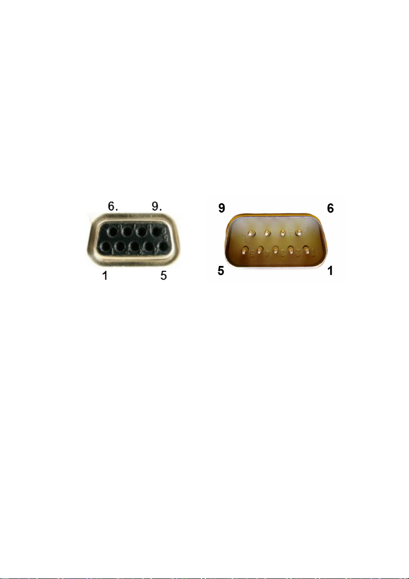
D-Sub DE9: Power, Data and Audio Connections ...................... 12
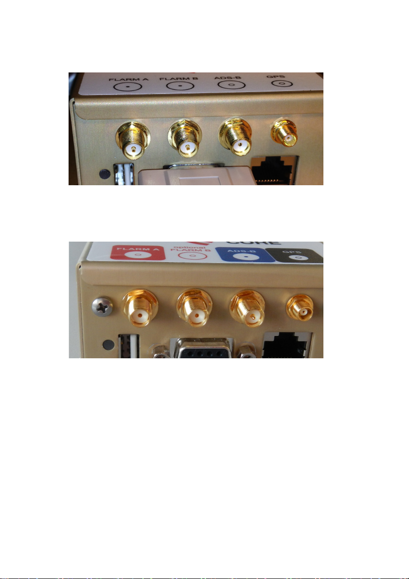
FLARM antennas (SMA connector, RED marking).................... 16
PCAS/ADS-B antenna (SMA connector, BLUE marking)........ 16
GPS antenna (MCX connector) ........................................................... 16
USB................................................................................................................ 17
Status LED indications .......................................................................... 18
Configuration............................................................................................ 20
Operation with Swiss Bat/Aboba v3+/v4 displays.................... 20
Essential Settings Prior to First Flight............................................ 21
Selection of Aircraft Type...................................................................... 21
Transponder................................................................................................ 21
ICAO Address............................................................................................... 21
Data Output................................................................................................. 22
Range Settings............................................................................................ 22

PowerFLARM Core Manual v.150 International
3
IGC settings .................................................................................................. 22
IGC task declaration ................................................................................ 22
Flight recorder .............................................................. 22
Feature licenses ............................................................ 23
Device identification.............................................................................. 24
Device update............................................................... 25
Software, license and/or obstacle database update................. 25
Mandatory firmware update.............................................................. 25
Butterfly (BF) software/FlarmNET update.................................. 25
Technical specifications................................................. 27
Notes............................................................................ 28
Product Warranty................................................................................... 28
Replacing ‘Classic’ FLARM by PowerFLARM ............................... 28
Limitations................................................................................................. 28
FLARM® Radio Communication....................................................... 29
Legal Liability ........................................................................................... 30
Conformity Declaration........................................................................ 31
Maximum Antenna Gain....................................................................... 32
Industry Canada Notice and Marking............................................. 33
Appendix A: Mechanical Drawings ............................... 34
Core............................................................................................................... 34
FLARM and PCAS/ADS-B antenna ................................................... 35
Appendix B: Antennas................................................... 35

PowerFLARM Core Manual v.150 International
4
Parts List
Your PowerFLARM Core contains the following parts:
•1 Core (golden metallic box)
•1 FLARM radio antenna with 1m/3ft cable and SMA connector
marked RED
•1 GPS antenna with 2m/6ft cable
•1 PCAS/ADS-B antenna with 1m/3ft cable and SMA connector
marked BLUE
•1 power / data cable D-Sub DE9 with 1m/3ft cable and an
open-cut end
•1 USB extension cable (deliveries after January, 2014)
The supplied antennas are suitable for in-cabin installation only.
See the Installation section for considerations when using external
antennas.
PowerFLARM Core does not have an integrated display, but con-
nects to a wide range of display interfaces, PDA’s, on-board flight
computers, moving map applications and MFD.
The typical installation connects to a Remote PowerFLARM Display.
Suitable cables providing power and data are delivered with the
display.
Cable extensions, a choice of antennas and other accessories are
available from your PowerFLARM dealer.
Working Principle
Based on GPS and the pressure sensor, PowerFLARM predicts your
short-term future flight path and continuously transmits this to
nearby aircraft by a digital radio message. FLARM-compatible sys-
tems in nearby aircraft receive your radio message and send you a
similar message with their data. With such you not only know the
whereabouts of aircraft around you, your Core is also able to calcu-
late conflicting flight patterns and alert you of such traffic on a suit-
ed display (FLARM functionality).
PowerFLARM also receives data from aircraft with transponders
(Mode C and S) or ADS-B OUT (1090ES), and uses these messages
for traffic information and alerts (PCAS functionality).

PowerFLARM Core Manual v.150 International
5
If available, PowerFLARM uses the barometric altitude from a Mode
S transponder installed on the same aircraft. If not, PowerFLARM
uses barometric altitude derived from the built-in pressure sensor.
Barometric altitude is used for determining the relative altitude to
PCAS targets.
The effective range depends very much upon the position in which
antennas are fitted and facilitates a warning, visual identification,
and appropriate action by the pilots in both aircraft.
FLARM-warnings are issued in accordance with the time remaining
to a possible collision, not the geometric distance between the air-
craft. The first warning is typically issued between 19 and 25 sec-
onds in advance to the calculated possible collision with aircraft or
obstacle (time to impact); the second is issued 14 to 18 seconds in
advance, and the third 6 to 8 seconds in advance. Warnings are
sustained as long as the threat remains as calculated. Depending
upon the prediction, the threat may be downgraded or deleted.
Warnings are selective, i.e. they are only issued if the calculation
detects a high probability of a collision in the immediate future.
PowerFLARM also warns about obstacles on the ground (cables,
masts, etc.) if the respective database is installed. Databases are
available for purchase on https://flarm.com/shop/.
Warnings are disabled if the own aircraft is considered taxiing or
stationary on the ground.
ADS-B alerts
ADS-B OUT broadcasts have originally been designed for ground-
based surveillance and collision avoidance by Air Traffic Control.
The use of ADS-B for airborne collision alerts is often limited by
factors such as:
•Absence of horizontal and/or vertical speed data
•Absence of GPS altitude data
•Erroneous transmission of position and/or velocity data
•Time lag in position data
Practical experience shows that airborne alerts based on ADS-B can
be useful to warn about powered traffic in cruise or relatively flat
turns such as standard procedure turns.

PowerFLARM Core Manual v.150 International
6
However, ADS-B does not provide sufficiently precise data to warn
about glider traffic with its frequent altitude changes and steep
turns.
To ensure best alert quality, PowerFLARM therefore does not use
ADS-B data to compute alerts for glider targets. Instead, it will ex-
clusively rely on the target's much more precise FLARM data.
This requires that all gliders which are equipped with FLARM and
ADS-B transponders to correctly configure their ADS-B out emitter
category to glider. Please refer to your transponder's manual in
order to make that configuration. To ensure reliable alerts, it is
important that gliders equipped with ADS-B transponders also car-
ry a compatible FLARM or PowerFLARM device and that both de-
vices are configured to the same ICAO address.
Please contact your local dealer if you're experiencing difficulties
with the above recommendations your flying area.
Installation
General Advice on Installation
Installation and operation is on a non-interference and non-hazard
basis, and may not endanger the safe operation of certified equip-
ment that is either necessary or required by regulation for safe
flight. Installation must comply with official requirements. In EASA
countries, an MCA (Minor Change Approval) or Standard Change
installation with appurtenant documents is requires. This can be
acquired from:
https://flarm.com/shop/easa-minor-change-approval-mca/.
Core must not obstruct the pilot in his operation of the aircraft (in-
cluding emergencies); in particular, at all times it must not obstruct
his view of the airspace, even in the event of serious vibration or
acceleration. Core is not suitable for use in conjunction with night
vision equipment, for night flying, or in pressurized cabins.
Only one single FLARM-compatible system may be installed per
aircraft.
Core should be located at least 1ft away from the magnetic compass.

PowerFLARM Core Manual v.150 International
7
After installation, an inspection must be made to ensure that the
Core does not interfere with any mechanical, electrical, electronic
(radio) or magnetic (e.g. compass) system, and this fact must be
recorded in the aircraft documents. In addition, the aircraft docu-
ments must bear a record of the PowerFLARM Core serial number
and Software Version Number. The Means of Compliance must be
recorded in the aircraft documentation and an AFM Supplement is
to be carried on board the aircraft. An EASA approved AFM Sup-
plement is available as part of the MCA (Minor Change Approval)
linked above.
Please see also the Quick Checklist for FLARM installation on
http://flarm.com/support/manuals-documents/.
Cabling
General advice
•Before connecting your cables for the first time, check all
connectors with a continuity tester. Pay special attention to
the Power Supply pins.
•For updates and configuration, the USB connector must be
accessible, where required with an installed extension ca-
ble.
•Cables must not be cracked or installed under tension. Ade-
quate space must be left for the cable connectors.
Power supply
•Supply voltage: 8 to 35VDC.
•Typical current drain 165 mA @ 12V, less for higher volt-
ages, more if external components are supplied by Power-
FLARM.
•Connect power either through the D-Sub (pin 7) or the RJ45
connector (pin 1 and 2); do not provide power to both!
Circuit breaker
•Connect PowerFLARM Core via a dedicated pilot-operated
1-3 A CB or combined CB/Switch.

PowerFLARM Core Manual v.150 International
8
•The PowerFLARM CB must be separate from other CBs of
essential avionics.
•In flight the pilot must be able to isolate PowerFLARM Core
from the aircraft's electrical power system without inter-
rupting the power supply to other essential avionics.
Display
•Use high quality shielded cable for the RX and TX connec-
tions.
•Up to 5m cable length are acceptable.
•In case the display requires 3VDC operating voltage, the re-
spective connection on the RJ45 or D-Sub connector may be
used. Otherwise, the display should be supplied directly
from the aircraft’s bus and protected by its own CB as per
the display’s installation manual.
External antennas
The antennas provided with PowerFLARM Core are suitable for in-
cabin use only. External antennas for FLARM and ADS-B are howev-
er recommended for most aircraft. If external antennas are in-
stalled, please follow the considerations below.
•Ensure high quality in custom-made cable/connector as-
semblies.
•Minimize cable lengths to ensure maximum signal strength.
•Antennas should be spaced at least 30cm apart, including
other antennas like COM/NAV, XPDR etc.
•See also the ‘Connections’ section for antenna and place-
ment considerations.
FLARM A/B
•Use low-loss 50Ω coaxial cable such as Aircell 7, RF-240,
LMR-195, RG-58 or RG-174.
•Total attenuation of the cable at 900MHz should not exceed
3dB. This translates into a maximum cable length of ca.
15m for Aircell 7 or 3m for RG-174.

PowerFLARM Core Manual v.150 International
9
•If higher cable lengths are required, even lower loss cables
such as LMR-400 should be considered.
•Suitable antennas: FLARM AV-75 (part. No. ANTCEFLA and
ANTCEFLAB); available from your FLARM dealer.
•The primary antenna (FLARM A) should have good view in-
to the direction of flight. FLARM B (if used) should be
placed to complement the field of view of FLARM A.
ADS-B
•Suitable antennas: RAMI AV-74 Transponder/DME antenna
or similar; available from your FLARM dealer.
GPS
•Use low-loss 50Ω coaxial cable. Attenuation values at
1.57GHz are relevant.
•The required MCX connector can be directly crimped to RG-
316 and Enviroflex (ca. 1.4dB/m). If thicker cables are re-
quired, an adapter must be used.
•Use a low-profile aviation GPS antenna with builtin pream-
plifier, e.g. Sensor Systems S67-1575-39 or S67-1575-49;
available from your FLARM dealer.
•Preamplifier gain minus cable attenuation must exceed
17dB.
•The antenna must accept PowerFLARM’s 4.75V supply and
must not draw more than 200mA. DC resistance of the ca-
ble must be taken into account.
•The antenna should be mounted horizontally with a good
sky view.
•Operation with an existing GPS antenna and an RF splitter
may be possible provided the antenna has a high gain pre-
amplifier and cable losses are not too high. A splitter with a
DC block on one path must be used. Please contact your
dealer or FLARM if you plan using a splitter.

PowerFLARM Core Manual v.150 International
10
Housing
The metallic housing is not waterproof and users should avoid the
ingress of solid particles and liquids. Should the unit get moist, it
must be completely dried prior to further use. If the unit becomes
wet, it may be permanently damaged and rendered unusable; no
warranty claim will be accepted for any unit damaged by moisture
or liquids. Should the unit be suddenly cooled this may result in the
formation of condensation.

PowerFLARM Core Manual v.150 International
11
Connections
Overview
Core has the following connectors:
•USB 2.0: Flight log readout, device update and configuration
•FLARM antennas A and B: When using a single antenna, connect
to FLARM A. Antenna connector has a RED marking. Use of
FLARM B requires a feature license.
•ADS-B/PCAS: For receiving transponder signals. Antenna con-
nector has a BLUE marking.
•GPS antenna: Must be connected for proper operation in flight.
•Data Ports #1 (RJ45) and #2 (D-Sub DE9): For connecting up to
two independent displays/PDAs/flight computer. Also used for
power supply of Core. RX/TX on ports #1 and #2 can be config-
ured and used independently.
RJ45: Power and Data Connections
The 8-pin RJ45-socket is in accordance with IGC GNSS FR specifica-
tions, except for pin 3. Pin numbering follows IGC’s convention
(http://www.fai.org/gnss-recording-devices/igc-approved-flight-
recorders ):
1: +12 to +28VDC power supply
2: +12 to +28VDC power supply
3: Core supplies +3VDC for display
4: GND
5: TX, Core sends (RS232)
6: RX, Core receives (RS232)
7: GND
8: GND
Pin 1 Pin 8

PowerFLARM Core Manual v.150 International
12
Pin 5 transmits NMEA-0183 Version 2.0 data at a configured data
rate (default is 19.2kBaud). Further FLARM-specific data is availa-
ble for periphery devices (e.g. remote display).
Do not connect more than one external application to the port.
Maximum current on pin 3: 200mA @ 3VDC.
D-Sub DE9: Power, Data and Audio Connections
The 9 pin DE9 connector is shown below. On the left side the female
socket on the PowerFLARM is shown. On the right side the male
plug (on the cable) is shown.
1: Audio OUT (referenced to GND; H/W versions >= 1.1 only)
2: TX, Core sends (RS232)
3: RX, Core receives (RS232)
4: Do not connect
5: GND
6: Do not connect
7: +12 to +28VDC power supply
8: Core supplies +5VDC for PDA
9: Core supplies +3VDC for display
Pin 2 transmits NMEA-0183 Version 2.0 data at a configured data
rate (default is 19.2kBaud). Further FLARM-specific data is availa-
ble for periphery devices (e.g. remote displays).
Do not connect more than one external application to the RS232
port.
Maximum current on pin 9: 200mA @ 3VDC; independent of pin 3
of the RJ45 connector.

PowerFLARM Core Manual v.150 International
13
Maximum current on pin 8: 700mA @ 5VDC; shared with the USB
port.
Avoid using the 5VDC supply from the USB port and the D-Sub port
at the same time.
WARNING!
The below color assignments are only valid for specific D-Sub
cables which have been shipped with devices from 2016.
D-Sub cables shipped with PowerFLARM Core devices from 2016
are color coded according to the following table. These D-Sub cables
are marked with “Art.-Nr 1420531”. DO NOT use the color coding
if the cable is not marked accordingly.
Grey
Pin 1: Audio OUT
Yellow
Pin 2: TX, Core sends (RS232)
Green
Pin 3: RX, Core receives (RS232)
Brown
Pin 4: Do not connect
White
Pin 5: GND
Red
Pin 7: +12 to +28VDC power supply
Pink
Pin 8: Core supplies +5VDC for PDA
Blue
Pin 9: Core supplies +3VDC for display
Note: There is no wire for Pin 6!
Pin 7 of the D-Sub connector and Pins 1 and 2 of the RJ45 con-
nector are internally connected. So are the GND pins 5 (D-Sub)
and 4, 7, 8 (RJ45).

PowerFLARM Core Manual v.150 International
14
Audio OUT
Audio OUT (pin 1) is available for hardware version 1.1 and later
(FLAPFC11...), provided the corresponding feature license is in-
stalled. PowerFLARM emits 1kHz beeps on Audio OUT whenever
dangerous traffic is detected. A test beep is emitted after power up.
Dedicated PowerFLARM displays have their own sound generator
(buzzer). Audio OUT is only necessary when the buzzer of the con-
nected PowerFLARM display(s) is not loud enough to be heard in a
high-noise environment.
Electrical characteristics:
•AC signal, 1.7V peak-to-peak @ 1 kOhm
•Referenced to GND (pin 5), no DC bias
•Output impedance: 47 Ohm
•Output current (max.): 35mA
Connect Audio OUT to audio panels or other amplifiers with input
impedance between 200 Ohm and 10 kOhm. The audio panel or
amplifier should allow volume adjustment.
Do not connect a passive headset or speaker directly to Audio
OUT. If you are unsure about how to connect Audio OUT, con-
tact your dealer.

PowerFLARM Core Manual v.150 International
15
FLARM and PCAS/ADS-B antenna connectors (SMA)
US/Australia devices (part No. FLAPFCnnA and FLAPFDnnA):FLARM
A and B are reverse polarity female SMA connectors with a pin as
center conductor. ADS-B is a standard female SMA connector with a
female center sleeve.
European devices (part No. FLAPFCnnE and FLAPFDnnE):FLARM A
and B ports are standard female SMA connectors with a female
centre sleeve. ADS-B is a reverse polarity female SM connector with
a pin as a centre conductor.
Never swap the FLARM and PCAS/ADS-B antennas. Doing so
may cause permanent mechanical damage to the device and
will void warranty.
The difference between US/Australia and European devices is due
to regulatory requirements.
Both FLARM and the ADS-B antennas must be mounted vertically
(i.e., one tip facing up, the other one down).

PowerFLARM Core Manual v.150 International
16
FLARM antennas (SMA connector, RED marking)
Core has two separate FLARM radio transceivers FLARM A and
FLARM B. FLARM A is used to receive and transmit and must
always be connected to an antenna. FLARM B is only used to re-
ceive; an optional antenna may be used for better reception per-
formance.
Usage of FLARM B requires purchase of the respective feature li-
cense.
Ensure the antennas are properly and fully screwed into Core. Nev-
er swap the FLARM and the PCAS/ADS-B antennas. Use only
little force when inserting and tightening (1 Nm max). Ensure the
antennas are not in contact with any other object through which
there might be a regular electrostatic discharge, e.g. the canopy. In
case you use two FLARM antennas, ensure they are separated by at
least 5ft.
Ideal locations for the FLARM antenna are:
•On the coaming of the instrument panel, in front of the compass
(4 inch, 10cm minimal distance to compass)
•In the tail fin of the aircraft, if not metallic or carbon. Use only
extension cables available from FLARM dealers.
•Behind the pilot’s head in the glider fuselage (not in gliders
with carbon fuselage)
The FLARM antenna must be vertically (i.e., one tip facing up, the
other one down.
PCAS/ADS-B antenna (SMA connector, BLUE marking)
Core has one PCAS/ADS-B receiver operating on 1090MHz. Ensure
you properly and fully screw the antenna stub into Core. Never
swap the FLARM and the PCAS/ADS-B antennas. Use only little
force when inserting and tightening (1 Nm max).
This antenna should be placed at least 1ft away from the FLARM
antenna(s). The FLARM antennas have priority over this antenna
for best placement.
GPS antenna (MCX connector)
PowerFLARM Core contains a 50 channel GPS receiver, connecting
to an external antenna. Ensure you properly and fully plug the GPS

PowerFLARM Core Manual v.150 International
17
antenna cable connector into Core. PowerFLARM will not work
without good GPS reception.
The GPS antenna should be located in a horizontal position such
that it has an unhindered sky-view, including when the aircraft is in
a turn. There should be no electrically conducting surfaces (e.g.
metal, carbon fibre) over or immediately alongside the antenna.
Ideally, the antenna will sit atop the instrument panel coaming.
Conducting surfaces under the antenna may have a positive effect
upon antenna function.
If more than one GPS antenna is present in the aircraft, it is recom-
mended that they are at least 1ft apart; the same holds for separa-
tion from all other Core antennas.
USB
Core has a built-in USB A 2.0 connector for a memory stick. The
stick is used for device updates and readout of device information
and flight records. See the section ‘Device update’, ‘Flight recorder’
and ‘Feature licences’ for details. Maximum size is limited by FAT
system (32GB).
The USB stick must not be connected during flight except for
special purposes as advised by FLARM Technology or its agents.
USB stick transactions take place:
•Whenever PowerFLARM is switched ON with a USB stick con-
nected.
•When triggered by a display or flight computer (currently im-
plemented: Readout of flight records).
Transactions after switching PowerFLARM ON are executed in the
following sequence:
•Apply device configuration (FLARMCFG.TXT)
•Write device information (FLARMDEV.CSV)
•Updates: Firmware, obstacle database, licences. (PowerFLARM
restarts if any update is done (Status LED OFF for three sec-
onds); this is to allow expedited updates of multiple devices.)

PowerFLARM Core Manual v.150 International
18
•Butterfly display firmware update
•Flight record readout
USB sticks should:
•be formatted with FAT (FAT16 or FAT32) file system (NTFS or
exFAT will not work)
•have capacity <= 32GB
•Be of USB 2.0 type (not USB 3.0; USB 3.0 connectors are typical-
ly blue on the inside).
Suggestions for USB stick usage:
•Use a dedicated USB stick for your PowerFLARM device(s) (Ex-
ception: Updates of multiple devices to the same software
and/or obstacle DB).
•Leave flight logs (IGC files) on your USB stick during the flying
season. This will reduce the time needed for readout, because
files already on the stick are skipped.
•Sort IGC files by date on your PC. The last file in the list then
corresponds to the most recent flight.
•If multiple firmware update files are on the USB stick, Power-
FLARM will chose the most recent one.
•Do not keep multiple obstacle database updates on your USB
stick.
•PowerFLARM will skip firmware, license and obstacle database
updates which are already installed.
Status LED indications
The Status LED can show three different colors: GREEN, ORANGE
and RED.
Please note that ORANGE may appear similar to RED. The color
during the first few seconds after startup is ORANGE.
The meaning of the Status LED indications is as follows:
•GREEN: Core operates normally
•ORANGE during start-up sequence: May take up to 20s

PowerFLARM Core Manual v.150 International
19
•Permanent RED: Error condition, no operation possible (e.g. no
GPS reception, low voltage)
•Permanent ORANGE: Warning condition, operation possible
(e.g., obstacle database out of date)
•RED/GREEN flashing: on-going data upload/download with
USB memory stick
•OFF: no power
Indications while reading FLARMCFG.TXT files:
•One long GREEN flash: USB stick detected
•One short GREEN flash for each command executed suc-
cessfully
•One short RED flash for each command causing an error
(verify FLARMCFG.TXT in that case)

PowerFLARM Core Manual v.150 International
20
Configuration
Prior to first use, PowerFLARM Core must be configured correctly.
Failure to configure or a false configuration may lead to failure
to alert, operate or cause nuisance alarms!
To configure your Core:
•Use the online Configurator tool to generate a file FLARM-
CFG.TXT: http://flarm.com/support/tools-software/
•Copy this file to the top directory of your USB stick.
To update many devices using one USB stick, name each
configuration file as follows: CF<Product Code><5 last dig-
its of Serial Number>.txt, where Product Code is the 6th let-
ter from Part Number ( C, D, P, or Q ), which you can find on
device sticker. Example: Part Number FLAPFD11E, Serial
Number 002217, Configuration file name CFD02217.txt
•Connect the stick to the Core and power on the system.
•Wait until the system has completed the startup sequence.
The Status LED will issue a long GREEN flash to acknowledge the
presence of the FLARMCFG.TXT file and a short GREEN flash for
each configuration line executed. RED flashes indicate an error,
please verify your FLARMCFG.TXT file in that case.
Please use FAT formatted USB 2.0 sticks; see the USB section for
details.
The configuration is stored permanently in Core internal memory.
During normal operation, the USB stick should be removed from the
Core.
All configurations can also be made via the RS232 interfaces of the
Core. Please refer to your display or flight computer’s documenta-
tion for details.
Operation with Swiss Bat/Aboba v3+/v4 displays
•Select ‘Traffic Data Only’ for the ‘Data Sentences’ option.
•Select ‘Default’ for the ‘Data sentences protocol’ option.
Other manuals for PowerFLARM Portable
3
Table of contents
Other FLARM Industrial Equipment manuals
Popular Industrial Equipment manuals by other brands

FRIEDHELM LOH
FRIEDHELM LOH Rittal SK 3363 Series Assembly and operating instructions

Borum
Borum BOD1906 owner's manual

C.E. Nierhoff & Co
C.E. Nierhoff & Co C815 troubleshooting guide

Woodward
Woodward easYgen-3000XT Series instructions

SCHUNK
SCHUNK DPG-plus Series Assembly and operating manual

GAGEMAKER
GAGEMAKER PN-3000 Series Operation manual