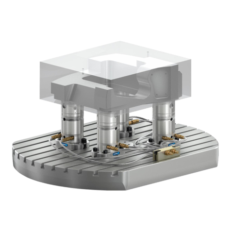
coval CVGL User manual

Retrouvez tous les documents en différentes langues sur le site COVAL : https://doc.coval.com/CVGL
All documents are available in multiple languages on the COVAL website: https://doc.coval.com/CVGL
Finden Sie alle Dokumente in verschiedenen Sprachen auf der COVAL-Homepage: https://doc.coval.com/CVGL
Tutti i documenti nelle differenti lingue sono presenti sul sito COVAL: https://doc.coval.com/CVGL
Podrá encontrar todos los documentos en diferentes idiomas en la página web de COVAL: https://doc.coval.com/CVGL
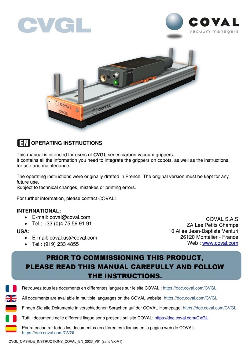
CVGL
Compact and Light Vacuum Grippers
OPERATING INSTRUCTIONS
This manual is intended for users of CVGL series vacuum
grippers.
It contains all the information you need to integrate the grippers,
as well as the instructions for use and maintenance.
The operating instructions were originally drafted in French
(original version).
They must be kept for any future use.
Subject to technical changes, mistakes or printing errors.
For any additional information, please contact COVAL:
International:
E-mail: coval@coval.com
Tel: +33 (0)4 75 59 91 91
COVAL S.A.S. (Head Office)
ZA Les Petits Champs
10 allée Jean-Baptiste Venturi
26120 Montélier France
Web : www.coval.com
USA:
E-mail: contact.us@coval.com
Tel: (919) 233 4855
COVAL VACUUM TECHNOLOGY INC.
901 Jones Franklin Road
Suite 100
Raleigh, NC 27606
Web: www.coval-inc.com
CVGL_CMSHDE_INSTRUCTIONS_COVAL_EN_2023_V1.03
PRIOR TO COMMISSIONING THIS PRODUCT,
PLEASE CAREFULLY READ THIS MANUAL AND FOLLOW THE INSTRUCTIONS.
EN

-2-
www.coval.com
EN
CVGL series
Vacuum Grippers OPERATING INSTRUCTIONS
SUMMARY
1. IMPORTANT INFORMATION ......................................................................... 3
2. SAFETY INSTRUCTIONS............................................................................. 3
3. INSTRUCTIONS FOR USE............................................................................ 4
3.1. Basic Installation ..........................................................................................4
3.2. Commissioning and Decommissioning.....................................................4
3.3. Operating the Vacuum Gripper..................................................................5
3.4. Transportation and Storage.......................................................................5
3.5. Maintenance..................................................................................................5
3.6. Disposal.........................................................................................................5
4. NAMEPLATE ............................................................................................... 5
5. IDENTIFYING YOUR MODEL........................................................................ 6
6. TECHNOLOGIES USED................................................................................ 8
6.1. Gripping Interface.........................................................................................8
6.2. Flow Control Technologies..........................................................................9
7. OVERVIEW, DIMENSIONS, AND MOUNTING ................................................ 9
7.1. Overview .........................................................................................................9
7.2. Dimensions and Mounting Options .......................................................... 10
7.3. Gripping Interface Dimensions .................................................................12
8. CHARACTERISTICS....................................................................................13
9. INSTALLING THE VACUUM GRIPPER .........................................................14
9.1. Pneumatic Supply for Vacuum Grippers Equipped with One or More
CMS HDE Vacuum Generators...........................................................................14
9.2. Pneumatic Connection...............................................................................14
9.2.1. CVGL Versions D1 and D2............................................................................................. 15
9.2.2. CVGL Version D3........................................................................................................... 15
9.2.3. CVGL Version G0........................................................................................................... 15
9.3. Connecting a Vacuum Switch ...................................................................16
9.4. Electrical Connections: CVGL with Vacuum Generator Control
(versions S and V)...............................................................................................16
9.5. CVGL with Vacuum Level Display (Versions VA and VF).........................17
10. INSTALLING AND OPERATING REMOTE HMI (CVGL VERSION VI)............ 17
10.1. Dimensions..................................................................................................17
10.2. Installing the Remote HMI, part no. HMIHD1M84P..................................18
10.3. Conguring a Remote HMI........................................................................18
10.4. Front Panel Dialog .....................................................................................19
11. HMI DETAILS AND FEATURES ...................................................................19
11.1. Powering On .................................................................................................19
11.2. Details of the Main Screen ........................................................................19
11.3. Keypad Functions......................................................................................20
12. SUMMARY OF FUNCTIONS ......................................................................20
12.1. Accessing Live Diagnostic Data ..............................................................20
12.2. Menu Tree....................................................................................................21
13. LOCKING/UNLOCKING THE KEYPAD....................................................... 22
14. PROCESS SETTINGS ............................................................................... 22
14.1. Setting Threshold 1....................................................................................22
14.2. Auto Blow-off.............................................................................................23
15. USER SETTINGS...................................................................................... 23
15.1. Language ....................................................................................................23
15.2. Screen.........................................................................................................23
15.3. Units............................................................................................................23
16. DEVICE SETTINGS...................................................................................24
16.1. Input/Output Switching Mode: PNP or NPN ...........................................24
16.2. NO / NC.......................................................................................................24
17. DIAGNOSTICS ..........................................................................................24
17.1. Device Info..................................................................................................24
17.2. Cycle Counters...........................................................................................24
17.3. Manual Mode...............................................................................................25
17.4. Calibration..................................................................................................25
17.5. Reset Settings............................................................................................26
18. EVENTS AND ALARMS ............................................................................ 26
19. IO-LINK PARAMETER SETTINGS............................................................. 27
19.1. IO-Link Communication............................................................................27
19.2. Cyclical Data (PDI/PDO)............................................................................27
19.3. Acyclical Data............................................................................................28
20. NFC......................................................................................................... 29
20.1. Technical Data ..........................................................................................29
20.2. Using NFC..................................................................................................29
20.3. Functionality.............................................................................................30
20.4. Downloading the COVAL VACUUM MANAGER NFC App .........................30
21. OPERATING THE VACUUM GRIPPER........................................................ 30
21.1. Version with Foam Gripping Interface....................................................30
21.1.1. Version with foam and ow control technology using valves............................. 31
21.1.2. Version with foam and ow control technology using ow control nozzle.... 32
21.2. Version with Suction Cup Gripping Interface .......................................33
21.3. Version with COVAL-ex Gripping Interface .........................................34
22. MAINTENANCE ....................................................................................... 35
22.1. Frequency ..................................................................................................35
22.2. Assembling/Disassembling Gripping Interfaces .................................36
22.3. Replacing the Gripping Foam.................................................................36
22.4. Replacing Suction Cups ..........................................................................37
22.5. Disassembling the CMS HDE Series Vacuum Generator.....................37
22.6. Maintenance Procedures for a Vacuum Generator,
CMS HDE Series..................................................................................................38
22.6.1. Cleaning the lter screen on the compressed air supply................................. 38
22.6.2. Cleaning the vacuum lter and the vacuum check valve................................ 38
22.6.3.Cleaning the multi-stage venturi proles ............................................................40
22.6.4. Replacing the solenoid valves................................................................................. 41
22.6.5. Replacing the pressure connection end plate for CMSHDE90X__NVO............ 41
22.6.6. Replacing the valve block for CMSHDE90X__SVOC15P / VVOC15P
and CMSHDE90X__SVX_ / VVX_............................................................................................ 41
22.6.7. Replacing the exhaust silencer.............................................................................. 42
22.7. Performing Airtightness Test on Vacuum Gripper...............................42
23. SPARE PARTS......................................................................................... 43
23.1. Foam Gripping Interface..........................................................................43
23.1.1. Complete spare foam gripping interface.............................................................. 43
23.1.2. Spare foam bases ..................................................................................................... 44
23.2. Suction Cup Gripping Interfaces ...........................................................44
23.2.1. Complete replacement suction cup gripping interface.................................... 44
23.2.2. Spare suction cups .................................................................................................. 45
23.3. CMS HDE Series Multi-Stage Vacuum Generators
for CVGL___D1, D2, or D3...................................................................................46
23.4. Spare Parts for CMS HDE Series Vacuum Generators........................46
23.5. Vacuum Switch and Vacuum Gauge .....................................................50
23.6. Accessories...............................................................................................50
24. GLOSSARY.............................................................................................. 50
25. WARRANTY.............................................................................................50
26. RECYCLING.............................................................................................50
27. DECLARATION OF CONFORMITY..............................................................51

-3-
www.coval.com
1. IMPORTANT INFORMATION
This document contains important instructions and information regarding various stages in the life cycle of the product:
Transportation, storage, commissioning, and decommissioning.
Operation and service.
The operating instructions correspond to the product actually delivered.
This document is part of the product and the instructions below must be followed:
Read this document carefully and observe the instructions to ensure safe installation, optimal operation of the product, and to avoid
any malfunction.
Keep the document within reach of the product so operators can easily access it.
Failure to observe the instructions specied in this document may lead to injury or even death!
COVAL will not be held liable for any damage or breakdown resulting from failure to follow instructions.
For any additional information, please contact COVAL:
International: USA:
E-mail: coval@coval.com E-mail: contact.us@coval.com
Tel.: +33 (0)4 75 59 91 91 Tel: (919) 233 4855
2. SAFETY INSTRUCTIONS
Only qualied personnel should be authorized to use the components. These individuals must be trained in the following areas:
Installing pneumatic and electric equipment.
Applicable safety rules and requirements for using components and installing them in devices, machines, and production lines.
Appropriate handling of components and their respective products.
Proper use of the operating materials and supplies.
The latest applicable EC directives, legislations, decrees, and standards, as well as the current state of the technology for its intended
use.
Any special measures necessary to meet these requirements, as well as the current state of the technology.
Installation in a secure environment.
The vacuum gripper is solely intended for use in automated applications and in secure areas.
The improper use of components, use of operating materials and supplies other than those dened, improper voltages, and/or other
environmental conditions may lead to failure, damage, and/or injury.
This list must be considered as an overview and does not claim to be exhaustive. It can be further expanded by users according to their
particular needs.
NOTE:
This document provides detailed operating instructions for the standard models referenced in chapter 5. For custom models, the
information herein must be adapted to the specific features of the product. Custom versions are products that have been tailored to
meet the constraints of a specific application. The following are examples of such custom models:
Different product lengths
Multi-zone
Different suction cups
Different accessories
EN
CVGL series
Vacuum Grippers OPERATING INSTRUCTIONS

-4-
www.coval.com
HAZARD AREAS
Area where there is a risk of crushing Area where there is a risk of air ejection
Notes for the manufacturer of the nal machinery and for the end user
Standing or walking in the operating area of the vacuum gripper is strictly prohibited. In the event of a power or pneumatic supply
failure, the load handled by the gripper will be released.
Never look inside and/or introduce hands into cavities, holes, or openings (e.g. air exhausts, openings/holes under the suction cups,
etc.).
The vacuum gripper described in this manual is designed for implementation in industrial systems. In other words, It must not be used
under any conditions other than those specied.
Once the vacuum gripper is installed, the manufacturer of the nal machinery is responsible for the nal assessment of safety systems
applied prior to putting the facility into operation. It is the responsibility of the manufacturer of the nal machinery to specify the
PPE required for operators standing in the vicinity as well as for those who have access to the operating area. Furthermore, the said
manufacturer must certify nal commissioning in accordance with applicable local rules and regulations.
3. INSTRUCTIONS FOR USE
3.1. Basic Installation
In order to ensure awless installation and operation, the following rules must also be observed:
Vacuum grippers must be carefully removed from their packaging.
Vacuum grippers must be protected against any and all damage.
During installation and maintenance work, the vacuum generator must be de-energized (air and power) and secured against any
unauthorized activation.
Any attempt to alter the vacuum gripper is strictly prohibited.
The area surrounding the vacuum gripper and the location where it is used must be kept clean (no outdoor use).
Only the ttings/connectors provided may be used.
During installation, only exible tubes and tubes that are suitable for the specic operating material may be used (Improper tubing and/
or electrical lines are a major safety hazard- including risk of death!).
Conductive and live cable lines must be insulated, of an adequate size, and properly installed.
Pneumatic and electric lines must be connected to the component in a stable and safe manner.
Ensure that any physical contact with electric parts is prevented (protect electrical contacts).
Only available fastening means described in this document maybe used and tightening torques must be used accordingly.
The possibility of power or pneumatic supply interruption must be taken into consideration to ensure people and systems are protected
at all times.
Emergency stops should be accounted for when designing the system.
3.2. Commissioning and Decommissioning
Commissioning:
Ensure the exible tubes for compressed air and power supply are connected correctly using the appropriate connectors.
Decommissioning (prior to any disassembly or maintenance work):
Ensure the gripper is not holding any objects (load may drop).
EN
CVGL series
Vacuum Grippers OPERATING INSTRUCTIONS

-5-
www.coval.com
XXXXXXXXXXXXXXXX…
CVGL424DVSA33JKXHXD1S1KVA
2,520 KG
www.coval.com
Intended use
The vacuum gripper is solely intended for use in automated applications and in secure areas.
Use cases depend on the gripping interfaces used see chapter 6.
Unintended use
The vacuum gripper may not be used for the following:
Manual applications.
Uses other than those established by the manufacturer or specied in this manual.
In direct contact with hazardous materials (molten masses, radioactive products), water, steam, or in environments where
dripping or splashing water, oil, etc. may occur.
In explosive, acidic, alkaline, or saline atmospheres.
In environments subject to strong vibrations and/or shocks.
3.3. Operating the Vacuum Gripper
3.4. Transportation and Storage
When handling the vacuum gripper, only use equipment that is suitable for its dimensions and weight.
For proper storage of the system and its spare parts, we recommend the following:
Do not store in outdoor areas or areas exposed to bad weather, excessive moisture, or direct sunlight
In a reasonably clean environment, place the system in such a way that it rests on a stable support base, and ensure that the device
cannot tip over.
Store the gripper in a manner where the interface is uncompressed.
3.5. Maintenance
Maintenance must be performed in accordance with the instructions in this manual. Prior to performing any maintenance work, follow the
instrutions provided in section 3.2.
3.6. Disposal
When disposing of the system or any of its constituent parts that are no longer functional, follow the procedure below:
Waste electrical and electronic equipment (WEEE) must not be disposed of in urban waste collection bins but given to the
appropriate recycling organization (see section 26 on RECYCLING).
Failure to observe the above safety instructions may lead to failure, damage, and injury—even risk of death.
The components of the device that are no longer in working order must be recycled in an environmentally-
friendly manner!
Sample nameplate
4. NAMEPLATE
The nameplate is axed to the vacuum gripper in such a way that it is legible at all times.
It includes the following information:
Part number
Serial number
Weight
CE marking
UKCA marking.
Always provide the part and serial numbers of the product when you contact COVAL.
EN
CVGL series
Vacuum Grippers OPERATING INSTRUCTIONS

-6-
www.coval.com
CVGL 424 D VSA33JK X H X D1 S 1 KVA
424
624
824
X H
Q
D
VSP14BF
VSA25JI
VSA33JK
MVS30EK
X
C
X
F
H
E
V
F2S
F2B
OVERALL LENGTH
424 mm
624 mm
824 mm
HOLE/CUP
PATTERN LAYOUT
Staggered
Straight*
* Only available for "maxi" type gripping interface
with minimum suction cup Ø 26mm.
"COVAL-flex" gripping interfaces are designed to respond to specific
applications. Our vacuum team will recommend and define any applications of
yours which can benefit from its special features.
SPECIAL VERSIONS
There can be instances where the standard CVGL versions will not match your application requirements.
COVAL can provide you personalized solutions based on your specifications, by integrating specific function and suggesting custom
lengths and suction cup types.
ASSEMBLY
TYPE
Screw mounting
Quick-mounting
spring clips
FILTER
Without
TECHNOLOGY
Flow control
nozzles
SUCTION CUPS GRIPPING INTERFACES
"mini" type interface:
2.5 bellows suction cups Ø 14 mm in
silicone 30 Shore with flow control nozzles
"medium" type interface:
1.5 bellows suction cups Ø 25 mm in
natural rubber with flow control nozzles.
"maxi" type interface:
1.5 bellows suction cups Ø 33 mm in
natural rubber with flow control nozzles.
"maxi" type interface:
2.5 bellows suction cups Ø 30 mm in
white silicone 35 Shore with flow control nozzles.
FILTER
Without
With
filter
TECHNOLOGY
Flow control
nozzles
Airtight valves
Check valves
FOAM GRIPPING INTERFACES
Foam "mini" type interface:
EPDM (thickness 20 mm)
Foam "maxi" type interface:
EPDM (thickness 20 mm)
GRIPPING INTERFACES
5. IDENTIFYING YOUR MODEL
EN
CVGL series
Vacuum Grippers OPERATING INSTRUCTIONS

-7-
www.coval.com
D1 S 1 KVA
G0
D1
D2
D3
VO
VA
VF
VI
X
K
N
N
S*
V*
0
0
1
2
* Only for D1 and D2.
VERSION WITHOUT
VACUUM GENERATOR
Without
vacuum generator
VERSIONS WITH
VACUUM GENERATOR*
1 x CMSHDE_50
multi-stage vacuum pump
Flow rate: 700 Nl/min
1 x CMSHDE_100
multi-stage vacuum pump
Flow rate: 1100 Nl/min
2 x CMSHDE_100
multi-stage vacuum pump
Flow rate: 2200 Nl/min
VACUUM LEVEL DISPLAY
Without
Vacuum switch with electronic display
Vacuum gauge
(for versions with control,
option available for 624 mm in length and longer)
HMI on CMS HDE
(compatible with S2 and V2 versions only)
EXHAUST
Without
EXHAUST
Through-type
silencer
GENERATOR
CONTROL
Without
GENERATOR
CONTROL
Without
CMSHDE__S_
Vacuum pump with
NC vacuum control
and NC blow-off
control.
Choice of blow-off
settings (only on
CVGL__S2_models):
Controlled by
external signal
Automatic timer
from 50 to 9999 ms
(advantage: saves
one controller
output).
CMSHDE__V_
Vacuum pump with
NO vacuum control
and NC blow-off
control.
Blow-off controlled
by external signal
GENERATOR
CONFIGURATION
Without
GENERATOR
CONFIGURATION
Without
CMSHDE____VOC15P_
Multi-stage vacuum
pump without vacuum
switch and HMI
One M12 5-pin male
PNP
Digital inputs/
outputs mode (SIO)
CMSHDE____VXC15X_
Multi-stage vacuum
pump with integrated
vacuum switch and
pressure sensor,
without HMI
One M12 5-pin male
configurable as
PNP or NPN
One M8 4-pin male
for remote HMI
Electronic vacuum
switch
Digital Output DO1
"object gripped" 24
V DC / NO
Digital input/outputs
mode (SIO) /
Compatible with
HMI (for VI option)
EN
CVGL series
Vacuum Grippers OPERATING INSTRUCTIONS

-8-
www.coval.com
6. TECHNOLOGIES USED
6.1. Gripping Interface
With CVGL, COVAL gives you a choice of 3 complementary gripping interface technologies: vacuum grippers with foam, suction cup
grippers, and grippers with a COVAL-ex interface.
In order to optimize the performance of the CVGL series for different applications, the vacuum grippers are available in different gripping
patterns, hole diameters, and cup sizes.
A broad range which meets all application requirements.
"FOAM" Interface
Handling of rigid products.
Gripping textured or uneven surfaces.
Flow control nozzles, airtight valves, or
check valves.
2 standard hole diameters (Ø 12, 16mm).
2 standard hole patterns.
3 standard lengths (424, 624, and 824mm)
or custom length.
"SUCTION CUP" Interface
Handling of exible products.
Wide range of cup options.
Flow control nozzles in multiple
diameters.
4 types of standard suction cups (Ø 14,
Ø25, Ø 30 and Ø 33 mm).
3 standard cup patterns.
3 standard lengths (424, 624, and 824mm)
or custom length.
"COVAL-ex" Interface
Handling of aluminum cans, canned food,
glass containers, etc.
Flexible interface, extremely tear-
resistant.
Hole pattern dependent upon application
requirements, completely customizable.
"MINI" type
Reduced hole spacing, allowing small,
exible pieces to be gripped.
The multitude of gripping points
guarantees a strong grip, even with
random positioning of products.
"MEDIUM" type
An intermediate distribution of gripping
points between the "mini" and "maxi" type.
Ideal for handling dense loads with
reduced gripping surface.
"MAXI" type
Large gripping point surfaces, allowing
heavy loads to be gripped.
Ideal for gripping parts with rigid gripping
surfaces.
Standard Hole/Cup Patterns
In order to optimize the performance of the CVGL series for different applications, the vacuum grippers are available in different gripping
patterns, hole diameters, and cup sizes.
Part number Total length of the vacuum gripper (mm) Force at 80% vacuum* (N) / (lbf) Force at 45% vacuum* (N) / (lbf)
CVGL 424_ _ _ _ 424 1035 / 232.6 600 / 134.9
CVGL 624_ _ _ _ 624 1550 / 348.4 900 / 202.3
CVGL 824_ _ _ _ 824 2070 / 465.3 1200 / 269.8
Vacuum Gripping Force
* Indicative force for a vacuum gripper 100% covered by the load, without safety factor, on a rigid and airtight surface.
EN
CVGL series
Vacuum Grippers OPERATING INSTRUCTIONS

-9-
www.coval.com
6.2. Flow Control Technologies
COVAL offers 3 ow control technologies to optimize your vacuum gripper and perfectly respond to the constraints of your application.
CMS HDE series
integrated vacuum generator
"Suction cup"
Gripping Interfaces:
wide range of suction
cups (shapes, diameters,
materials, etc.)
"Foam"
Gripping Interfaces
G1"-F connection for
external vacuum generator
(electric or pneumatic)
Gripper optimization
with ow control
technologies
Extra-thin aluminum prole with
T-shaped lateral groove.
LENGTH: 424, 624, or 824 mm
Flexible
Gripping Interface
Vacuum display:
HMI
vacuum gauge
electronic vacuum switch
7. OVERVIEW, DIMENSIONS, AND MOUNTING
7.1. Overview
Flow control nozzles
Limits the leakage rate of uncovered
zones.
Economical solution.
Customizable calibration.
Horizontal and vertical handling.
Airtight valves (COVAL patent)
Isolates uncovered zones.
Provides energy savings.
Meets specic needs.
Instant gripping.
Quick release to blow-off.
Horizontal handling.
Check valves (COVAL patent)
Limits the leakage rate of uncovered
zones.
Instant gripping.
High versatility of applications.
Quick release to blow-off.
Horizontal handling.
EN
CVGL series
Vacuum Grippers OPERATING INSTRUCTIONS

-10-
www.coval.com
91.5
56.535
120
50
98
G3/8"-F
284
18
DC
E18 F
M8
83
83
A
B
A
120
98
91.5
56.535
83
B
50
G1"-F
50
M8
CVGL424 CVGL624 CVGL824
A424 624 824
B408 608 808
7.2. Dimensions and Mounting Options
COVAL CVGL series vacuum grippers can be mounted on all types of automated or robotic systems,
using M8 spacers that slide in the grooves of the aluminum prole.
Permissible tightening torque on spacers: 20 N m max.
Dimensions
CVGL 424 and 624: 4 x M8 spacers.
CVGL 824: 8 x M8 spacers.
Permissible tightening torques:
Spacers: 20 N m
G1" vacuum connection: 25 N m
VERSION G0 (with external vacuum generator)
adjustable
position
adjustable
position
adjustable
position
vacuum switch
connection G1/8"-F
vacuum switch
connection G1/8"-F
CVGL424 CVGL624 CVGL824
A424 624 824
B408 608 808
C15 134 233
D125 207 307
E76 194 294
F116 198 298
Dimensions
CVGL 424 and 624: 4 x M8 spacers
CVGL 824: 8 x M8 spacers
Permissible tightening torques:
Spacers: 20 N m
G3/8” pressure connection: 10 N m
VERSIONS D1 or D2 without control (1 integrated CMS HDE series vacuum generator)
Note: all dimensions are in mm.
M8 spacers
with M8 slide nuts
EN
CVGL series
Vacuum Grippers OPERATING INSTRUCTIONS

-11-
www.coval.com
91.5
56.535
120
50
98
G3/8"-F
330
18
DC
E18 F
M8
83
83
A
B
91.5
56.535
412
808
284 90
18
284 8383
153.5 23818 153.5
M8
83
120
98
G3/8"-F
83
824
CVGL424CVGL624CVGL824
A424 624 824
B408 608 808
C15 134 234
D78 160 260
E76 194 294
F47 129 229
CVGL 424 and 624: 4 x M8 spacers
CVGL 824: 8 x M8 spacers
Permissible tightening torques:
Spacers: 20 N m
G3/8” pressure connection: 10 N m
VERSIONS D1 or D2 with control (1 integrated CMS HDE series vacuum generator)
Dimensions
adjustable
position adjustable
position
vacuum switch
connection G1/8"-F
adjustable
position
adjustable
position
adjustable
position
vacuum switch connection G1/8"-F
CVGL 824: 6 x M8 spacers Permissible tightening torques:
Spacers: 20 N m
2 x G3/8” pressure connection: 10 N m
VERSION D3 (2 integrated CMS HDE series vacuum generators)
Note: all dimensions are in mm.
EN
CVGL series
Vacuum Grippers OPERATING INSTRUCTIONS

-12-
www.coval.com
29
120
12 (f)
51.2
120
17.5 (f)
Ø 25
18
20
38.5
40
Ø 30
25
120
9 (f)
32.5
120
11 (f)
Ø 14
18.8
15
38.5
40
Ø 33
51.2
120
17.5 (f)
32.5
120
11 (f)
28
24
Ø 33
28
24
Ø 30
22.5
20
Ø 12
20
15(f)
120
20
15(f)
120
21
40
Ø 16
6
120
120 10
120
3.3
7.3. Gripping Interface Dimensions
CVGL424 CVGL624 CVGL824
"mini" type gripping interface Ø12 mm 98 148 198
"maxi" type gripping interface Ø16 mm 50 75 100
CVGL424 CVGL624 CVGL824
"Mini" type suction cup Ø14 mm
(Ø16 mm max.) 150 220 297
"Medium" type suction cup Ø25 mm
(Ø18 to 25 mm) 55 83 113
"Maxi" type, STRAIGHT pattern Ø30 or
Ø33 mm suction cups (Ø36 mm max.) 33 48 63
"Maxi" type, STAGGERED pattern Ø30 or
Ø33 mm suction cups (Ø36 mm max.) 28 42 58
model VSA33
model VSA33
"MINI" type suction cup
gripping interface
"MINI" type foam
gripping interface
"MEDIUM" type suction
cup gripping interface
"MAXI" type foam
gripping interface
model MVS30
model MVS30
"MAXI" type suction cup gripping interface, STRAIGHT PATTERN
"MAXI" type suction cup gripping interface, STAGGERED PATTERN
f: foam compressionf: suction cup deection
SUCTION CUP GRIPPING INTERFACE FOAM GRIPPING INTERFACE
NUMBER OF GRIPPING
POINTS PER INTERFACE
NUMBER OF SUCTION CUPS
PER GRIPPING INTERFACE
Option: HMI integrated on generator
Option: CVGL ____VI
Note: all dimensions are in mm.
COVAL-ex GRIPPING INTERFACE
Option: quick installation of the interface
Option: CVGL____C__
quick installation of the
interface via spring clips
EN
CVGL series
Vacuum Grippers OPERATING INSTRUCTIONS

-13-
www.coval.com
General Characteristics
Temperature: from 0 to 50°C (32 to 122° F).
Material of the gripper: aluminum, PA 6.6 15% GF, brass, stainless steel,
neoprene.
Foam gripping interface material: EPDM.
Suction cup gripping interface materials:
- "mini" type interface: silicone 30 Shore.
- "medium" type interfaces: natural rubber 50 Shore.
- "maxi" type interfaces: natural rubber 50 Shore or white silicone 35
Shore.
Multi-stage Vacuum Pumps General Characteristics
Supply: non-lubricated air, filtered to 5 microns, according to standard
ISO 8573-1:2010 [3:4:4]
Operating pressure: from 2 to 8 bar
Optimal dynamic pressure:
- CMSHDE_NVO (for CVGL_G0N_ grippers) without control: 5.5 bar.
- CMSHDE_S_/ CMSHDE_V_ with control (for CVGL_S/CVGL_V_ grip-
pers): 6 bar.
Pressure connection: G3/8”-F with removable 350 μm filter screen
Max. vacuum: 80%
Air suction flow rate: 700 to 2200 Nl/min
Air consumption: 220 to 840 Nl/min
Noise level: – CMSHDE90X50__K: 59 dBA
– CMSHDE90X100__K: 62 dBA
Degree of protection: IP65
Max. operating frequency: 4 Hz
Endurance: 50 million cycles
Materials: PA GF, brass, aluminum, steel, NBR, PU, FKM
M12 and M8 male connectors (depending on version)
Integrated electronics
24 V DC power supply (regulated ±10%)
Inputs/outputs protected against reversed wiring and polarity
Consumption: 170 mA max. (without load)
Only on models CMSHDE___VX__ installed on CVGL __S2 / V2:
Vacuum measuring range: 0 to 99%
Pressure measuring range: 0 to 10 bar
Vacuum and pressure measurement accuracy: ±1.5% of the range,
compensated for temperature
Input/Output switching mode: PNP or PNP/NPN configurable
Digital inputs/outputs mode (SIO) / IO-Link
DO1 output signal
Only on models CMSHDE___VX__ installed on CVGL __S2 / V2:
Configurable as PNP or NPN
NO or NC
Breaking capacity: 330 mA
DO1: object gripped output (factory setting 40%)
Diagnostic
Only on models CMSHDE___VX__ installed on CVGL __S2 / V2:
Instantaneous vacuum level (unit transmitted over IO-Link: mbar)
Available information: Object gripped, object lost
Cycle counters (vacuum, blow-off, object gripped, object lost, etc.)
Supply pressure monitoring
Supply voltage monitoring
Product part number and serial number
Software version
Indicator on models CMSHDE__VOC15P__ installed on CVGL __S1 / V1:
Status LED for control functions:
- Green LED: vacuum control
- Orange LED: blow-off control
Information displayed on HMI (VI option)
LED gripping status indicator on front panel (Green: object gripped,
Red: object lost)
1.54” high-visibility color LCD display:
- Displays vacuum level with bar graph and thresholds
- Warns when service life has been exceeded (> 50 million cycles)
- Explicit fault messages
- “Suction cup” icon indicating the status of control functions:
•Green suction cup: vacuum control
•Orange suction cup: blow-off control
•Red suction cup: simultaneous vacuum and blow-off control
- Configurable display orientation: 0 - 90 - 180 - 270°
Parameter settings available with the HMI or IO-Link
Only on models CMSHDE___VX__ installed on CVGL __S2 / V2:
Choice of blow-off type:
- Controlled
- Automatic timed, adjustable from 50 to 9999 ms
Object gripped (L1) control thresholds
Whenever required by the application, specific threshold and hystere-
sis settings that are different from the initial factory settings can be
defined: L1 = 40%, h1 = 10%
Additional settings available only with the HMI
(performed with 4-key membrane keyboard):
Choice of language: EN, FR, DE, IT, or ES
Choice of vacuum measurement unit (kPa, %, mbar, inHg)
Choice of pressure measurement unit (MPa, bar, psi)
Monostable electrical manual controls
Communication
IO-Link
Revision: 1.1
Transmission rate: COM3 - 230.4 kbit/s
Min. cycle time: 1 ms
SIO mode: Yes
Process Data Input (PDI): 6 bytes
Process Data Output (PDO): 1 byte
IO device description file (IODD) available for download
NFC
COVAL VACUUM MANAGER mobile app available:
- Android, version 8.1 and higher
- iOS, version 13 and higher
8. CHARACTERISTICS
EN
CVGL series
Vacuum Grippers OPERATING INSTRUCTIONS

-14-
www.coval.com
9. INSTALLING THE VACUUM GRIPPER
COMPRESSED AIR OR VACUUM NETWORKS:
Wear safety goggles
Make sure all ttings and tubes are tightened securely
Air line ends must be fastened to avoid any risk of being pulled off in the event of accidental breakage
9.1. Pneumatic Supply for Vacuum Grippers Equipped with One or More CMS HDE Vacuum Generators
(CVGL Version D1, D2, and D3)
Note: For CVGL vacuum gripper without vacuum generator (version G0), see section 9.2.3 "Connecting an external vacuum source”.
Pneumatic supply characteristics
Non-lubricated air, ltered to 5 microns, according to standard ISO 8573-1:2010 [3:4:4].
Operating pressure: from 2 to 8 bar.
Optimal dynamic pressure:
- CMSHDE_NVO (without control) for CVGL_G0N_ grippers: 5.5 bar.
- CMSHDE_S_/ CMSHDE_V_ (with control) for CVGL_S/CVGL_V_ grippers: 6 bar.
1 power supply for D1 and D2 generators (pressure connection: G3/8”-F with removable 350 μm lter screen).
2 power supplies for D3 generators (pressure connection: G3/8”-F with removable 350 μm lter screen).
Technical data of the integrated CMS HDE series vacuum generators
Vacuum generators Version Consumption
(Nl/min) / (SCFM)
Flow rate
(Nl/min) / (SCFM)
Max. vacuum
(%)
Sound level
(dBA)
CMSHDE_50_CVGL _ _ _D1 220 / 7.77 700 / 24.72 80 59
CMSHDE_100_CVGL _ _ _D2 420 / 14.83 1100 / 38.85 80 62
2 x CMSHDE_100_CVGL _ _ _D3 840 / 29.66 2200 / 77.69 80 65
Vacuum generators Version Min. internal line dia.
CMSHDE_50_CVGL _ _ _D1 Ø6 mm – max. length 2 m
Ø8 mm – max. length 6 m
CMSHDE_100_CVGL _ _ _D2 Ø6 mm – max. length 2 m
Ø8 mm – max. length 6 m
2 x CMSHDE_100_CVGL _ _ _D3 Ø8 mm – max. length 6 m
Lengths and diameters of compressed air supply lines
Flexible lines must be as short as possible in order
to minimize response times.
Make sure there is no pollution in the device
connections and lines.
Flexible lines must be connected without bends
and without crushing them.
9.2. Pneumatic Connection
NOTE: MODULE PROTECTION
Removable 100μm lter screen integrated in the vacuum connection to protect the pump against particles.
Possible additional lter on vacuum circuit: In the rare cases of ne dust in a wet environment, the use of an appropriate lter will
prevent any internal clogging: See COVAL catalog: “Filters for vacuum circuits”
IF THESE CONDITIONS ARE NOT OBSERVED, YOU RISK THE FOLLOWING ISSUES:
If the chosen internal diameter on the compressed air inlet is too small, the compressed air supply will be insucient to
achieve optimal performance. The generator will be unable to achieve the specied maximum vacuum rate.
If the chosen internal diameter on the vacuum inlet is too small, the airow is slowed down due to this restriction, which has
a negative effect on suction power and on suction or exhaust time.
EN
CVGL series
Vacuum Grippers OPERATING INSTRUCTIONS

-15-
www.coval.com
9.2.1. CVGL Versions D1 and D2
Connect the compressed air to the G3/8" connection on the CMS HDE series multi-stage vacuum generator.
Permissible tightening torque:
G3/8" pressure connection: 10 N m
G3/8"-F G3/8"-F
Version CVGL_N:
Without vacuum generator control
Version CVGL_Sor V :
With vacuum generator control
G3/8"-F
G3/8"-F
Version CVGL_N :
Without vacuum generator control
9.2.2. CVGL Version D3
Connect the compressed air to the two G3/8” ttings located on the CMS HDE series multi-stage vacuum generators.
Permissible tightening torques:
2 x G3/8" pressure connection: 10 N m
9.2.3. CVGL Version G0
Connecting an external vacuum source
To allow for an external vacuum source to be connected, version G0 of the CVGL vacuum gripper is equipped with a G1”-F threaded ange.
Permissible tightening torque:
G1" vacuum connection: 25 N m
Note: Diameter of supply lines must be suitable for the ow rate of the external vacuum generator.
G1"-F
EN
CVGL series
Vacuum Grippers OPERATING INSTRUCTIONS

-16-
www.coval.com
1
2
4
3
51
2
4
3
5
124 3
50
9.3. Connecting a Vacuum Switch
In order for an external vacuum switch to be connected, the CVGL vacuum gripper is equipped with a
G1/8''-F connection.
Permissible tightening torque: vacuum switch connection G1/8"-F: 12 N m
NO
Model CVGL__S_: vacuum pump with NC
vacuum control and NC blow-off control.
In the event of power failure, vacuum is
no longer generated. In the event of com-
pressed air failure, the vacuum is no longer
maintained.
NC blow-off and vacuum control: solenoid
valves
Choice of blow-off settings
(only on CVGL__S2_ models):
- controlled by external signal
- automatic timer from 50 to 9999 ms
(advantage: saves one controller output)
Model CVGL__V_: vacuum pump with NO
vacuum control and NC blow-off control.
In the event of power failure, vacuum is still
generated: object is held in place
fail-safe.
In the event of compressed air failure,
the vacuum is no longer maintained.
NO vacuum control solenoid valve
NC blow-off control solenoid valve
Blow-off controlled by external signal
NC
9.4. Electrical Connections: CVGL with Vacuum Generator Control (versions S and V)
When required, CVGL series vacuum grippers with integrated vacuum generator (versions D1 and
D2) can be equipped with a vacuum and/or blow-off control valve to optimize the release of gripped
objects. This also enables cleaning of the vacuum network, ow control nozzles, check valves, and
airtight valves. A vacuum switch or analog gauge is available as an option should a visual display of
the vacuum level in the system be needed (see below).
VACUUM CONTROL: 2 SOLUTIONS
ELECTRICAL CONNECTIONS
CMS HDE vacuum pumps must be used with power supply units that provide Protective Extra Low Voltage
(PELV) and supply voltage isolation according to EN 60204.
1/
224V DC suction command (1)
30V - GND
424V DC blow-off command
5/
124V DC
224V DC suction command (1)
30V - GND
424V DC object gripped DO1 - C/Q
524V DC blow-off command
CVGL _ S1 / V1:
One M12 5-pin male connector
CVGL _ S2 / V2:
One M12 5-pin male connector
124V DC
2RS485 (DATA+)
30V - GND
4RS485 (DATA-)
One M8 4-pin male connector HMI
: connections for
(1)
24V DC suction command, depending on version:
- S: 24V DC vacuum control
- V: 24V DC vacuum off command
vacuum switch
connection G1/8"-F
EN
CVGL series
Vacuum Grippers OPERATING INSTRUCTIONS

-17-
www.coval.com
30
0
42 =22=
M3x6
25
85
=50=
120 10
14
40
2.0630
38
30
50
9.5. CVGL with Vacuum Level Display (Versions VA and VF)
When required, CVGL series grippers can include a vacuum level display with an electronic vacuum switch or vacuum gauge:
Option VA - electronic vacuum switch with 3-color display (PSD100CPNP): CVGL _ _ _ _ _ X _ _ VA
- Pressure rating range: 0 ~ -101.3 kPa.
- Pressure setting range: 10 ~ -101.3 kPa.
- Max. pressure: 300 kPa.
- Fluid: Air, non-corrosive/non-ammable gas.
- Hysteresis: adjustable.
- Response time: ≤ 2.5ms, with anti-vibration function.
- 7 segment LCD display: 2 color (red/green) main display, orange sub-display (refresh rate: 5 times/sec).
- Choice of pressure unit display: kPa, MPa, kgf/cm2, bar, psi, inHg, mmHg.
- Power supply voltage: 12 to 24V DC ±10%.
- Current consumption: ≤ 40 mA (without load).
- Repeatability (switch ouptut): ≤ ±0.2% F.S. ±1 digit.
- Electrical connection: M8 (4-pin).
- Protection: IP40.
- Ambient temperature range (operation): 0-50° C (32-106° F).
- Material (enclosure): PA 6.6 20%GF.
Option VF - vacuum gauge (VAF11140): CVGL _ _ _ _ _ X _ _ VF
- Vacuum gauge with needle.
- Damping: by silicone movement (patented).
- Measuring: Bourdon tube in CuSn.
- Precision: +/- 2.5% of max. scale value.
- Frame: black ABS
M8 straight female 4-pin
connector cable
0.3m length
Note: all dimensions are in mm.
10. INSTALLING AND OPERATING REMOTE HMI (CVGL VERSION VI)
Part number: Option VI: integrated on the vacuum gripper:
Option HMIHD1M84P: remote
Accessory only compatible with vacuum grippers CVGL__S2/V2_.
The CVGL__S2/V2_ vacuum grippers are supplied with the standard factory settings described in this manual.
To be able to modify them, you must use a remote HMI or congure the module using IO-Link..
10.1. Dimensions
Option: CVGL____VI Remote HMI version: HMIHD1M84P
EN
CVGL series
Vacuum Grippers OPERATING INSTRUCTIONS

-18-
www.coval.com
CMSHDE___VX__
YES
NO
Transfer and
apply settings
from HMI
module ?
YES/NO
10.2. Installing the Remote HMI, part no. HMIHD1M84P
HMIHD1M84P
M8 straight female
4-pin connector cable
0.3m lengthConnecting cable
One M8 male 4-pin connector
to connect remote HMI Connect the HMI’s M8 female 4-pin
connector to the M8 male connector on
the pump’s valve block (marked ).
If necessary, use a M8 female 4-pin / M8
male 4-pin connecting cable, compatible
with drag chain:
Length 2m:
- Part no. CDM8MF4PL2
Length 5m:
- Part no. CDM8MF4PL5
Process settings (for details see sect. 14)
L1/h1
Automatic blow-off
Device settings (for details see sect. 16)
PNP/NPN
NO/NC
10.3. Conguring a Remote HMI
Reminder: The remote HMI (part no. HMIHD1M84P) can only be used
withvacuumgrippersCVGL_S2/V2 (equippedwithCMSHDE___VX__
multi-stage vacuum pumps).
The CMSHDE___VX__ multi-stage vacuum pumps are supplied
with the standard factory settings described in this manual. To be
able to modify them, you must use a remote HMI or congure the
module using IO-Link.
Conguration procedure
Step 1: Connect the remote HMI to M8 connector (marked ) on
the CMSHDE. The CMSHDE must be powered on.
Step 2: When the HMI is powered on, a message is displayed asking
which settings should be used (HMI or IO).
Transfer and apply settings from the HMI module? YES/NO?
Step 3: Choose either YES or NO.
NO (selected by default): If the user presses M or does nothing within 5seconds, the settings present in the vacuum switch of the
CMSHDE are transferred to the remote HMI.
YES: The process settings and device settings contained in the remote HMI are transferred to the vacuum switch of the CMSHDE and
applied immediately.
This operation can be used to copy settings from one product to the next. The device’s own product ID, serial number and device name
remain unchanged. Likewise, the display settings (language, vacuum and pressure units, display rotation), also called “user settings”, are
not transferred since they are only related to the remote HMI.
Reminder:
EN
CVGL series
Vacuum Grippers OPERATING INSTRUCTIONS

-19-
www.coval.com
%
➊
➑
➌
➍
➏
➋
➎
➐
%
➊ Gripping status indicator light:
Green: object gripped
Red: object lost
➋ Status indicator for vacuum and blow-off control:
Vacuum generation
Blow-off
Simultaneous vacuum and blow-off control
➌ Instantaneous vacuum level (in kPa, % vacuum, mbar, or inHg)
➍ Bar chart indicating the instantaneous vacuum level
➎ L1 vacuum threshold: threshold for “object gripped” signal
➏ Keypad: Mbutton (menu), and buttons button (return)
➐ NFC antenna
➑ Maintenance indicator
10.4. Front Panel Dialog
The HMI allows for easy and ecient reading of the pump's operation.
The 1.54” high-visibility color LCD screen gives real-time access to the process
data, settings, and diagnostic data.
Status indicator for vacuum and blow-off
commands:
-: Vacuum generation
-: Blow-off command
-: Simultaneous vacuum and blow-off
commands
Maintenance indicator
Icon shown if the vacuum solenoid valve has
reached 50million cycles.
Instantaneous vacuum level
Displayed in:
- kPa: 0 to -99
- Vacuum %: 0 to 99
- mbar: 0 to -999
- inHg: 0 to -29.9
L1 vacuum threshold
L1: Threshold for “object gripped” signal
Vacuum unit
kPa / % of vacuum / mbar / inHg
Variable message
Displays code + error messages, alarms
(see sect. 18) Bar chart indicating
the instantaneous vacuum level
11. HMI DETAILS AND FEATURES
11.1. Powering On
The following occurs when the device is powered on:
- 1: COVAL logo is displayed (for about 15seconds).
- 2: Main screen is displayed showing the vacuum level.
- 3: The keypad is locked by default.
Note: During the startup phase (1), the product is immediately operational in terms of inputs/outputs (suction/blow-off commands,
contact outputs). Only the “HMI” part is being initialized during this phase.
11.2. Details of the Main Screen
EN
CVGL series
Vacuum Grippers OPERATING INSTRUCTIONS

-20-
www.coval.com
80
kPa
46 Nl/min
Input/Output mode
SIO
Mpa
Inlet pressure
Air consumption
0.1259
Live Data (1/2)
V
1024773
Blow off cycles
Power supply voltage
20.5
Vacuum cycles
1012927
Live Data (2/2)
From main screen: access main menu
Validate menus and settings
From main screen: access secondary screen
From menus: return to previous menu
Navigate to screens and menus
Increase/decrease values
Hold down to quickly scroll through values
11.3. Keypad Functions
The keypad consists of 4 keys used to navigate to the various menus/screens and to change the parameters, etc.
Lock/unlock keypad
Secondary screens: live diagnostic data
Shows operating mode of device (automatic detection) and communication status (if IO-Link):
- SIO: standard input/output mode.
- IO-Link: IO-Link mode and communication established.
Instantaneous supply pressure monitoring
(bar, MPa, psi depending on unit dened in dedicated menu)
Value is shown in orange if it is outside the authorized range. Otherwise, it is shown in green.
Instantaneous air consumption in Nl/min
Power supply monitoring
Value is shown in orange if it is outside the authorized range. Otherwise, it is shown in green.
Vacuum and blow-off cycles
Main screen
12. SUMMARY OF FUNCTIONS
12.1. Accessing Live Diagnostic Data
EN
CVGL series
Vacuum Grippers OPERATING INSTRUCTIONS
Table of contents
Other coval Industrial Equipment manuals
