ThyssenKrupp Drive DAB530 User manual

ThyssenKrupp Aufzugswerke
Operating Manual
Drive DAB530

Legal information
All rights reserved
© Copyright by ThyssenKrupp Aufzugswerke GmbH
Note on industrial property rights ISO 16016
Printed in Germany
This document – including excerpts – may only be reprinted or otherwise copied with the
express approval in writing of ThyssenKrupp Aufzugswerke GmbH.
Any duplication, dissemination or storage on data media unauthorised by ThyssenKrupp
Aufzugswerke GmbH is an infringement of copyright and shall give rise to prosecution.
Subject to change without notice
We expressly reserve the right to make changes of a technical nature for the purpose of
improving our products or enhancing the safety standard - even without a separate
announcement.
Choice of colours
The choice of colours used in our documents for the components is solely for illustration
purposes in the documentation.
Contact your ThyssenKrupp Aufzugswerke sales partner for details of colours for your
specific products.
Form of address
To improve readability, a gender-specific form of address has not been used. Gender-
specific pronouns therefore refer to both men and women.
Issued by
ThyssenKrupp Aufzugswerke GmbH
Bernhäuser Strasse 45
73765 Neuhausen a. d. F.
Germany
Tel.: +49 7158/12-0
E-mail: [email protected]
Internet: www.thyssenkrupp-elevator-eli.de


OPERATING MANUAL DAB530
Table of contents
Gearless DAB530 PAGE
1. Safety
1.1 Symbols used 6
1.2 Safety instructions 7
2. Product description
2.1 Description 10
2.2 Functional description 11
2.3 Protection devices earthquake 12
3. Technology
3.1 Technical data 15
3.2 Dimensions of machine 16
3.3 Dimensions of machine base frame (optional) 17
3.4 Encoder 19
4. Transport and storage 22
5. Mounting the Machine
5.1 Machine setup 25
5.2 Aligning the machine base frame 25
5.3 Connecting the machine 26
5.4 Connecting the motor 27
5.5 Connecting the brake magnet 29
5.6 Connecting the brake test switches 30
5.7 Connecting the manual operation limit switch 31
5.8 Connecting the encoder 32
6. Commissioning 34
7. Maintenance / Service
7.1 Maintenance 35
7.2 Lubrication 36
7.3 Testing the brakes 38
7.4 Testing the release mechanism of the brakes 39
7.5 Replacing brake shoes 40
7.6 Setting / checking braking deceleration 42
7.7 Setting the brake test switch 44
7.8 Replacing and setting the encoder 46
7.9 Replacing the rope pulley 48
7.10 Checking for escaping grease / oil 49
7.11 Emergency measures 51
7.12 Wear parts 56
8. Special Versions
8.1 Climate-protected version 57
8.2 Accessory parts 57
ThyssenKrupp Aufzugswerke GmbH

OPERATING MANUAL DAB530
9. Appendix
9.1 Tightening torques 61
Type test certificate for braking device
Declaration of conformity for braking device
Certification complying with US standard
Type test certificate in accordance with EN 81-1 –A3
Operating manual for SIKO magnet sensor
ThyssenKrupp Aufzugswerke GmbH

OPERATING MANUAL DAB530 SAFETY
1. Safety
1.1 Symbols
The following pictograms and designations are used in this operating manual:
Danger
This symbol indicates extreme danger to life and the
health of persons. Nonobservance can lead to death
or severe injury!
Danger
This symbol indicates an immediate danger to the life
and health of persons due to electrical current.
Hazard warnings must always be observed!
Warning
This symbol warns against imminent danger.
Nonobservance can lead to physical injury or
extensive damage to property.
Warnings must always be observed!
Note
This symbol indicates important information and
operating instructions. Nonobservance can lead to
damage, danger or malfunctions.
Check/Test
Test steps are specified with this symbol.
The test instructions marked in this way should be
followed without fail. They contribute to preventing
personal injury or damage to property.
ThyssenKrupp Aufzugswerke GmbH
6
Version 03/2017

OPERATING MANUAL DAB530 SAFETY
1.2 Safety instructions
Notes regarding the operating manual
A requirement for safe handling and non-disruptive operation of this
subassembly is knowledge of the fundamental safety regulations.
This operating manual contains the most important information that is
required to operate the assembly safely.
The operating manual, in particular the safety instructions, must be complied
with by all persons who work on this assembly.
Furthermore, the rules and regulations covering accident prevention that
apply to the installation site must be complied with.
For countries in which CSA regulations apply, the current regulations are to
be taken into account:
The applicable regulations of the latest version of the National Electrical
Code, the latest version of the ASME, Safety Code for Elevators, and the
applicable regional regulations must be observed and/or complied with when
carrying out the measures and following the instructions described in this
manual.
Obligations of the operator and/or of the installation company
The operator and/or installation company undertakes only to allow persons to
work on the subassembly who
•are familiar with the regulations regarding work safety and accident
prevention and have been instructed in handling the subassembly.
•have read the chapter on safety and the warnings in this operating
manual.
Note: Check the safety awareness of the personnel at regular intervals.
Obligations on the part of personnel
Persons assigned to work on subassemblies undertake before starting work
to
•observe the regulations regarding work safety and accident prevention.
•read the chapter on safety and the warnings in this operating manual.
Training of the personnel
Only trained and instructed qualified personnel may work on the assembly.
The responsibility of the personnel must be clearly defined for all tasks
involving commissioning, operation, servicing and repair.
ThyssenKrupp Aufzugswerke GmbH
7
Version 03/2017

OPERATING MANUAL DAB530 SAFETY
Organisational measures
The required personal safety equipment must be provided by the operator or
installation company, as the case may be. All existing safety devices are to
be tested regularly in accordance with the maintenance schedule.
Informal notes on the safety measures
•The operating manual is to be kept permanently at the usage site of the
installation.
•In addition to the operating manual the generally applicable and the local
regulations pertaining to accident prevention and environmental
protection must be provided and complied with.
•Legally prescribed safety instructions are to be provided for the users at
clearly visible positions.
•Keep all safety and hazard warnings on the installation in a legible
condition.
Use in line with intended purpose
The DAB530 has been constructed using state-of-the-art technology and in
line with the recognised technical safety regulations. The DAB530 may only
be
•deployed in line with the intended purpose, and
•used when all the technical safety features are in perfect condition
The exclusive intended purpose of the DAB530 is to drive elevators.
Any other or additional form of use shall be regarded as non-compliant with
the intended use. THYSSENKRUPP AUFZUGSWERKE GmbH shall not be
liable for any damage arising from such use and any damage arising due to
operator errors. Proper use in line with the intended purpose also includes
•observance of all instructions in the Operating Manual and
•adherence to initial operation instructions, system description and
inspection and maintenance work.
ThyssenKrupp Aufzugswerke GmbH
8
Version 03/2017

OPERATING MANUAL DAB530 SAFETY
Warranty and liability
As a general principle, the "General Terms of Sale and Delivery" of
THYSSENKRUPP AUFZUGSWERKE GmbH apply
Warranty and liability claims in the event of personal injury and damage to
property shall be excluded if they arise due to any of the following causes:
•Improper use that is not in line with the intended purpose of the DAB530
•Installation, commissioning, operation and maintenance of the DAB530
that is not in line with accepted technical principles
•Operation of the DAB530 with defective and/or
Non-operative safety and protection devices
•Nonobservance of the instructions in the operating manual with regard to
Transportation, storage, installation, commissioning, operation and
servicing of the DAB530
•Constructional changes to the DAB530 performed by the operator
•Changes to the drive ratios / power output etc. performed by the operator
•Deficient monitoring of parts that are subject to
wear
•repairs that are carried out improperly
•cases of catastrophe due to third-party interference and force majeure.
Constructional changes to the DAB530 performed by the operator
The parts installed in and attached to the DAB530 are mounted and set at
the plant.
If changes are made to the machine, this renders null and void the entire
warranty of ThyssenKrupp Aufzugswerke GmbH
Dangers in handling the DAB530
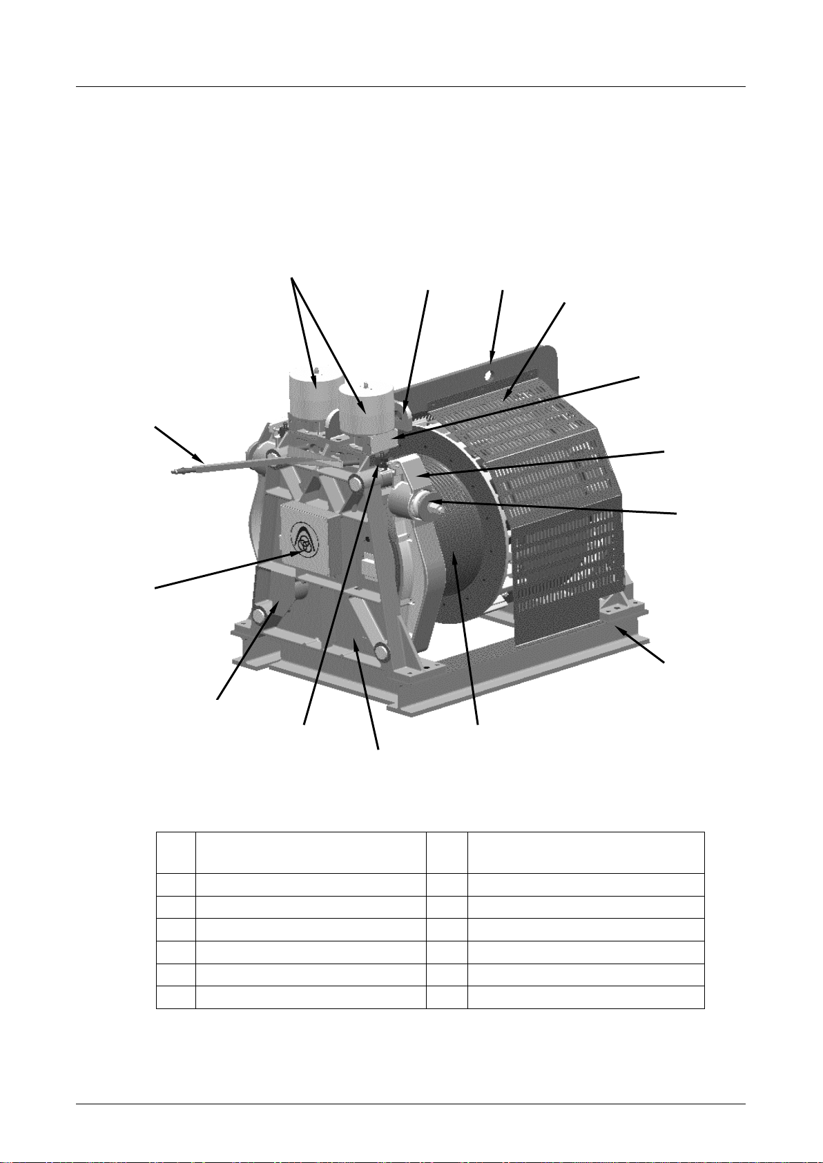
The DAB530 may only be operated in an enclosed machine room and only
with the screen fitted.
Before mounting the manual drive, the power to the drive must be
disconnected and the installation secured against inadvertent activation.
Remove the manual drive before reconnection and screw on the cover plate.
It must be ensured when persons are in the machine room that there is
adequate safety clearance to all revolving (marked in yellow) parts.
In the event of improper use, there is a risk of personal injury or to the life of
the user or third parties, or impairment on the assembly or other assets can
arise.
Malfunctions that can impair safety must be rectified immediately.
ThyssenKrupp Aufzugswerke GmbH
9
Version 03/2017

OPERATING MANUAL DAB530 PRODUCT DESCRIPTION
2. Product description
2.1 Description
1 Brake magnet 8 Transport / machine base
frame
2
Transport eyebolt
9
Traction sheave
3
Transport eyebolt / shackle
10
Name plate
4
Cover grate
11
Brake test switch
5
Brake connection box
12
Mounting for manual drive
6
Brake shoe
13
Motor terminal box
7
Spring plate
14
Brake release lever
7
Fig. 2.1
2
3
8
5
6
1
4
9
10
11
13
12
14
ThyssenKrupp Aufzugswerke GmbH
10
Version 03/2017

OPERATING MANUAL DAB530 PRODUCT DESCRIPTION
Versions
The following different versions can be supplied:
1. Elevator speed
2. Version for current regeneration.
3. Diameter of traction sheave ∅700, 740 or 800 mm
4. Machine base frame versions
5. Accessory parts for maintenance / emergency operation.
6. Additional encoder mounting
Special versions, see description in chapter 8
2.2 Functional description
Machine: the DAB530 consists of a frequency-controlled motor similar in
design to B3 (DIN IN 60034) in protection type IP20. It is firmly screw-
connected to a machine base frame.
The standard version of the rope drive is intended for operation with double
rope wrap and operation with 1 : 1 or 2 : 1 suspension.
Speed measurement takes place via a gear-operated pulse encoder (API).
The associated electronic evaluation system (square wave pulse) is also
fitted and connected by a pulse encoder connector. Mounting for an
optionally available second encoder (GWA) is prepared.
The engine shaft and rope pulley are equipped with roller bearings.
There is a possibility to lubricate all bearings.
The traction sheave and brake disc are doubly supported by bearings and
consist of one cast part.
The gearless machine has no automatic interlock.
Brake: an electromagnetically actuated, type-approved, dual-circuit outer
shoe brake is mounted at the pedestal bearing.
Two brake shoes acting independently of each other press the brake lining
onto the brake disc with pre-adjusted spring force.
The braking force is configured in such a way that one of the brake shoes is
sufficient to bring a loaded elevator car to a standstill.
The position of the brake shoes and the wear of the brake linings is
monitored by test switches. In the event of a malfunction, or when the preset
wear limit has been reached, the test switches switch the drive off.
The brake is released by a separate electromagnet for each brake shoes with
integrated overvoltage protection.
For manual operation, an external brake release lever is fitted. It can be used
to operate one brake shoe or both brake shoes simultaneously.
The DAB530 is self-ventilating. It is configured for thermal class F and is
used according to class B.
The temperature (max. 130 °C ± 5 °C) is monitored.
The maximum sound pressure level is 70 dB(A)
ThyssenKrupp Aufzugswerke GmbH
11
Version 03/2017

OPERATING MANUAL DAB530 PRODUCT DESCRIPTION
Machine base frame: the gearless is delivered with a mounted machine
base frame as a unit. (With double wrap, including built-in rope pulley (DW))
More details on the machine base frame and its dimensions, see chapter 3.
Accessories: The accessories necessary for the operation, maintenance
work and removal of malfunctions such as the hoist, hydraulic cylinder, rope
clamp and manual drive are supplied as options.
If a number of the same machines are set up in one machine room, only one
of each accessory part is required for each room.
Note: A description of specified use is provided in chapter 9.
The machine typ comply with the European standard EN81-1:1998+A3:2009
as well as EN81-20/50:2014 and also the specifications of ASME A17.1.
They comply with the European standard EN60034. Approval for the North
American region (CSA and ASME A17.5) is also available.
2.3 Protection devices for deployment in an earthquake region of
category 1 complying with EN81-77 - optional - (only for delivery with
machine base frame)
Fig. 2-1: DAB external rotor gearless with earthquake protection devices
(the version DAB450S/L is shown)
1
DAB450 external rotor gearless
2
DW-R machine base frame
3
Earthquake protection for traction
sheave
4
Earthquake protection for rope
pulley
5
Shift protection
6
Intrusion protection on rope pulley
ThyssenKrupp Aufzugswerke GmbH
12
Version 03/2017

OPERATING MANUAL DAB530 PRODUCT DESCRIPTION
The protection devices consist of a traction sheave cover, rope holder on the rope
pulley as well as shift protection on the machine base frame. The earthquake
protection device is standardised with traction sheave diameter DT = 700/740/800 mm
and rope pulley diameter = 700.
The intrusion protection meets the requirements from EN81-1/ 9.7 and EN81-20/5.5.7.
Fig. 2-2: Components for earthquake protection on the traction sheave
The traction sheave cover is suitable for SW application as well as DW application.
Rope departures of 0° to 75° to the horizontal can be covered.
The earthquake protection on the traction sheave of the DAB530 is adequately
dimensioned and can be used up to and including earthquake category 2 complying
with EN81-77
Fig. 2-3: Components for earthquake protection on the rope pulley
1
DW-R machine base frame
2
DW rope pulley, diameter 700 mm
3
SW rope holder
4
SW cross strut
5
DW rope guard
ThyssenKrupp Aufzugswerke GmbH
13
Version 03/2017

OPERATING MANUAL DAB530 PRODUCT DESCRIPTION
The earthquake protection on the rope pulley consists of up to 3 different holding-down
clamps.
The holding-down clamps on the DAB530 rope pulley can be used for the ASL range of
1100 - 1500 mm.
All holding-down clamps are adjustable.
The earthquake protection on the rope pulley of the DAB530 is adequately
dimensioned and can be used up to and including earthquake category 2 complying
with EN81-77
Fig. 2-4: Components for earthquake protection on the shift protection on the
machine base frame
Description of items for Fig. 2-5
1
Shift protection adapter
2
DW-R machine base frame
The shift protection ensures that the drive with machine base frame does not change
its position in the event of an earthquake.
The earthquake protection against shifting of the DAB530 is adequately dimensioned
and can be used up to and including earthquake category 1 complying with EN81-77
In the case of deployment of the machine in earthquake categories 2 and 3, additional
safeguard measures in accordance with EN81-77 are necessary.
ThyssenKrupp Aufzugswerke GmbH
14
Version 03/2017

OPERATING MANUAL DAB530 TECHNOLOGY
3. Technology
3.1 Technical data
Power output
The rating of the DAB530 can be found on the type plate
Torques DAB530 L/XL
Braking torque with lifting magnet GH112 009 max. 7 500 Nm
min. 6 500 Nm
per brake shoe
Permitted axle load 1)
Traction sheave 450 [kN]
Rope pulley (DW) ∅700 mm 330 [kN]
Traction sheave with integrated brake disc
700 / 740 / 800 mm Rim diameter and 820 mm brake discs
Weight : DAB530 L/XL
Machine: Lapprox. 4 200 kg XL approx. 4 500 kg
Machine base frame with rope pulley (DW) approx. 1460 - 1520 kg
Rope pulley (DW) diameter 700 approx. 580 kg
Technical data for lifting magnets: see type plate on lifting magnets
Note:
The coils of the lifting magnets are connected in series.
Other technical data can be found on the type plate of the product.
1)calculated with ThyssenKrupp Lift Design (TLD)
ThyssenKrupp Aufzugswerke GmbH
15
Version 03/2017

OPERATING MANUAL DAB530 TECHNOLOGY
3.2 Dimensions of machine
DAB000_32203_GER
S 3)
1
Mounting of machine (pedestal
bearing AS and BS) on machine
base frame
2
Mount of protective hood on
machine base frame
3
Center of grafity
S = 182 DAB530L
S= 207 DAB530XL
Fig. 3.1
ThyssenKrupp Aufzugswerke GmbH
16
Version 03/2017

OPERATING MANUAL DAB530 TECHNOLOGY
3.3 Dimensions of machine base frame (optional)
Right-hand design
1
Min. clearance for lifting
2
Vertical measurement to overall
centre of gravity
3
Vertical measurement traction
sheave to rope pulley
"standard (special size)"
4
Project planning dimension x1
depending on traction sheave
diameter DT:
DT = 700 mm →x1 = 285 mm
DT = 740 mm →x1 = 265 mm
DT = 800 mm →x1 = 235 mm
5
ASL
Fig. 3.2
ThyssenKrupp Aufzugswerke GmbH
17
Version 03/2017

OPERATING MANUAL DAB530 TECHNOLOGY
Side view of machine base frame
1
Min. clearance for brake release
lever
When aligning the grooves of the traction sheave to the rope pulley (DW), the grooves
must be arranged with an offset of half the distance from one groove centre to the next.
Example: groove clearance 20 mm offset = 10 mm
Fig. 3.3
ThyssenKrupp Aufzugswerke GmbH
18
Version 03/2017

OPERATING MANUAL DAB530 TECHNOLOGY
3.4 Encoder
A magnetic tape is mounted in the pedestal bearing AS for the regulation and
control of the DAB530. The signals are read with a magnet sensor.
The connection is made via connector.
Installation instructions, see chapter 5
Technical data
SIKO magnetic tape with evaluation unit with 25600 pulses per revolution
(see table)
Encoder for
Encoder type
Magnet sensor with integrated
evaluation unit
Supply voltage UB
Output tracks
Output
Maximum speed of movement,
magnetic tape
Pulses / revolution
Operating temperature range
Type of protection (sensor)
Connection
DAB530 31401 ENG
RS 422
DAB530L/XL
28800
25 m/s
- 10...+ 70 °C
Approx. 100 mm free connection line with 12-pin
round plug
IP 67
5 V DC +/- 10%
SIKO: magnetic tape MB100 with MSK110TH-SK20
Two square wave signals offset by 90°
and their inverse signals
MSK110TH-SK20
Table 3.4.1
Fig. 3.4
ThyssenKrupp Aufzugswerke GmbH
19
Version 03/2017

OPERATING MANUAL DAB530 TECHNOLOGY
1 Magnet sensor MSK110TH with
integrated electronic evaluation system 2 Magnetic tape MB100
3 Coupling connector of the sensor with
pin contacts
Fig. 3.5
ThyssenKrupp Aufzugswerke GmbH
20
Version 03/2017
Table of contents
Other ThyssenKrupp Industrial Equipment manuals
Popular Industrial Equipment manuals by other brands

Premier
Premier 580 COUPLING Installation, Inspection, Operation & Maintenance Guide

Mono Equipment
Mono Equipment METRO Setup and operation instructions

ABB
ABB HT611147 Operation manual

Reflex
Reflex Variomat VG Instructions for use

Siemens
Siemens 3VT9100-8LB00 operating instructions

Jäger
Jäger Z33-D060.62 S15A manual