COVERPRO 62860 Assembly instructions

WARNING! TO PREVENT SERIOUS INJURY: Do
not start or operate any internal combustion
engine inside or near Portable Garage.
Visit our website at: http://www.harborfreight.com
10 F T. X 17 F T.
PORTABLE GARAGE
Owner’s Manual & Safety Instructions
Save This Manual Keep this manual for the safety warnings and precautions, assembly,
operating, inspection, maintenance and cleaning procedures. Write the product’s serial number in the
back of the manual near the assembly diagram (or month and year of purchase if product has no number).
Keep this manual and the receipt in a safe and dry place for future reference. 23c
When unpacking, make sure that the product is intact
and undamaged. If any parts are missing or broken,
please call 1‑888‑866‑5797 as soon as possible.
Copyright©2023 by Harbor Freight Tools®. All rights reserved.
No portion of this manual or any artwork contained herein may be reproduced in
any shape or form without the express written consent of Harbor Freight Tools.
Diagrams within this manual may not be drawn proportionally. Due to continuing
improvements, actual product may differ slightly from the product described herein.
Tools required for assembly and service may not be included.
Read this material before using this product.
Failure to do so can result in serious injury.
SAVE THIS MANUAL.

Table of Contents
Safety ......................................................... 3
Specifications ............................................. 4
Assembly.................................................... 4
Maintenance.............................................. 14
Parts List and Diagram.............................. 18
Warranty .................................................... 20
WARNING SYMBOLS AND DEFINITIONS
This is the safety alert symbol. It is used to alert you to potential
personal injury hazards. Obey all safety messages that
follow this symbol to avoid possible injury or death.
Indicates a hazardous situation which, if not avoided,
will result in death or serious injury.
Indicates a hazardous situation which, if not avoided,
could result in death or serious injury.
Indicates a hazardous situation which, if not avoided,
could result in minor or moderate injury.
Addresses practices not related to personal injury.
WARNING marking concerning Risk
of Eye Injury. Wear ANSI‑approved
safety goggles with side shields.
Read the manual before
assembly and/or use.
WARNING marking concerning
Risk of Head Injury. Wear hard hat
during assembly and service.
WARNING marking concerning Risk
of Hand Injury. Wear heavy‑duty work
gloves during assembly and service.
WARNING marking concerning
Risk of Respiratory Injury.
Operate engine OUTSIDE and far
away from windows, doors, and vents.
Page 2 For technical questions, please call 1-888-866-5797. 62860
SAFETY OPERATION MAINTENANCESETUP
Page 2 For technical questions, please call 1-888-866-5797. 62860

IMPORTANT SAFETY INFORMATION
Read all safety warnings and instructions.
Failure to follow the warnings and instructions may result in serious injury.
Save all warnings and instructions for future reference.
The warnings, precautions, and instructions discussed in this instruction manual cannot cover all possible
conditions and situations that may occur. It must be understood by the operator that common sense
and caution are factors which cannot be built into this product, but must be supplied by the operator.
Assembly Precautions
1. Do not assemble in windy conditions.
2. Assemble and install only on
flat, level, hard surface.
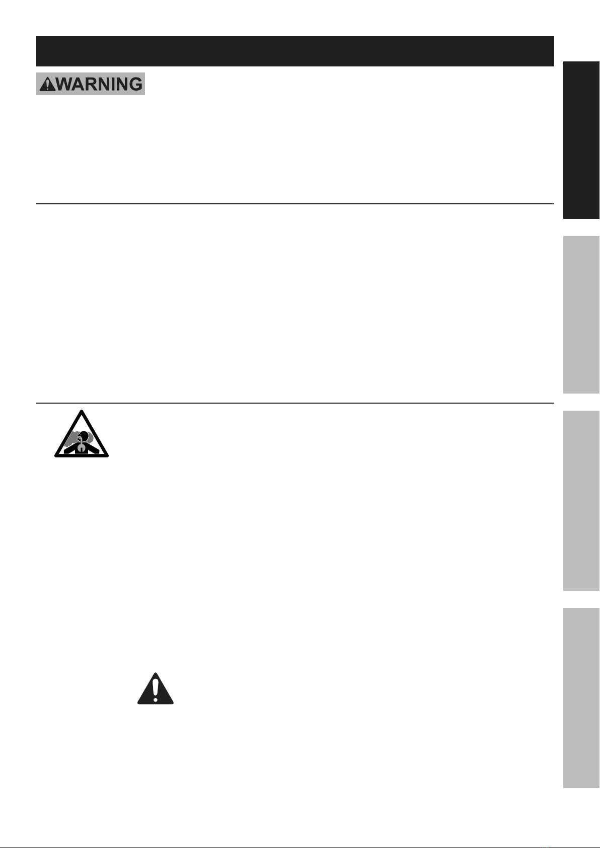
3. Assemble and anchor only according to
these instructions. Improper assembly or
inadequate anchoring can create hazards.
4. Check for utility lines, tree branches and
other structures before assembling.
5. Verify that installation surface has no
hidden utility lines before anchoring.
6. Wear ANSI‑approved safety goggles,
heavy‑duty work gloves and hard hat
during assembly and service.
7. Keep assembly area clean and well lit.
8. Keep bystanders out of the area during assembly.
9. Do not assemble when tired or when under
the influence of drugs or medication.
10. Product capabilities apply to properly and
completely assembled product only.
Use Precautions
1. CARBON MONOXIDE HAZARD
Using an engine inside Shed
CAN KILL YOU IN MINUTES.
Engine exhaust contains
carbon monoxide. This is a poison you cannot see
or smell. NEVER use an engine inside Shed,
EVEN IF cover is open. Only use an engine
OUTSIDE and far away from Shed.
2. DO NOT USE IN HIGH WIND. Remove cover
if harsh weather or heavy rain threatens.
3. For temporary use only.
Do not use for long-term shelter.
4. Do not use as tent. Does not meet tent
flammability standards. Do not use grill, heater,
or ignition sources inside or near cover.
5. Do not allow snow, rainwater or debris
to accumulate or pool on cover.
6. Do not hang objects from any part of the Garage.
7. This product is not a toy. Do not allow
children to play with or near this item.
8. Use as intended only.
9. Inspect regularly, tighten all loose hardware
and loose straps, and secure all loosened
anchors. If any parts are damaged, bent, or
stretched, they must be replaced. Hardware
may loosen during normal operation stresses.
Loose hardware or damaged/altered parts will
compromise the structural integrity of this product.
10. Maintain product labels and nameplates.
These carry important safety information.
If unreadable or missing, contact
Harbor Freight Tools for a replacement.
SAVE THESE INSTRUCTIONS.
Page 3For technical questions, please call 1-888-866-5797.62860
SAFETYOPERATIONMAINTENANCE SETUP
Page 3For technical questions, please call 1-888-866-5797.62860

Specifications
Overall Dimensions 10′ W x 17′ L x 9′ 2" H
Center Height 9′ 2"
Side Height 6′ 5"
Pole Tubing Diameter 1.27"
Assembly
Read the ENTIRE IMPORTANT SAFETY INFORMATION section at the beginning of this
manual including all text under subheadings therein before set up or use of this product.
Note: For additional information regarding the parts listed in the following
pages, refer to Parts List and Diagram on page 18.
TO PREVENT SERIOUS INJURY:
Do not leave this product partially assembled. Assemble this product completely at one time.
Note: At least 3 workers are required for assembly. Before starting assembly, review the instructions and make
sure there is enough time and the proper tools available to properly assemble.
Finger tighten all connections until assembly is done. Assemble on a flat, level surface.
Frame Assembly Overview
A
A
B
A2
A2
A1
B1
1
2
2
3
4
5
6
A
A
B
A2
A2
A1
B1
B1
B1
11
1
2
2
2
320
20
20
20
3
3
3
3
3
3
3
3
4
4
4
4
4
4
20
4
5
5
5
5
5
6
6
6
6
7
7
7
7
9
9
9
9
2
10
10
10
11-1
11-2
11-3
7
1
12
13
10
4
4
20
4A1
Page 4 For technical questions, please call 1-888-866-5797. 62860
SAFETY OPERATION MAINTENANCESETUP
Page 4 For technical questions, please call 1-888-866-5797. 62860

Roof Frame Assembly
Note: Much of this product’s assembly uses slip fit construction. Nut and Bolt connections are required during
proper assembly. Line up all holes on tubes and connectors. Insert Bolt through hole and secure with Nut
installed on the other end. Make sure all parts seat completely and securely. A rubber mallet (sold separately)
can be used to gently tap parts in place to ensure a tight fit. Do not tighten Nuts on the Bolts for the
front and rear tubes. They will need to be removed to install the front and rear canopy walls.
A1 4
3
A2
B1
B
A
A1
B1
B1 B1 A2
A
B
4
4 4
44
44
4
3
3
3
3
333
Figure A: Roof Assembly Overview
1. Assemble ridge using three Rails (4) with
4‑Way Ridge Connectors (B) between them, and
a 3‑Way Ridge Connector (A) on each end. Align
holes and insert six M8x45 Round Head Bolts (20)
and secure with Wing Nut. Ends of the Connectors
should angle downward, as shown in Figure B.
AB
4A
A
B4
4
20
4
2. Connect a Rafter (3) to each end of every Connector
(A, B), align holes and insert eight M8x45 Round
Head Bolt (20) and secure with Wing Nut.
Figure B: Ridge Assembly
AB A
A
B
3
3
20
3
3
3
Figure C: Rafter Assembly
Page 5For technical questions, please call 1-888-866-5797.62860
SAFETYOPERATIONMAINTENANCE SETUP

3. Assemble a roof side rail using a 3‑Way
Side Connector B (A2), three Rails (4) with
4‑Way Side Connectors (B1) between them,
and then a 3‑Way Side Connector A (A1) on the
other end (see Figure D). Align holes and insert
six M8x45 Round Head Bolts (20) and secure
with Wing Nut for all Side Connectors. The Rails
connect to the straight ends of the Connectors,
and the curved ends of all Connectors must
face up angled the same direction, as shown. If
that is not the case, incorrect connectors were
used, or they were assembled backwards.
A1
A1
A2
4
420
B1
B1
4
4
Figure D: Roof Side Rail Assembly
4. Assemble a second identical roof side rail
by repeating the instructions in step #3.
5. Connect the roof side rail assemblies to the ends of
the Rafters (3), align holes and insert eight M8x45
Round Head Bolts (20) and secure with Wing Nut
for all Side Connectors as shown in Figure E.
A1
A2
4
B1
B1
4
4
3
3
3
3
A2
B1
B1
A1
4
20
A2
3
Figure E: Roof Side Rail Installation
6. Make sure all parts assembled up to this
point are firmly joined together.
Page 6 For technical questions, please call 1-888-866-5797. 62860
SAFETY OPERATION MAINTENANCESETUP

Foot, Leg, and Stud Assembly
1. Assemble a Foot (7) to the bottom
of each Center Stud (1):
a. Place a Foot onto the bottom of the Center Stud.
7
1
b. Align the holes and insert one Hex
Head Bolt (12) through them.
12
1
c. Secure with Nut (12).
1
12
7
d. Repeat steps above for remaining
three Center Studs.
2. Attach Corner Leg (6) to the bottom
of each Corner Stud (2):
a. Align holes and insert one M8x45
Round Head Bolt (20) and secure with
Wing Nut as shown in Figure F.
2
6
20
Figure F: Corner Leg Assembly
b. Repeat steps above for remaining Corner Studs.
Page 7For technical questions, please call 1-888-866-5797.62860
SAFETYOPERATIONMAINTENANCE SETUP

Stud Installation
1. With assistance, raise one side of the roof assembly.
2. Install the Center Studs (1) into the 4‑Way Side Connectors (B1), and the Corner Studs (2) into the 3‑Way
Side Connectors A/B (A1, A2) with the Corner Legs (6) facing inward. Align holes and insert four M8x45
Round Head Bolts (20) and secure with Wing Nut as shown in Figure G. Do not tighten nuts on the bolts
for the front and rear tubes. They will need to be removed to install the front and rear canopy walls.
A2
2
1
6
B1
A1
A1
B1
2
2
1
6
20
Figure G: Stud Installation
3. After all four Studs (1, 2) are in place,
rest that side of the assembly on the
ground, and raise the other side.
4. Install four Studs on the other side of the
roof, as explained in step #2, above.
A
B
A2
A1
B1
1
2
3
4
6
A
B
A2
A1
B1
B1
B1
11
1
2
2
2
3
3
3
3
3
3
3
4
4
4
4
4
4
4
4
6
6
6
Figure H: Studs Installed on Both Sides.
5. Make sure all parts assembled up to this point are firmly joined together.
Page 8 For technical questions, please call 1-888-866-5797. 62860
SAFETY OPERATION MAINTENANCESETUP

Anchoring Frame
TO PREVENT SERIOUS INJURY: Contact local utility companies to ensure that the installation area is
free of pipes, cables, and other hazards BEFORE installing anchors or choosing installation area.
1. Position the frame in the desired installation location.
The location must be flat, level, and stable
with good locations for the Anchors (11‑1).
2. Level the frame end‑to‑end and side‑to‑side.
3. Measure the width of the frame at front and back; it
should be 10′ 2" wide.
The distance diagonally in one direction should
be equal to the distance diagonally in the other
direction.
If any measurements do not match, adjust the
frame and retake measurements until they
are equal within a reasonable tolerance.
Note: If measurements cannot be made correct,
then parts may not be seated together properly.
α
α
10′2"
10′2"
Figure I: Verify and Adjust Frame Measurements
4. Once the frame is positioned, leveled, and squared,
anchor the four Corner Legs (6) as follows:
a. Thread the Anchor (11‑1) into the ground near
the Corner Leg until the top of the Anchor
only extends about 3″ above the ground.
Note: Verify that there are no utility lines nearby
before driving anchors. If there are rocks
or other obstacles, holes may need to be
drilled first to allow proper anchoring.
Note: When anchoring frame on concrete, use
Concrete Anchor (19) in place of Anchor.
b. Insert a Cable (11‑2) through the anchor
and through the Corner Leg, as shown.
c. Pull the Cable tight and secure it using a
Cable Clamp (11‑3). Tighten the two nuts on
the Cable Clamp evenly to secure the Cable.
d. Repeat for all three remaining
Anchors and Corner Legs.
6
11-2
11-3
11-1
Figure J: Anchoring
Page 9For technical questions, please call 1-888-866-5797.62860
SAFETYOPERATIONMAINTENANCE SETUP

Securing Ratchet Tie-Downs
Note: Use these instructions for installing
Door, Back, and Roof Cover.
1. Thread the strap through the Ratchet’s (8)
spindle as far as it will go.
Figure K: Threading Strap through Spindle
2. Insert the S‑hook of the Ratchet into
the hole in the Corner Leg (6).
Figure L: Inserting Hook into Corner Leg
3. Lift and lower the Ratchet’s handle to wind
and tighten the strap onto the spindle.
Figure M: Tightening Ratchet
NOTICE: Excessive tightening will damage
straps, Covers, and Corner Legs.
Releasing Ratchet Tie-Downs
1. Depress the spring‑loaded bar on the handle.
2. Open Ratchet handle completely.
3. Unwind the strap.
Figure N: Releasing Ratchet
Page 10 For technical questions, please call 1-888-866-5797. 62860
SAFETY OPERATION MAINTENANCESETUP

Door and Back Cover Installation
Note: When installing Door and Back Cover, ensure
that pre-installed straps are not pulled out of Hem.
1. Position the Door Cover (16) near where you want
the front of the Portable Garage, and turn it so
that the zipper faces the outside of the Portable
Garage, and the warning tag faces inside.
2. Disconnect the Rail (4) from the
3‑Way Ridge Connector (A), and place the
gap at the top center of the Door Cover around
the Ridge Connector, as shown Figure O.
Note that the Door Cover’s flaps wrap
around the Rafters (3), and the strap is
positioned inside the frame. DO NOT ATTEMPT
TO INSERT ANY FRAMEWORK TUBING
INTO THE HEM ON THE COVER FLAPS.
4
Place strap
and flaps
inside frame.
3
A
4
Hem on
Cover flap.
A2
A1
A
Figure O: Door Cover Installation
3. Reconnect the Rail securely to the
3‑Way Ridge Connector.
4. Repeat step #2 for the
3‑Way Side Connectors A/B (A1, A2)
so that the Door Cover looks as shown
in Figure O and Figure P.
Zipper
Figure P: Wrap Around Side Connectors
5. Use two Ratchet Tie‑Downs (8) to attach the
Door Cover to the Corner Legs (6); see Securing
Ratchet Tie‑Downs on page 10 and Figure Q.
8
6
Figure Q: Securing Door Cover
6. Repeat steps #1 – 5 above to install the Back
Cover (17) to the other end of the Portable Garage.
Page 11For technical questions, please call 1-888-866-5797.62860
SAFETYOPERATIONMAINTENANCE SETUP

Roof Cover Installation
1. Lay the Roof Cover (15) on the ground, next to
the frame, so that the three inside pockets for the
opposite side are facing up as shown in Figure R.
2. Slide two Bottom Rails (5) into the
middle openings of the pocket.
3. Tie a rope(sold separately) to each Bottom Rail.
Roof
Cover
(15)
Bottom
Rails
(5)
Pocket
Rope
Rope
Figure R: Align Roof Cover with Frame
4. Throw the ropes over the top of
the frame to the other side.
5. From the other side, pull the ropes to properly
position the Roof Cover as shown in Figure S.
6. Remove the ropes and Bottom Rails.
Figure S: Position Top Cover
Page 12 For technical questions, please call 1-888-866-5797. 62860
SAFETY OPERATION MAINTENANCESETUP

7. After installing roof cover, insert three Bottom
Rails (5) into the fabric tubes on each side
of the Roof Cover as shown in Figure T.
15
5
Figure T: Insert Bottom Rails
8. Make sure the Bottom Rails are level and
horizontal as shown in Figure U.
Bottom Rails (5)
Figure U: Bottom Rails in place.
9. Attach Bottom Rails to the Corner Studs (2)
using 3‑Way End Rail Clamps (9), Bolts
and Nuts (13), and to the Center Studs (1)
with 4‑Way Center Rail Clamps (10),
as shown in Figure V.
13
10
13
9
Figure V: 3- and 4-Way Rail Clamp Connections
Note: Only finger tighten the Nuts at this point.
10. Make sure that all the Bottom Rails are of the same
height from the ground, then tighten all Nuts.
11. Secure the four corners of Roof Cover to the
Corner Legs (6) using Ratchet Tie‑Downs (8); see
Securing Ratchet Tie‑Downs on page 10.
Page 13For technical questions, please call 1-888-866-5797.62860
SAFETYOPERATIONMAINTENANCE SETUP

Maintenance
Procedures not specifically explained in this manual must
be performed only by a qualified technician.
TO PREVENT SERIOUS INJURY FROM PRODUCT FAILURE:
Do not use damaged products. If damage is noted, have the problem corrected before further use.
MONTHLY, inspect the general condition of the Portable Garage. Check for:
• loose ratchet tie downs, anchors, tube connections, and rail clamps (tighten as needed),
• torn or frayed covers, straps, or cables,
• cracked, bent, or broken parts, and
• any other condition that may affect its safe operation.
Page 14 For technical questions, please call 1-888-866-5797. 62860
SAFETY OPERATION MAINTENANCESETUP

Cleaning
1. Immediately remove any accumulated
debris from the cover with a broom, mop,
or other soft‑sided instrument from the
outside. DO NOT use sharp instruments.
2. PERIODICALLY, clean cover with mild
soap and water. DO NOT use bleach
or harsh abrasive products.
Page 15For technical questions, please call 1-888-866-5797.62860
SAFETYOPERATIONMAINTENANCE SETUP

Record Product’s Serial Number Here:
Note: If product has no serial number, record month and year of purchase instead.
Note: Some parts are listed and shown for illustration purposes only, and are not available
individually as replacement parts. Specify UPC 193175507211 when ordering parts.
Page 16 For technical questions, please call 1-888-866-5797. 62860
SAFETY OPERATION MAINTENANCESETUP

PLEASE READ THE FOLLOWING CAREFULLY
THE MANUFACTURER AND/OR DISTRIBUTOR HAS PROVIDED THE PARTS LIST AND ASSEMBLY DIAGRAM
IN THIS MANUAL AS A REFERENCE TOOL ONLY. NEITHER THE MANUFACTURER OR DISTRIBUTOR
MAKES ANY REPRESENTATION OR WARRANTY OF ANY KIND TO THE BUYER THAT HE OR SHE IS
QUALIFIED TO MAKE ANY REPAIRS TO THE PRODUCT, OR THAT HE OR SHE IS QUALIFIED TO REPLACE
ANY PARTS OF THE PRODUCT. IN FACT, THE MANUFACTURER AND/OR DISTRIBUTOR EXPRESSLY
STATES THAT ALL REPAIRS AND PARTS REPLACEMENTS SHOULD BE UNDERTAKEN BY CERTIFIED AND
LICENSED TECHNICIANS, AND NOT BY THE BUYER. THE BUYER ASSUMES ALL RISK AND LIABILITY
ARISING OUT OF HIS OR HER REPAIRS TO THE ORIGINAL PRODUCT OR REPLACEMENT PARTS
THERETO, OR ARISING OUT OF HIS OR HER INSTALLATION OF REPLACEMENT PARTS THERETO.
Page 17For technical questions, please call 1-888-866-5797.62860

Parts List and Diagram
Parts List
Note: Individual part illustrations not to scale.
Part Description Illustration Qty
A3‑Way Ridge
Connector 2
A1 3‑Way Side
Connector A 2
A2 3‑Way Side
Connector B 2
B4‑Way Ridge
Connector 2
B1 4‑Way Side
Connector 4
1 Center Stud 4
2 Corner Stud 4
3 Rafter 8
4 Rail 9
5 Bottom Rail 6
6 Corner Leg 4
7 Foot 4
8Ratchet Tie‑Down 8
Part Description Illustration Qty
93‑Way End
Rail Clamp 8
10 4‑Way Center
Rail Clamp 8
11‑1 Anchor 4
11‑2 Cable - 1′ (31cm) 4
11‑3 Cable Clamp 4
12 M8x50 Hex
Head Bolt 4
13 M8×50 Round
Head Bolt 12
15 Roof Cover 1
16 Door Cover 1
17 Back Cover 1
19* Concrete Anchor 12
20 M8x45 Round
Head Bolt 48
* Item not shown in assembly instructions.
Page 18 For technical questions, please call 1-888-866-5797. 62860

Assembly Diagram
16
15
8
17
3
20 A20 420
B20 20
4B
20
420 A
20
20
A2
20
20
4
2
20
B1
3
20
3
20
20
20
B1 20 4
3
20
20
A1 20 4
20
3
20
20
20
3
A1
13 513
20 20
20
1
1
13
513
5
13 13
20
3
20
20
A2 20 B1
4
20 4
20 3
20 2
B1
20
4
20
20 20
20
20
211
29
10
10 9
20
6
11-1
11-2
11-3
12
7
12
7
6
5
5
5
9
13
20 13
13 10
10
13 9
6
20
11-2
11-3
11-2
11-1
11-3
11-1
7
12
7
12
11-2
11-1
11-3
6
20
20
Page 19For technical questions, please call 1-888-866-5797.62860

26677 Agoura Road • Calabasas, CA 91302 • 1-888-866-5797
Limited 90 Day Warranty
Harbor Freight Tools Co. makes every effort to assure that its products meet high quality and durability standards,
and warrants to the original purchaser that this product is free from defects in materials and workmanship for the
period of 90 days from the date of purchase. This warranty does not apply to damage due directly or indirectly,
to misuse, abuse, negligence or accidents, repairs or alterations outside our facilities, criminal activity, improper
installation, normal wear and tear, or to lack of maintenance. We shall in no event be liable for death, injuries
to persons or property, or for incidental, contingent, special or consequential damages arising from the use of
our product. Some states do not allow the exclusion or limitation of incidental or consequential damages, so the
above limitation of exclusion may not apply to you. THIS WARRANTY IS EXPRESSLY IN LIEU OF ALL OTHER
WARRANTIES, EXPRESS OR IMPLIED, INCLUDING THE WARRANTIES OF MERCHANTABILITY AND FITNESS.
To take advantage of this warranty, the product or part must be returned to us with transportation charges
prepaid. Proof of purchase date and an explanation of the complaint must accompany the merchandise.
If our inspection verifies the defect, we will either repair or replace the product at our election or we may
elect to refund the purchase price if we cannot readily and quickly provide you with a replacement. We will
return repaired products at our expense, but if we determine there is no defect, or that the defect resulted
from causes not within the scope of our warranty, then you must bear the cost of returning the product.
This warranty gives you specific legal rights and you may also have other rights which vary from state to state.
Table of contents
Other COVERPRO Tent manuals

COVERPRO
COVERPRO 56410 Assembly instructions

COVERPRO
COVERPRO 59699 Assembly instructions

COVERPRO
COVERPRO 59707 Assembly instructions

COVERPRO
COVERPRO 63297 Assembly instructions

COVERPRO
COVERPRO 62899 Assembly instructions

COVERPRO
COVERPRO 56184 Assembly instructions

COVERPRO
COVERPRO 58741 Assembly instructions
Popular Tent manuals by other brands

canvascamp
canvascamp SIBLEY 300 DELUXE Setup instructions

Skandika
Skandika Saturn 4 Setup & maintenance

KING CANOPY
KING CANOPY CSR1020BK Assembly manual

SunnCamp
SunnCamp ULTIMA ASPIRE 260 Erection Instructions

skandika outdoor
skandika outdoor VASTERVIK Setup Instruction

Loap
Loap CAMPA 4 instruction manual