COWELL TDS-100H User manual

Handhold
Handhold
Handhold
Handhold
Ultrasonic
Ultrasonic
Ultrasonic
Ultrasonic
Flow
Flow
Flow
Flow
m
m
m
m
eter
eter
eter
eter
User ’ s Guide
SHANGHAI
SHANGHAI
SHANGHAI
SHANGHAI
COWELL
COWELL
COWELL
COWELL
MACHINERY
MACHINERY
MACHINERY
MACHINERY
CO.,
CO.,
CO.,
CO.,
LTD.
LTD.
LTD.
LTD.

-
2
-
CONTENTS
CONTENTS
CONTENTS
CONTENTS
1.0
1.0
1.0
1.0
INTRODUCTION
INTRODUCTION
INTRODUCTION
INTRODUCTION
.
.
.
.
.
.
.
.
.
.
.
.
.
.
.
.
.
.
.
.
.
.
.
.
.
.
.
.
.
.
.
.
.
.
.
.
.
.
.
.
.
.
.
.
.
.
.
.
.
.
.
.
.
.
.
.
.
.
.
.
.
.
.
.
.
.
.
.
.
.
.
.
.
.
.
.
.
.
.
.
.
.
.
.
.
.
.
.
.
.
.
.
.
.
.
.
.
.
.
.
.
.
.
.
.
.
.
.
.
.
.
.
.
.
.
.
.
.
.
.
.
.
.
.
.
.
.
.
.
.
.
.
.
.
.
.
.
.
.
.
.
.
.
.
.
.
.
.
.
.
.
.
.
.
.
.
.
.
.
.
.
.
.
.
.
.
.
.
.
.
.
.
.
.
.
.
.
.
.
.
.
.
.
.
.
.
.
.
.
.
.
.
.
.
.
.
.
.
.
.
.
.
.
.
.
.
.
.
.
.
.
.
.
.
.
.
.
.
.
.
.
.
.
.
.
.
.
.
.
.
.
.
.
.
.
.
.
.
.
.
.
.
.
.
.
.
.
.
.
.
.
.
.
.
.
.
.
.
.
.
.
.
.
.
.
.
.
.
.
.
.
.
.
.
.
.
.
.
.
.
.
.
.
.
.
.
.
.
.
.
.
.
.
.
.
.
.
.
.
.
.
.
.
.
.
.
.
.
.
.
.
.
.
.
.
.
.
.
.
.
.
.
.
.
.
.
.
.
.
.
.
.
.
.
.
.
.
.
.
.
.
.
.
.
.
.
.
.
.
.
.
.
.
.
.
.
.
.
.
.
.
.
.
.
.
.
.
.
.
.
.
.
.
.
.
.
.
.
.
.
.
.
.
.
.
.
.
.
.
.
.
.
.
.
.
.
.
.
.
.
.
.
.
.
.
.
.
.
.
.
.
.
.
.
.
.
.
.
.
.
.
.
.
.
.
.
.
.
.
.
.
.
.
.
.
.
.
.
.
.
4
4
4
4
1.1 P REFACE .......................................................................................................................................
4
1.2 F E ATURES ....................................................................................................................................
4
1.3 F LOW ME AS UREME NT PRINCIPLE ................................................................................................
4
1.4 P
ART
ID ENT IFIC AT ION ..................................................................................................................
6
1.5 T
Y PIC AL
APPL IC ATIO NS ...............................................................................................................
8
1.6 D
ATA
IN TEGRITY
AND
BU ILT
IN
TIME KE EPE R ...........................................................................
8
1.7 P RO DUCT ID ENT IFIC AT ION ...........................................................................................................
8
1.8 S PE CIFICATIONS ...........................................................................................................................
8
2.0
2.0
2.0
2.0
MEA SUREMENT
MEA SUREMENT
MEA SUREMENT
MEA SUREMENT
.
.
.
.
.
.
.
.
.
.
.
.
.
.
.
.
.
.
.
.
.
.
.
.
.
.
.
.
.
.
.
.
.
.
.
.
.
.
.
.
.
.
.
.
.
.
.
.
.
.
.
.
.
.
.
.
.
.
.
.
.
.
.
.
.
.
.
.
.
.
.
.
.
.
.
.
.
.
.
.
.
.
.
.
.
.
.
.
.
.
.
.
.
.
.
.
.
.
.
.
.
.
.
.
.
.
.
.
.
.
.
.
.
.
.
.
.
.
.
.
.
.
.
.
.
.
.
.
.
.
.
.
.
.
.
.
.
.
.
.
.
.
.
.
.
.
.
.
.
.
.
.
.
.
.
.
.
.
.
.
.
.
.
.
.
.
.
.
.
.
.
.
.
.
.
.
.
.
.
.
.
.
.
.
.
.
.
.
.
.
.
.
.
.
.
.
.
.
.
.
.
.
.
.
.
.
.
.
.
.
.
.
.
.
.
.
.
.
.
.
.
.
.
.
.
.
.
.
.
.
.
.
.
.
.
.
.
.
.
.
.
.
.
.
.
.
.
.
.
.
.
.
.
.
.
.
.
.
.
.
.
.
.
.
.
.
.
.
.
.
.
.
.
.
.
.
.
.
.
.
.
.
.
.
.
.
.
.
.
.
.
.
.
.
.
.
.
.
.
.
.
.
.
.
.
.
.
.
.
.
.
.
.
.
.
.
.
.
.
.
.
.
.
.
.
.
.
.
.
.
.
.
.
.
.
.
.
.
.
.
.
.
.
.
.
.
.
.
.
.
.
.
.
.
.
.
.
.
.
.
.
.
.
.
.
.
.
.
.
.
.
.
.
.
.
.
.
.
.
.
.
.
.
.
.
.
.
.
.
.
.
.
.
.
.
.
.
.
.
.
.
.
.
.
.
.
.
.
.
.
.
.
.
.
.
.
.
.
.
.
.
.
.
.
.
.
.
.
.
.
.
.
.
.
.
.
9
9
9
9
2.1 B U ILT
IN
BA TTERY ......................................................................................................................
9
2.2 P O WER O
N
...................................................................................................................................
9
2.3 K E YPAD .......................................................................................................................................
9
2.4 M
E NU
WIN DO WS ....................................................................................................................... 10
2.5 M
E NU
W
IN DO W
L
IS T
.................................................................................................................11
2.6 S T EPS
T O
CO NFIGURE PA RAME TERS ..........................................................................................11
2.7 T RANS DUCER MO UNTING ALLOCAT ION ....................................................................................12
2.8 T RANS DUCER IN STALLAT IO N .....................................................................................................14
2.8.1 Transducer Spacing ...........................................................................................................14
2.8.2 V Method Installation ........................................................................................................ 14
2.8.3
Z
Method Installation ........................................................................................................ 15
2.8.4 W Method Installation ....................................................................................................... 15
2.9 I N STALLATIO N TE STING .............................................................................................................15
2.9.1 Signal Strength .................................................................................................................. 15
2.9.2 Signal Quality ....................................................................................................................15
2.9.3 Total Transit Time and Delta Time . . . . . . . . . . . . . . . . . . . . . . . . . . . . . . . . . . . . . . . . . . . . . . . . . . . . . . . . . . . . . . . . . . . . . . . . . . . . . . . . . . . 16
2.9.4 Transit Time Ratio .............................................................................................................16
3.0
3.0
3.0
3.0
HOW
HOW
HOW
HOW
TO
TO
TO
TO
CHECK
CHECK
CHECK
CHECK
A ND
A ND
A ND
A ND
SETUP
SETUP
SETUP
SETUP
.
.
.
.
.
.
.
.
.
.
.
.
.
.
.
.
.
.
.
.
.
.
.
.
.
.
.
.
.
.
.
.
.
.
.
.
.
.
.
.
.
.
.
.
.
.
.
.
.
.
.
.
.
.
.
.
.
.
.
.
.
.
.
.
.
.
.
.
.
.
.
.
.
.
.
.
.
.
.
.
.
.
.
.
.
.
.
.
.
.
.
.
.
.
.
.
.
.
.
.
.
.
.
.
.
.
.
.
.
.
.
.
.
.
.
.
.
.
.
.
.
.
.
.
.
.
.
.
.
.
.
.
.
.
.
.
.
.
.
.
.
.
.
.
.
.
.
.
.
.
.
.
.
.
.
.
.
.
.
.
.
.
.
.
.
.
.
.
.
.
.
.
.
.
.
.
.
.
.
.
.
.
.
.
.
.
.
.
.
.
.
.
.
.
.
.
.
.
.
.
.
.
.
.
.
.
.
.
.
.
.
.
.
.
.
.
.
.
.
.
.
.
.
.
.
.
.
.
.
.
.
.
.
.
.
.
.
.
.
.
.
.
.
.
.
.
.
.
.
.
.
.
.
.
.
.
.
.
.
.
.
.
.
.
.
.
.
.
.
.
.
.
.
.
.
.
.
.
.
.
.
.
.
.
.
.
.
.
.
.
.
.
.
.
.
.
.
.
.
.
.
.
.
.
.
.
.
.
.
.
.
.
.
.
.
.
.
.
.
.
.
.
.
.
.
.
.
.
.
.
.
.
.
.
.
.
.
.
.
.
16
16
16
16
3.1 H O W
T O
C HECK
T HE
IN STRUME NT
WORKS
PR O PERLY ............................................................... 16
3.2 H O W
T O
C HECK
T HE L IQUID FLO W
D IRE CTION .......................................................................... 16
3.3 H O W
T O
C HANGE
T HE U NIT
READINGS ...................................................................................... 16
3.4 H O W
T O
S ELECT
A
F LO W
RAT E .................................................................................................. 17
3.5 H O W
T O
USE
T HE
T OTALISER MULT IPLIE R .................................................................................17
3.6 H O W
T O S ET
T HE
T OTALISER FUNCTIONS .................................................................................. 17
3.7 H O W
T O
RESET T OTALISERS .......................................................................................................17
3.8 H O W
T O
RESTORE
T HE
F ACTORY D EFAULTS ..............................................................................17
3.9 H O W
T O
USE
T HE
D AMPE R
T O
S TABILIS E
T HE FLO W
RAT E ........................................................ 17
3.10 H O W
USE
T HE
ZE RO
CUT
O FF FUNCTION ....................................................................................17
3.11 H O W
T O S ET
A
ZE RO PO INT ........................................................................................................17
3.12 H O W
T O
C HANGE
T HE FLO W
RAT E
S CALE
FACTOR ....................................................................18
3.13 H O W
T O S ET
AND
LOCK T HE
PA S SWORD ....................................................................................18
3.14 H O W
T O
USE
T HE
IN BUILT D ATA L OGGER ..................................................................................18
3.15 H O W
T O
USE
T HE
FREQUENC Y OU T PUT .................................................................................... 18
3.16 H O W
T O
USE
T HE
T OTALISER P
ULS E
O UTPUT ............................................................................ 19
3.17 H O W
T O
PR ODUCE
AN
A LARM
S IGNAL .......................................................................................19
3.18 H O W
T O
USE
T HE
B UILT
IN
BU ZZE R ...........................................................................................19
3.19 H O W
T O
USE
T HE
OCT P
ULS E
O UTPUT ..................................................................................... 19
3.20 H O W
T O S ET
T HE
B UILT
IN
CA LE NDER ...................................................................................... 20
3.21 H O W
T O
A DJ US T
T HE
LCD C ONTRAST .......................................................................................20
3.22 H O W
T O
USE
T HE
RS232 S ERIAL IN TERFAC E .............................................................................20
3.23 H O W
T O
V IEW
T HE
T OTALISERS .................................................................................................20
3.24 H O W
T O
USE
T HE
WORKING
T IMER
............................................................................................20
3.25 H O W
T O
USE
T HE MANUAL
T OTALISER ......................................................................................20
3.26 H O W
T O
C HECK
T HE
SE RIAL N UMBER ....................................................................................... 20
3.27 H O W
T O
C HECK
T HE
B ATTERY
LIFE
........................................................................................... 20

-
3
-
3.28 H O W
T O
C HARGE
T HE
B ATTERY ................................................................................................ 20
4.0
4.0
4.0
4.0
MENU
MENU
MENU
MENU
WINDOW
WINDOW
WINDOW
WINDOW
DETA ILS
DETA ILS
DETA ILS
DETA ILS
.
.
.
.
.
.
.
.
.
.
.
.
.
.
.
.
.
.
.
.
.
.
.
.
.
.
.
.
.
.
.
.
.
.
.
.
.
.
.
.
.
.
.
.
.
.
.
.
.
.
.
.
.
.
.
.
.
.
.
.
.
.
.
.
.
.
.
.
.
.
.
.
.
.
.
.
.
.
.
.
.
.
.
.
.
.
.
.
.
.
.
.
.
.
.
.
.
.
.
.
.
.
.
.
.
.
.
.
.
.
.
.
.
.
.
.
.
.
.
.
.
.
.
.
.
.
.
.
.
.
.
.
.
.
.
.
.
.
.
.
.
.
.
.
.
.
.
.
.
.
.
.
.
.
.
.
.
.
.
.
.
.
.
.
.
.
.
.
.
.
.
.
.
.
.
.
.
.
.
.
.
.
.
.
.
.
.
.
.
.
.
.
.
.
.
.
.
.
.
.
.
.
.
.
.
.
.
.
.
.
.
.
.
.
.
.
.
.
.
.
.
.
.
.
.
.
.
.
.
.
.
.
.
.
.
.
.
.
.
.
.
.
.
.
.
.
.
.
.
.
.
.
.
.
.
.
.
.
.
.
.
.
.
.
.
.
.
.
.
.
.
.
.
.
.
.
.
.
.
.
.
.
.
.
.
.
.
.
.
.
.
.
.
.
.
.
.
.
.
.
.
.
.
.
.
.
.
.
.
.
.
.
.
.
.
.
.
.
.
.
.
.
.
.
.
.
.
.
.
.
.
.
.
.
.
.
.
.
.
.
.
.
.
.
.
.
.
.
.
.
.
.
.
.
.
.
.
.
.
.
.
.
.
.
.
.
.
.
21
21
21
21
5.0
5.0
5.0
5.0
TROUBLE
TROUBLE
TROUBLE
TROUBLE
SHOOTING
SHOOTING
SHOOTING
SHOOTING
.
.
.
.
.
.
.
.
.
.
.
.
.
.
.
.
.
.
.
.
.
.
.
.
.
.
.
.
.
.
.
.
.
.
.
.
.
.
.
.
.
.
.
.
.
.
.
.
.
.
.
.
.
.
.
.
.
.
.
.
.
.
.
.
.
.
.
.
.
.
.
.
.
.
.
.
.
.
.
.
.
.
.
.
.
.
.
.
.
.
.
.
.
.
.
.
.
.
.
.
.
.
.
.
.
.
.
.
.
.
.
.
.
.
.
.
.
.
.
.
.
.
.
.
.
.
.
.
.
.
.
.
.
.
.
.
.
.
.
.
.
.
.
.
.
.
.
.
.
.
.
.
.
.
.
.
.
.
.
.
.
.
.
.
.
.
.
.
.
.
.
.
.
.
.
.
.
.
.
.
.
.
.
.
.
.
.
.
.
.
.
.
.
.
.
.
.
.
.
.
.
.
.
.
.
.
.
.
.
.
.
.
.
.
.
.
.
.
.
.
.
.
.
.
.
.
.
.
.
.
.
.
.
.
.
.
.
.
.
.
.
.
.
.
.
.
.
.
.
.
.
.
.
.
.
.
.
.
.
.
.
.
.
.
.
.
.
.
.
.
.
.
.
.
.
.
.
.
.
.
.
.
.
.
.
.
.
.
.
.
.
.
.
.
.
.
.
.
.
.
.
.
.
.
.
.
.
.
.
.
.
.
.
.
.
.
.
.
.
.
.
.
.
.
.
.
.
.
.
.
.
.
.
.
.
.
.
.
.
.
.
.
.
.
.
.
.
.
.
.
.
.
.
.
.
.
.
.
.
.
.
.
.
.
.
.
.
.
.
.
.
.
.
.
.
.
.
.
.
.
.
.
.
.
.
.
.
.
.
.
.
.
24
24
24
24
5.1 P O WER -
O N
E RRO RS .................................................................................................................... 24
5.2 W O RKING ST ATUS E RRO RS ........................................................................................................25
5.3 O T HER PROBLEMS
AND
SO LUT IONS .......................................................................................... 26
6.0
6.0
6.0
6.0
COMMUNICA TION
COMMUNICA TION
COMMUNICA TION
COMMUNICA TION
PROTOCOL
PROTOCOL
PROTOCOL
PROTOCOL
.
.
.
.
.
.
.
.
.
.
.
.
.
.
.
.
.
.
.
.
.
.
.
.
.
.
.
.
.
.
.
.
.
.
.
.
.
.
.
.
.
.
.
.
.
.
.
.
.
.
.
.
.
.
.
.
.
.
.
.
.
.
.
.
.
.
.
.
.
.
.
.
.
.
.
.
.
.
.
.
.
.
.
.
.
.
.
.
.
.
.
.
.
.
.
.
.
.
.
.
.
.
.
.
.
.
.
.
.
.
.
.
.
.
.
.
.
.
.
.
.
.
.
.
.
.
.
.
.
.
.
.
.
.
.
.
.
.
.
.
.
.
.
.
.
.
.
.
.
.
.
.
.
.
.
.
.
.
.
.
.
.
.
.
.
.
.
.
.
.
.
.
.
.
.
.
.
.
.
.
.
.
.
.
.
.
.
.
.
.
.
.
.
.
.
.
.
.
.
.
.
.
.
.
.
.
.
.
.
.
.
.
.
.
.
.
.
.
.
.
.
.
.
.
.
.
.
.
.
.
.
.
.
.
.
.
.
.
.
.
.
.
.
.
.
.
.
.
.
.
.
.
.
.
.
.
.
.
.
.
.
.
.
.
.
.
.
.
.
.
.
.
.
.
.
.
.
.
.
.
.
.
.
.
.
.
.
.
.
.
.
.
.
.
.
.
.
.
.
.
.
.
.
.
.
.
.
.
.
.
.
.
.
.
.
.
.
.
.
.
.
.
.
.
.
.
.
.
.
.
.
.
26
26
26
26
6.1 RS232 C O NNECTOR P
IN
-
O UT
.....................................................................................................26
6.2 C O MMUNIC ATIO N PRO TOCOL .................................................................................................... 27
6.2.1 Basic Commands ............................................................................................................... 27
6.2.2 Protocol Prefix Usage ....................................................................................................... 29
6.3 T
HE
MC OMMAND
AND
T HE
ASCII C O DES ............................................................................... 30
7.0
7.0
7.0
7.0
WA RRA NTY
WA RRA NTY
WA RRA NTY
WA RRA NTY
A ND
A ND
A ND
A ND
SERVICE
SERVICE
SERVICE
SERVICE
.
.
.
.
.
.
.
.
.
.
.
.
.
.
.
.
.
.
.
.
.
.
.
.
.
.
.
.
.
.
.
.
.
.
.
.
.
.
.
.
.
.
.
.
.
.
.
.
.
.
.
.
.
.
.
.
.
.
.
.
.
.
.
.
.
.
.
.
.
.
.
.
.
.
.
.
.
.
.
.
.
.
.
.
.
.
.
.
.
.
.
.
.
.
.
.
.
.
.
.
.
.
.
.
.
.
.
.
.
.
.
.
.
.
.
.
.
.
.
.
.
.
.
.
.
.
.
.
.
.
.
.
.
.
.
.
.
.
.
.
.
.
.
.
.
.
.
.
.
.
.
.
.
.
.
.
.
.
.
.
.
.
.
.
.
.
.
.
.
.
.
.
.
.
.
.
.
.
.
.
.
.
.
.
.
.
.
.
.
.
.
.
.
.
.
.
.
.
.
.
.
.
.
.
.
.
.
.
.
.
.
.
.
.
.
.
.
.
.
.
.
.
.
.
.
.
.
.
.
.
.
.
.
.
.
.
.
.
.
.
.
.
.
.
.
.
.
.
.
.
.
.
.
.
.
.
.
.
.
.
.
.
.
.
.
.
.
.
.
.
.
.
.
.
.
.
.
.
.
.
.
.
.
.
.
.
.
.
.
.
.
.
.
.
.
.
.
.
.
.
.
.
.
.
.
.
.
.
.
.
.
.
.
.
.
.
.
.
.
.
.
.
.
.
.
.
.
.
.
.
.
.
.
.
.
.
.
.
.
.
.
.
.
.
.
.
.
.
.
.
.
.
.
.
.
.
30
30
30
30
7.1 W A RRANT Y ................................................................................................................................30
7.2 S
E RVICE
..................................................................................................................................... 31
8.0
8.0
8.0
8.0
A PPENDIX
A PPENDIX
A PPENDIX
A PPENDIX
.
.
.
.
.
.
.
.
.
.
.
.
.
.
.
.
.
.
.
.
.
.
.
.
.
.
.
.
.
.
.
.
.
.
.
.
.
.
.
.
.
.
.
.
.
.
.
.
.
.
.
.
.
.
.
.
.
.
.
.
.
.
.
.
.
.
.
.
.
.
.
.
.
.
.
.
.
.
.
.
.
.
.
.
.
.
.
.
.
.
.
.
.
.
.
.
.
.
.
.
.
.
.
.
.
.
.
.
.
.
.
.
.
.
.
.
.
.
.
.
.
.
.
.
.
.
.
.
.
.
.
.
.
.
.
.
.
.
.
.
.
.
.
.
.
.
.
.
.
.
.
.
.
.
.
.
.
.
.
.
.
.
.
.
.
.
.
.
.
.
.
.
.
.
.
.
.
.
.
.
.
.
.
.
.
.
.
.
.
.
.
.
.
.
.
.
.
.
.
.
.
.
.
.
.
.
.
.
.
.
.
.
.
.
.
.
.
.
.
.
.
.
.
.
.
.
.
.
.
.
.
.
.
.
.
.
.
.
.
.
.
.
.
.
.
.
.
.
.
.
.
.
.
.
.
.
.
.
.
.
.
.
.
.
.
.
.
.
.
.
.
.
.
.
.
.
.
.
.
.
.
.
.
.
.
.
.
.
.
.
.
.
.
.
.
.
.
.
.
.
.
.
.
.
.
.
.
.
.
.
.
.
.
.
.
.
.
.
.
.
.
.
.
.
.
.
.
.
.
.
.
.
.
.
.
.
.
.
.
.
.
.
.
.
.
.
.
.
.
.
.
.
.
.
.
.
.
.
.
.
.
.
.
.
.
.
.
.
.
.
.
.
.
.
.
.
.
.
.
.
.
.
.
.
.
.
.
.
.
.
.
.
.
.
.
.
.
.
.
.
.
.
.
.
.
.
.
.
.
.
.
.
.
.
.
.
.
.
.
.
.
.
.
.
.
.
.
.
.
.
.
.
.
.
.
.
.
.
.
.
.
.
.
.
.
.
.
.
.
.
.
.
.
.
.
.
.
.
.
.
.
.
.
.
.
.
.
.
31
31
31
31
8.1 B A TTERY MA INTENANC E
AND
RE PLACEME NT ..........................................................................31
8.2 P
IPE
S
IZE
T
A BLES
...................................................................................................................... 32
8.2.1 Standard Pipe siz e charts for Copper . . . . . . . . . . . . . . . . . . . . . . . . . . . . . . . . . . . . . . . . . . . . . . . . . . . . . . . . . . . . . . . . . . . . . . . . . . . . . . . 32
8.2.2 Standard Pipe siz e charts for PVC . . . . . . . . . . . . . . . . . . . . . . . . . . . . . . . . . . . . . . . . . . . . . . . . . . . . . . . . . . . . . . . . . . . . . . . . . . . . . . . . . . . . 33
8.2.3 Standard Pipe siz e charts for Steel pipe . . . . . . . . . . . . . . . . . . . . . . . . . . . . . . . . . . . . . . . . . . . . . . . . . . . . . . . . . . . . . . . . . . . . . . . . . . . . 34
8.2.4 Standard Pipe siz e charts for Cast Iron Pipe . . . . . . . . . . . . . . . . . . . . . . . . . . . . . . . . . . . . . . . . . . . . . . . . . . . . . . . . . . . . . . . . . . . . 43
8.2.5 Standard Pipe siz e charts for Ductile Iron Pipe . . . . . . . . . . . . . . . . . . . . . . . . . . . . . . . . . . . . . . . . . . . . . . . . . . . . . . . . . . . . . . . 44
8.3 S O UND S
PE ED
T
A BLES
...............................................................................................................45
8.3.1 Sound Speed data
of
solids ................................................................................................ 45
8.3.2 Sound Speed
in
Water ........................................................................................................47
8.3.3 Sound Speed
in
Liquids ..................................................................................................... 48
List
List
List
List
of
of
of
of
figures
figures
figures
figures
F
IG URE
1: T R ANSIT T IME F LOW ME ASUREMENT PR INCIPL E
...........................................................
6
F
IG URE
2: T
OP
PANEL AND F RONT V IEW
......................................................................................
6
F
IG URE
4: K EYPAD
...................................................................................................................
10
F
IG URE
5: P IPE C ONFIGURATION
AND
T RANSDUCER PL ACEMENT
................................................
13
F
IG URE
6: T R ANSDUCER C LAMP
D OWN
.....................................................................................
14
F
IG URE
7: T R ANSDUCER VME T HOD MO U NTION
.........................................................................
14
F
IG URE
8: T R ANSDUCER
Z
ME T HOD MO U NTING
.........................................................................
15
F
IG URE
9: T R ANSDUCER W M ET HOD MO U NTING
.......................................................................
15
F
IG URE
10: RS232 W IRING D IAG RAM
........................................................................................
27

-
4
-
1.0
1.0
1.0
1.0
INTRODUCTION
INTRODUCTION
INTRODUCTION
INTRODUCTION
1.1
1.1
1.1
1.1
Preface
Preface
Preface
Preface
The Teren Instruments T DS -100 H is a battery-powered ultrasonic flow meter with the capability
of a full-size flow meter. It is carefully designed for portability and ease of use.
The T DS -100 H is based on clamp-on transit-time flow measurement principle. It measures the
flow rate of liquid
in
a pipe from outside of the pipe
by
using a pair of ultrasonic transducers. In
general, the liquid should be full
in
the pipe, and should contain very li ttle particles or bubbles.
Examples of applicable liquids are: water (hot water, chill water, city water, sea water, etc.);
sewage; oil (crude oil, lubricating oil, diesel oil, fuel oil, etc.); chemicals (alcohol, acids, etc.);
waste; beverage and liquid food, solvents and other liquids.
Due to the nature of clamp-on technique, the transducer installation is simple and no special
skills or tools are required. Besides, there is no pressure drop, no moving parts, no leaks and
no contamination.
The T DS -100 H utilizes our proprietary technologies such
as
advanced signal processing, low-
voltage transmitting, small signal receiving with self-adapting, and etc. It also incorporates the
latest surface-mounting semiconductors and mini PCB design techniques. The built-in
rechargeable Ni-H battery can work continuously for more than 1 0 hours without recharge .
The T DS -100 H has also a built-in data-logger, which allows storage of 2,000 lines of data. The
stored information can be downloaded to a PC through its RS232 connection port. The TR-
100 H also provides digital output such
as
frequency output or pulsed totaliser output.
1.2
1.2
1.2
1.2
Features
Features
Features
Features
1.3
1.3
1.3
1.3
Flow
Flow
Flow
Flow
Measurement
Measurement
Measurement
Measurement
Principle
Principle
Principle
Principle
The T DS -100 H ultrasonic flow meter is designed to measure the velocity of liquid within a
closed conduit. It uses the well-know transit-time technology. The transducers are a non-
contacting, clamp-on type. They do not block the flow, thus no pressure drop. They are easy to
install and remove.
The T DS -100 H utiliz e
s
a pair of transducers that function
as
both ultrasonic transmitter and
receiver. The transducers are clamped on the outside of a closed pipe at a specific distance
from each other. The transducers can be mounted
in
V- method where the sound transverses
the pipe twice , or W- method where the sound transverses the pipe four times, or
in
Z-m ethod
where the transducers are mounted on opposite sides of the pipe and the sound crosses the
pipe once. The selection of the mounting method
s
depends on pipe and liquid characteristics.
The T DS -100 H operates by alternately transmitting and receiving a frequency-modulated burst
of sound energy between the two transducers and measuring the transit time that
it
takes for
sound to travel between the two transducers. The difference
in
the transit time measured is
± 0.5% of linearity
± 0.2% of repeatability
± 1 % of accuracy at velocity above
0.6ft/s.
± 0.5% when on-site calibration is
available
Bi-directional measurement
4 flow totalizers
Proprietary low-voltage transmission
technology
Wide pipe siz e range
100 P ico -second time measurement
resolution
0.5 second totalizing period
B uilt-in data-logger
Clam-on transducer. Easy to install and to
maintain
Light weight, portable. Main unit 1.2lbs.
Also able to be used for long-term deployment
-
5
-
directly and exactly related to the velocity of the liquid
in
the pipe ,
as
shown
in
the following
f igure.
F
IG URE
1: T R ANSIT T IME F LOW ME ASUREMENT PR INCIPL E
Where
θ is the angle between the sound path and the flow direction
M is the number of times the sound traverses the flow
D is the pipe diameter
Tup is the time for the beam travelling from upstream the transducer to the downstream
transducer
Tdown is the time for the beam travelling from the downstream transducer to the
upstream transducer
Δ T = Tup – Tdown
Part Identification
Down s tream transducer
spacing
flow
Upstream transducer
Tdown
Tup
θ
downup
TT
TMDV
2
sin

-
6
-
F
F
F
F
IG URE
IG URE
IG URE
IG URE
2:
2:
2:
2:
T
T
T
T
OP
OP
OP
OP
PANEL
PANEL
PANEL
PANEL
AND
AND
AND
AND
FRONT
FRONT
FRONT
FRONT
VIEW
VIEW
VIEW
VIEW
Figure
Figure
Figure
Figure
3:
3:
3:
3:
Transduc
Transduc
Transduc
Transduc
ers
ers
ers
ers
and
and
and
and
cables
cables
cables
cables
-
7
-
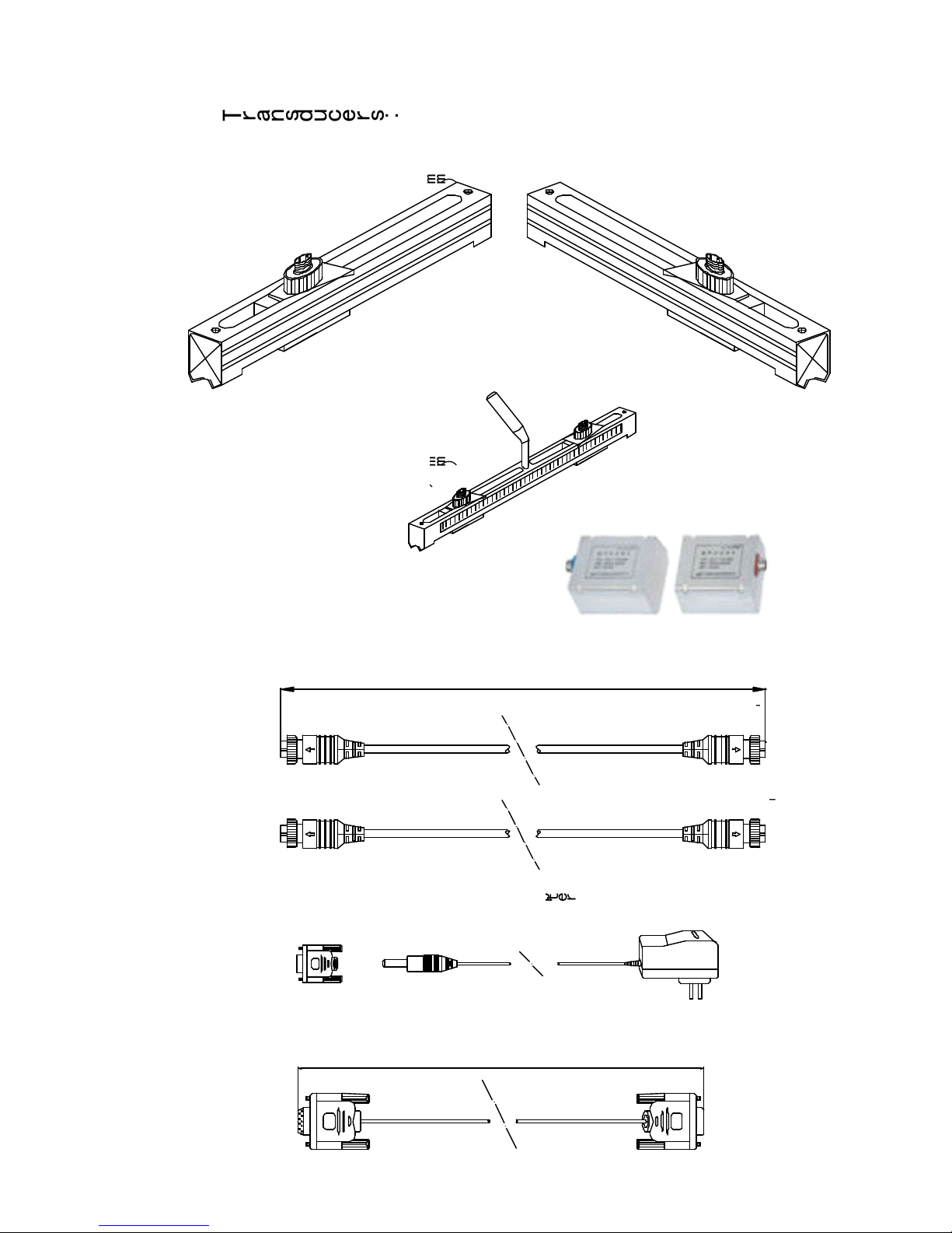
Transducers:
Standard-HM (50mm-700mm)
Cable 5m x2
Blue Terminal
5m
Red Terminal
Blue Terminal
Red Terminal
5m
Red Terminal
Blue Terminal
Blue Terminal
Red Terminal
Standard-HS (20mm-100mm)
(Optional Accessaries)
Extended Cable 5m x2(Optional Accessaries)
M1-type
M1-type
M1-type
M1-type
(2
(2
(2
(2
”
”
”
”
-28
-28
-28
-28
”
”
”
”
)
)
)
)
50-700mm
50-700mm
50-700mm
50-700mm
L1-type
L1-type
L1-type
L1-type
(11
(11
(11
(11
”
”
”
”
-240
-240
-240
-240
”
”
”
”
)
)
)
)
300-6000mm
300-6000mm
300-6000mm
300-6000mm
M-type
M-type
M-type
M-type
(2
(2
(2
(2
”
”
”
”
-28
-28
-28
-28
”
”
”
”
)
)
)
)
50-100mm
50-100mm
50-100mm
50-100mm
S-type
S-type
S-type
S-type
(1/2
(1/2
(1/2
(1/2
”
”
”
”
-4
-4
-4
-4
”
”
”
”
)20-100mm
)20-100mm
)20-100mm
)20-100mm
Converted Terminal and AC/DC Adapter
Cable of RS-232C interface
1m
Converter Terminal and AC adapter
Cable 5metre X 2
Red Terminal
Red Terminal
Blue Terminal
Blue Terminal
Cable_ Rs232 Interface

-
8
-
1.4
1.4
1.4
1.4
Typical
Typical
Typical
Typical
A pplications
A pplications
A pplications
A pplications
The T DS- 100 H flow meter can be applied to a wide range of pipe flow measurements . The
pipe siz e ranges 0.5 ” -240 ” (15mm -6000mm ). A variety of liquid applications can be
accommodated : ultra - pure liquids, potable water, oil, chemicals, raw sewage, reclaimed water,
cooling water, river water, sea water, plant effluent, etc. Because the transducers are non-
contacting and have no moving parts, the flow meter will not be affected
by
flow pressure or
liquid properties. Standard transducers are rated to 100 ºC . Higher temperatures can be
accommodated. For further information, p lease consult the manufacturer for assistance.
1.5
1.5
1.5
1.5
Data
Data
Data
Data
Integrity
Integrity
Integrity
Integrity
and
and
and
and
Built
Built
Built
Built
in
in
in
in
Time
Time
Time
Time
Keeper
Keeper
Keeper
Keeper
A ll user-entered configuration values are stored
in
the built-in n on-volatile flash memory that
can retain the data for over 100 years , even when the power is lost or turned off. Password
protection is provided to avoid inadvertent configuration changes or totalizer resets.
A time-keeper is integrated
in
the flow meter . It works
as
the time base for flow totalizing . The
time-keeper remains operating as long
as
the battery
’
s
terminal voltage is over 1.5V. In case
of battery failure, the time-keeper will not keep running and the time data will lost . The user
must re-enter proper time values after the battery failure is recovered . I mproper time value
s
will affect the totaliz ers
as
well
as
many other functions.
1.6
1.6
1.6
1.6
Product
Product
Product
Product
Identification
Identification
Identification
Identification
Each set of the T DS -100 H
s
eries flow meter has a unique product identification number or
ESN written into the software that can only be modified with a special tool by the manufacturer .
In case of any hardware failure, please provide this number which is located on menu window
M61 when contacting the manufacture r .
1.7
1.7
1.7
1.7
Specifications
Specifications
Specifications
Specifications
Linearity
0.5%
Repeatability
0.2%
Accuracy
± 1% of reading at rates>0.6 ft/s. ± 0.5% with on-site calibration
Response Time
0-999 seconds, user-configurable
Velocity
± 0.03 ~ ± 105 ft/s ( ± 0.01 ~ ± 30 m/s), bi-directional
Pipe Siz e
0.5 ” ~ 240 ” (15 ~ 6,000mm)
Rate Units
Meter, Feet, Cubic Meter, Liter, Cubic Feet, USA Gallon, Imperial
Gallon, Oil Barrel, USA Liquid Barrel, Imperial Liquid Barrel, Million
USA Gallons. User configurable.
Totaliser
7-digit totals for net, positive and negative flow
Liquid Types
Virtually all liquids
Security
Setup lockout. Access code needed for unlocking
Display
4x16 English letters
Communication
Interface
RS-232C, baud-rate: from 75 to 115,200 bps. Protocol made by
the manufacturer. User protocols can be made on enquiry.
Transducers
Model M1 for standard, other 3 models for optional
Transducer
Cable
Standard 2x30
’
(10m), optional 2x1,500
’
(500m)
Power Supply
3 AAA Ni-H built-in batteries. When fully charged
it
will last over 10
hours of operation.
100V-240VAC for the charger
Data Logger
Built-in data logger can store over 2,000 lines of data
Manual Totalizer
7-digit press-key-to-go totalizer for calibration
Housing M aterial
ABS. Aluminum alloy protective case
Case Siz e
3.9"x2.6"x0.8" ( 100x66x20mm)
Handset Weight
1.2 lbs (514g) with batteries

-
9
-
2.0
2.0
2.0
2.0
MEA SUREMENT
MEA SUREMENT
MEA SUREMENT
MEA SUREMENT
2.1
2.1
2.1
2.1
Built
Built
Built
Built
in
in
in
in
Battery
Battery
Battery
Battery
The instrument can operate either from the built-in Ni-H rechargeable battery, which will last
over 10 hours of continuous operation when fully charged, or from an external AC/power
supply from the battery charger.
The battery charging circuit employ
s
both constant-current and constant-voltage charging
methods . It has a characteristic of fast charging at the beginning and very slow charging when
the battery approaches to full charge. Generally, when the green LED is on, the battery is
near ly 95% charged , and when the red LED is off, the battery is nearly 98% charged.
Since the charging current becomes tapered when the battery charg ing is nearly completed,
i.e. the charging current becomes smaller and smaller, therefore, there should be no over-
charging problem. T h is also means the charging progress can last very long. The charger can
be connected to the handset all the time when an around-the-clock measurement is required.
When fully charged, the terminal voltage reaches around 4.25V. The terminal voltage is
displayed on window M07. When the battery is nearly consumed, the battery voltage drops to
below 3V. The approximate remaining working time is indicated
in
this window
as
well.
Notice that the bat tery remaining working time is estimat ed based on the current battery
voltage. It may have some errors, especially when the terminal voltage is
in
the range from
3.70 to -3.90 volt
s
.
For Battery maintenance and replacement, please refer to Appendix A.
2.2
2.2
2.2
2.2
Power
Power
Power
Power
On
On
On
On
Press ON key to turn on the power and press OFF to turn off the power.
Once the flow meter is turned on,
it
will run a self -diagnostic program, checking first the
hardware and then the software integrity. I f there is any abnormality, corresponding error
messages will be display ed .
Generally, there should be no display of error messages, and the flow meter will go to the
most commonly used Menu Window # 01 (short for M01) to display the Velocity, Flow Rate,
Positive Totali
s
er, Signal Strength and Signal Quality, based on the pipe parameters
configured last time by the user or
by
the initial program.
The flow measurement program always operates
in
the background of the user interface. This
means that the flow measurement will keep running regardless of any user menu window
browsing or viewing. Only when the user enters new pipe parameters will the flow meter
change measurement to reflect the new parameter changes.
When new pipe parameters are entered or when the power is turned on, the flow meter will
enter into a self- adjusting mode to adjust the gain of the receiving circuits
so
that the signalstrength will be within a proper range. By this step, theflow meter find
s
the best receiving signal
s
. The user willsee the progress by the number 1 , 2 , or 3, located on thelower right corner of the LCD display.
When the user adjusts the position of the installed
transducers , the flow meter will re-adjust the signal gain
automatically.
Any user-entered configuration value will be stored
in
the
NVRAM (non-volatile memory) , until
it
is modified by the
user.

- 10 -
2.3
2.3
2.3
2.3
Keypad
Keypad
Keypad
Keypad
T he keypad of the flow meter has 16+2 keys .
K
ey
s
0 ~ 9 and . are keys to enter numbers .
K
ey
▲ /+ is the going UP key when the user wants to go
to the upper menu window. It also works
as
+ key when
entering numbers .
K
ey
▼ /- is the going DOWN key when the user wants to
go to the lower menu window. It also works
as
the ‘–‘ key
when entering numbers.
K
ey
◄is the backspace key when the user wants go left
or wants to backspace the left character that is located to
the left of the cursor.
K
ey
ENT is the ENTER key for any input or selection
s
.
K
ey
MENU is the key for the direct menu window jump
over. W henever the user wants to proceed to a certain
menu window, the user can press this key followed by a 2-
digit number.
T he M ENU key is shortened
as
the
‘
M
’
key here after
when referring to menu windows.
The ON key is for the power on.
T he OFF key is for the power off.
F
IG URE
4:
KEYPAD
2.4
2.4
2.4
2.4
Menu
Menu
Menu
Menu
Windows
Windows
Windows
Windows
The user interface of this flow meter comprises about 100 different menu windows that are
numbered by M00, M01, M02 … M99.
There are two methods to get into certain menu window:
(1) Direct jump
in
. The user can press the M ENU key followed
by
a 2- digit number . For
example, the menu window M11 is for setting up pipe outer diameter. Pressing MENU 1 1
will display the M11 menu window immediately .
(2) Press ▲ /+ or ▼ /- key. Each time of the ▲ /+ key pressing will lead to the lower-
numbered menu window. F or example,
if
the current window is on M12, the display will go to
window M11 after the ▲ /+ key is pressed once .
There are three different types of menu windows:
(1) M enu windows for number entering, e.g., M11 for setting up pipe outer diameter.
(2) M enu windows for option selection , e.g., M14 for the selection of pipe materials.
(3) Results display windows, e.g., window M00 for display ing V elocity, Flow Rate , etc.
F or number entering windows, the user can directly press the digit key
s if
the user wants to
modify the value. F or example,
if
the current window is on M11, and the user wants t o enter
219.2345 as the pipe outer diameter , then, the flowing keys should be pressed : 2 1 9 . 2
3 4 5 ENT .
For option selection windows, the user should first press the ENT key to get into option
selection mode . Then, use ▲ /+ ,▼ /- , or digit key to select the right option. Consequently,
press the ENT to make the selection.
For example, assume your pipe material is stainless steel and you are currently on menu
window M14 which is for the selection of pipe material
s
(if you are o n a different window , you
need press MENU 1 4 first
in
order to enter into the M 14 window.) You need to press the
ENT key to get into the option selection mode . T hen , either press the ▲ /+ and ▼ /- keys to
make the cursor on the line that displays “ 1. Stainless Steel ” , or press the 1 key directly. At
the end, press ENT again to make the selection.
Generally, the ENT key must be pressed to get into the option selection mode for option
modifications . I f the “ Locked M47 Open
’
message is indicated on the lowest line of the LCD
display,
it
means that the modification operation is locked out. In such cases, the user should g
ENT
CHARGE
CHARGE
CHARGE
CHARGE
MENU
0
4
7
1
2 3
5
8
6
9
ON OFF

- 11 -
display,
it
means that the modification operation is locked out. In such cases, the user should
go to M47 to have the instrument unlocked before any further modification can be made.
2.5
2.5
2.5
2.5
Menu
Menu
Menu
Menu
Window
Window
Window
Window
List
List
List
List
M 00~M09 windows for the display of the instantaneous flow rate, net totalizer value, positive
totalizer value, negative totalizer value, instantaneous flow velocity, date time, battery voltage
and estimated working hours for the battery.
M10~M29 windows for entering system parameter
s,
such
as
pipe outer diameter, pipe wall
thickness, liquid type, transducer type / model, transducer installation method, etc. Transducer
installation spacing is also displayed on one of the windows. .
M30~M38 windows for flow rate unit selection and totalizer configuration . User can use these
windows to select flow rate unit, such as cubic meter or liter, as well
as
to turn on / off each
totalizer, or to z ero the totalizers.
M40~M49 windows for setting response time, z eroing / calibra ting the system and changing
password.
M50~M53 windows for setting up the built-in logger .
M60-M78 windows for setting up time-keeper and displaying software version , system serial
number ESN and alarms.
M82 window for viewing dat a totaliz er.
M90~M94 windows for displaying diagnostic data. Those data are very useful when doing a
more accurate measurement.
M97~M99 are not windows but commands for window copy output and pipe parameter
output .
M+0~M+8 windows for some additional functions, including a scientific calculator, display of
the total working time , and display of the time and the flow rate when the device is turn ed on
and turn ed off .
O
ther menu windows such
as
M88 have no functions, or functions were cancelled because
they are not applied to this version of the software.
The major reason why the menu windows are arranged
in
th e above way is to make this
version be compatible with previous versions . This will make life easier for the former version
users.
2.6
2.6
2.6
2.6
Steps
Steps
Steps
Steps
to
to
to
to
Configure
Configure
Configure
Configure
Parameters
Parameters
Parameters
Parameters
In order to make the T DS -100 Hwork properly, the user must follow the following steps to
configure the system parameters:
1.
Pipe siz e and pipe wall thickness
2.
For standard pipe, please refer to Appendix B for outer diameter and wall thickness
data. For non-standard pipe, the user has to measure these two parameters.
3. Pipe materials
F or non-standard pipe material, the sound speed of the material must be entered.
Please refer to Appendix C for sound speed data.
4. For standard pipe material
s
and standard liquids , the sound speed values have already
been programmed into the flow meter, therefore there is no need to enter them again.
5.
Liner materia
l,
its sound speed and liner thickness,
if
there is any liner.
6.
L iquid type (for non-standard liquid, the sound speed of the liquid should be entered. )
7. Transducer type .
8. Transducer mounting methods (the V-method and Z-method are the common methods )
9. Check the transducer distance displayed on window M25 and install the transducers
accordingly.
Example: F or standard (commonly used) pipe materials and standard (commonly measured)
liquids, the parameter configuration steps are as following:
(1) Press keys M ENU 1 1 to enter into M11 window . I nput the pipe outer diameter through
the keypad and press ENT key.
(2) Press key ▼ /- to enter into M12 window . I nput the pipe thickness through the keypad and
press ENT key.

- 12 -
(3) Press key ▼ /- to enter into M14 window . P ress ENT key to get into the option selection
mode. Use keys ▲ /+ and ▼ /- to scroll up and down to the proper pipe material, and then
press ENT key.
(4) Press key ▼ /- to enter into M16 window . P ress ENT key to get into the option selection
mode . U
se
keys ▲ /+ and ▼ /- to scroll up and down to the proper liner material, and then
press ENT key. S elect “ No Liner ” ,
if
there is no liner.
(5) Press key ▼ /- to enter into M20 window . P ress ENT key to get into the option selection
mode . U
se
keys ▲ /+ and ▼ /- to scroll up and down to the proper liquid, and then press
ENT key.
(6) Press key ▼ /- to enter into M23 window . P ress ENT key to get into the option selection
mode . Us e keys ▲ /+ and ▼ /- to scroll up and down to the proper transducer type, and then
press ENT key.
(7) Press key ▼ /- to enter into M24 window . P ress ENT key to get into the option selection
mode . U
se
keys ▲ /+ and ▼ /- to scroll up and down to the proper transducer mounting
method, and then press ENT key.
(8) Press key ▼ /- to enter into M 2 5 window . The transducer installation distance will be
displayed on the window. Based on this distance, install the transducers on the pipe now. After
installation is completed , press ENT key to go to M 01 window to check
if
the measurement
result is good .
The first-time users may need some time to get familiar with the operation. However, the user
friendly interface of the instrument makes the operation quite easy and simple. You will soon
find that
it
is actually very quick to configure the instrument with very little key pressing, since
the interface allows the user to go to the desired operation directly without any extra steps.
The following tips will facilitate the operation of this instrument.
(1) When the current window is one between M00 to M09, press ing a number key
x
will enter
into the M0x window directly . F or example,
if
the current window display
i
s
M01, press ing 7
leads to window M07.
(2) When the current window is one between M00 to M09, press ing ENT key will lead to
window M90 for displaying diagnostic data. P ress ENT key again to return to the previous
window . Press the . key to go to window M11 .
When the current window is M25, press ing ENT key will lead to window M01.
2.7
2.7
2.7
2.7
Transducer
Transducer
Transducer
Transducer
Mounting
Mounting
Mounting
Mounting
Allocation
Allocation
Allocation
Allocation
T he first step
in
the installation process is to
s
elect an optim
al
location for installing the
transducers
in
order to make the measurement reliable and accurate . A basic knowledge
about the piping and its plumbing system would be advisable.
An optim
al
location would be defined as a long straight pipe line full of liquid that is to be
measured. T he piping can be
in
vertical or horizontal position. T he following table shows
examples of optim
al
locations.
P rinciples to select an optim
al
location :
1. The straight pipe should be long enough to eliminate irregular-flow-induced error.
Typically, the length of the straight pipe should be 15 times of the pipe diameter. The
longer the better .
The transducers should be installed at a pipe section where the length of the straight
pipe at upstream side is at least 10D and at downstream side is at least 5D. Besides,
the transducer installation site should be at least 30D away from the pump. Here D
stands for pipe outer diameter. Refer to the following table for more details.
2. M ake sure that the pipe is completely full of liquid.
3. Make sure that the temperature on the location does not exceed the range for the
transducers. Generally speaking, the closer to the room temperature, the better.
4. Select a relatively new straight pipe line
if it
is possible . Old pipe tends to have
corrosions and depositions, which could affect the results . I f you have to work on an
ol

- 13 -
old pipe, we recommend you to treat the corrosions and depositions
as
if
they are part
of the pipe wall or
as
part of the liner. For example, you can add an extra value to the
pipe wall thickness parameter or the liner thickness parameter to take into account the
deposition.
5.
S ome pipes may have a kind of plastic liner which creates a certain amount of gaps
between liner and the inner pipe wall. These gaps could prevent ultrasonic waves from
direct travelling . Such conditions will make the measurement very difficult. Whenever
possible, try to avoid this kind of pipes. I f you have to work on this kind of pipe , try our
plug-in transducers that are installed permanently on the pipe
by
drilling holes on the
pipe while liquid is running inside.
F
IG URE
5: P IPE C ONFIGURATION
AND
T RANSDUCER PL ACEMENT

- 14 -
L up L dn
L up
L dn
L up
L up
L up
L dn
L dn
L dn
Piping Configuration
and
Transducer Position
Upstream
Dimension
Downstream
Dimension
L dn
x Diameters
L up
x Diameters
10D
5D
10D
10D
12D
20D
20D
5D
5D
5D
5D
5D
L up
L dn
30D
5D
L up
L dn
Piping Configuration
and
Transducer Position
- 15 -
2.8
2.8
2.8
2.8
Transducer
Transducer
Transducer
Transducer
Installation
Installation
Installation
Installation
The transducers used
by
the TR-100 H series ultrasonic flow meter are made of piezoelectric
crystals both for transmitting and receiving ultrasonic signals through the wall of liquid piping
system. The measurement is realized
by
measuring the travelling time difference of the
ultrasonic signals. Since the difference is very small, the spacing and the alignment of the
transducers are critical factors to the accuracy of the measurement and the performance of the
system. M eticulous care should be taken for the installation of the transducers.
S teps to the installation of the transducers :
Locate an optim
al
position where the straight pipe length is sufficient (see the previous
section) , and where pipes are
in
a favourable condition, e.g., newer pipes with no rust and
ease of operation.
Clean any dust and rust on the spot where the transducers are to be installed. For a better
result, polishing the pipe outer surface with a sander is strongly recommended .
Apply adequate ultrasonic coupl ant (grease, gel or Vaseline)* on to the transducer transmitting
surface
as
well
as
to the installation spot on the pipe surface. Make sure there is no gap
between the transducer transmitting surface and the pipe surface.
E xtra care should be taken to avoid any sand or dust particles left between the pipe surface
and the transducer surface .
F
IG URE
6: T R ANSDUCER C LAMP
D OWN
*Note: It is recommended to use the Conductive Gel product from Livingstone, as the ultrasonic
couplant for safety considerations. Other couplants, such as grease, gel, and Vaseline, can be used as
alternatives, but at your own risk.
2.8.1
2.8.1
2.8.1
2.8.1
Transducer
Transducer
Transducer
Transducer
Spacing
Spacing
Spacing
Spacing
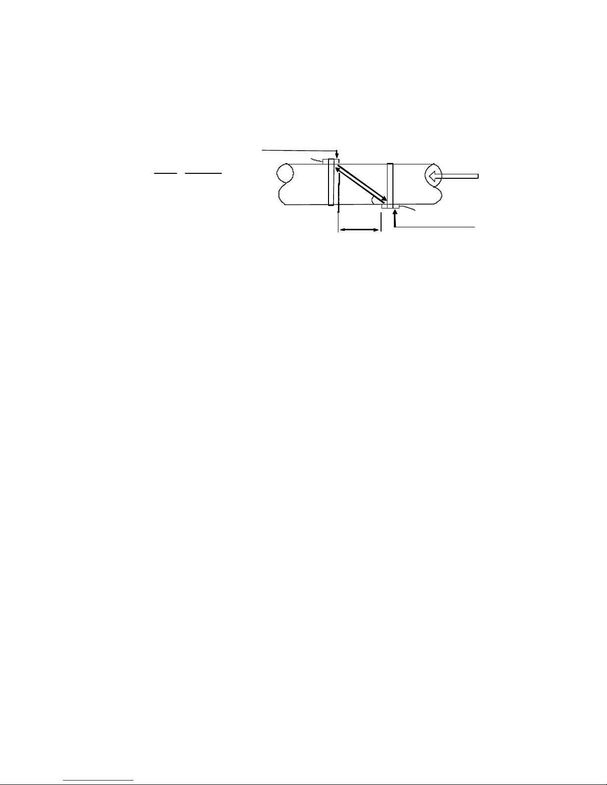
T he spacing value shown on menu window M25 refers to the distance of inner spacing
between the two transducers (see the following figure) . The actual distance of the two
transducers should be as close
as
possible to th is spacing value.
2.8.2
2.8.2
2.8.2
2.8.2
V
V
V
V
Method
Method
Method
Method
Installation
Installation
Installation
Installation
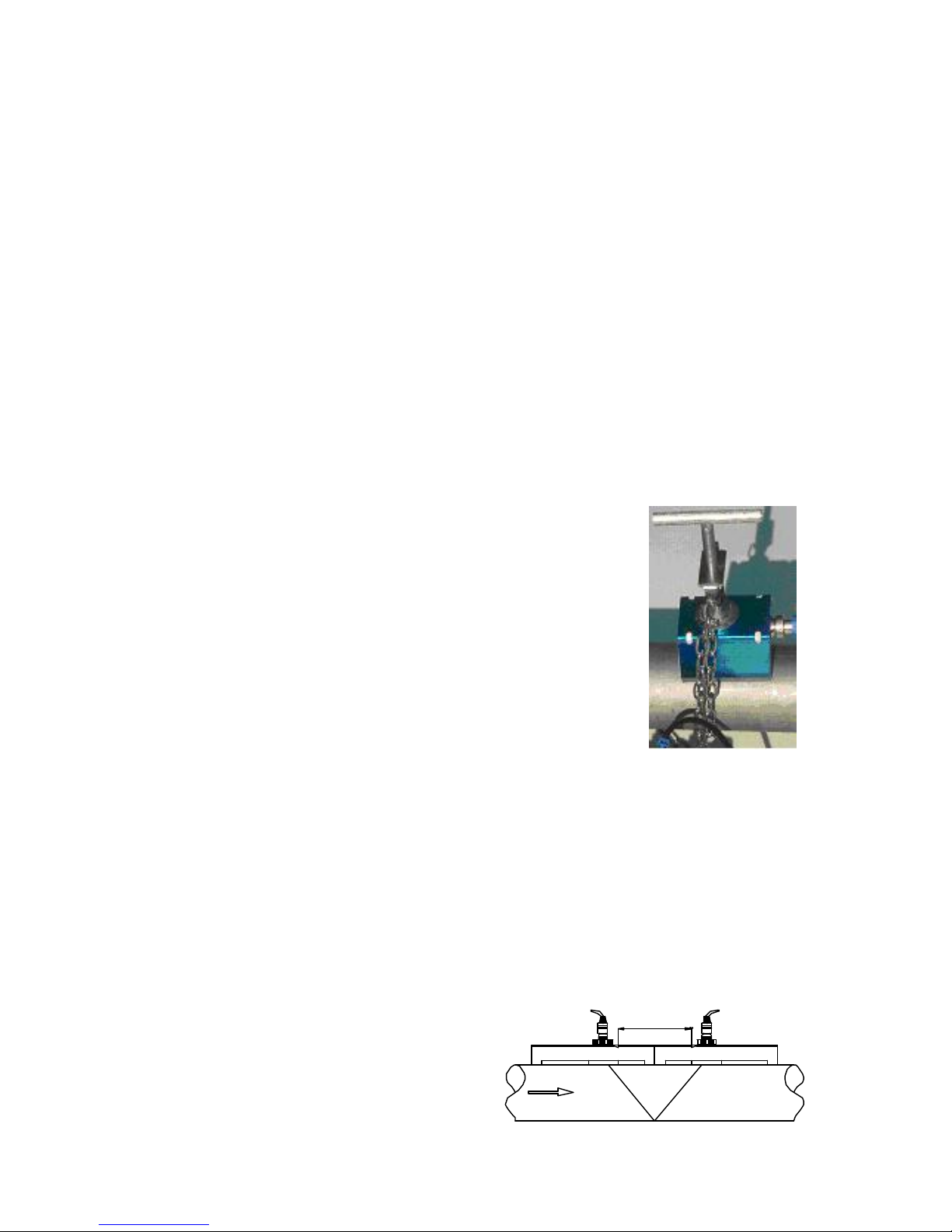
V-method installation is the mos t widely
used method for daily measurement with
pipe inner diameters ranging from 20
millimetres to 300 millimetres . I t is also
called reflective method.
F
IG URE
7: T R ANSDUCER VMET HOD
MO U NTION
Horizontally lined pipes could have gas bubbles inside the upper
part of the pipe . Therefore,
it
is recommended to install the
transducers horiz ontally
by
the side of the pipe.
There are three ways to mount the transducers on the pipe: by
magnetic force,
by
clamp-on fixture and
by
hand. If the pipe
material is metal, the magnetic force will hold the transducer on
the pipe. Otherwise, you may either simply hold the transducer
han dle and press
it
against the pipe (for S-type only)
if
you just
need a quick measurement, or, you may use or a metal strip or
the provided clamp fixture to install the transducers (see the
figure on the right.)
Sensors Spacing
TOP VIEW OF PIPE

- 16 -
2.8.3
2.8.3
2.8.3
2.8.3
Z
Z
Z
Z
Method
Method
Method
Method
Installation
Installation
Installation
Installation
Z-method is commonly used when the
pipe diameter is between 1 00 millimetres
’
and 500 millimetres .
This method is the most direct for signal
transfer and can therefore provide better
results than V method on many
applications.
F
IG URE
8: T R ANSDUCER
Z
MET HOD
MO U NTING
2.8.4
2.8.4
2.8.4
2.8.4
W
W
W
W
Method
Method
Method
Method
Installation
Installation
Installation
Installation
W-method is usually used on plastic
pipes with a diameter from 10 millimetres
to 100 millimetres.
This method can be effective on smaller
pipes that have internal deposits.
F
IG URE
9: T R ANSDUCER W M ETHOD
MO U NTING
2.9
2.9
2.9
2.9
Installation
Installation
Installation
Installation
Testing
Testing
Testing
Testing
After completion of the transducer installation, the user should check the following items : the
receiving signal strength , the signal quality
Q
value, the delta time (traveling time difference
between the upstream and the downstream signals ) , the estimated liquid sound speed, the
transit time ratio, and etc . As such , one can be sure that the flowmeter is working properly and
the results are reliable and accurate.
2.9.1
2.9.1
2.9.1
2.9.1
Signal
Signal
Signal
Signal
Strength
Strength
Strength
Strength
S ignal strength indicates the amplitude of receiving ultrasonic signals
by
a 3-digit number. [000 ]
means there is no signal detected and [999] refers to the maximum signal strength that can
be received.
A lthough the instrument works well when the signal strength ranges from 500 to 999, stronger
signal strength should be pursued, because a stronger signal means a better result. T he
following methods are recommended to obtain strong signals:
(1) I f the current location is not good enough for a stable and reliable flow reading, or
if
the
signal strength is lower than 700 , r elocate to a more favorable location.
(2) Try to polish the outer surface of the pipe, and apply more coupl ant to increase the signal
strength.
(3) Tenderly a djust the position of the two transducer
s,
both vertically and horizontally , while
checking the signal strength . S top at the position where the signal strength reaches to
maximum. T hen , check the transducer spacing to make sure
it
is the same
as
or very close to
what window M25 shows.
2.9.2
2.9.2
2.9.2
2.9.2
Signal
Signal
Signal
Signal
Quality
Quality
Quality
Quality
Signal quality is indicated
as
the
Q
value
in
the instrument. A higher
Q
value would mean a
higher Signal to Noise Ratio (short for SNR), and accordingly a higher degree of accuracy able
TOP VIEW OF PIPE
Sensors Spacing
TOP VIEW OF PIPE
Sensors Spacing

- 17 -
to be achieved. U nder normal pipe condition, the
Q
value is
in
the range of 60-90, the higher
the better.
Causes for a lower
Q
value could be:
1.
Interference from other instruments and devices nearby, such
as
a powe r frequency
transverter which could cause strong interference . T ry to relocate the flow meter to a
new place where the interference can be reduced.
2. Bad sonic coupling between the transducers and the pipe. Try to polish the pipe
surface again, clean the surface and apply more coupl ant , etc.
3. The selected p ipe section is difficult to conduct the measure ment . R elocat e to a more
favourable pipe line.
2.9.3
2.9.3
2.9.3
2.9.3
Total
Total
Total
Total
Transit
Transit
Transit
Transit
Time
Time
Time
Time
and
and
and
and
Delta
Delta
Delta
Delta
Time
Time
Time
Time
T he total transit time (or travelling time) and the delta time are d isplayed on menu window M93 .
They are the primary data for the instrument to calculate the flow rate. Therefore, the
measured flow rate will vary
as
the total transit time and delta time vary .
T he total transit time should remain stable or vary
in
a very small range .
The delta time normally varies less than 20%. If the variation exceeds 20%
in
either positive or
negative direction , there could be certain kinds of problems with the transducer installation.
The user should check the installation for sure.
2.9.4
2.9.4
2.9.4
2.9.4
Transit
Transit
Transit
Transit
Time
Time
Time
Time
Ratio
Ratio
Ratio
Ratio
This ratio is usually used to check whether the transducer installation is good and whether the
entered pipe parameters are
in
consistency with their actual values. If the pipe parameters are
correct and the transducers are installed properly, the transit time ratio should be
in
the range
of 100 ±3. If this range is exceeded, the user should check:
1.
If the entered pipe parameters are correct ?
2.
If the actual spacing of the transducers is the same
as
or close to what shown on
window M25 ?
3. If the transducer are installed properly
in
the right direction?
4. If the mounting location is good ,
i
f the pipe has changed shape , or
if
the pipe is too old
(i.e., too much corrosion or deposition inside the pipe )?
5. If there is any interference source inside of the pipe?
If there are o ther aspects which do not meet the measurement requirements as
recommended before
3.0
3.0
3.0
3.0
HOW
HOW
HOW
HOW
TO
TO
TO
TO
CHECK
CHECK
CHECK
CHECK
AND
AND
AND
AND
SETUP
SETUP
SETUP
SETUP
3.1
3.1
3.1
3.1
How
How
How
How
to
to
to
to
check
check
check
check
the
the
the
the
instrument
instrument
instrument
instrument
works
works
works
works
properly
properly
properly
properly
Generally speaking, w hen
‘
R
’
is displayed
in
the lowe r right corner of the LCD display, the
instrument is working properly.
I f an
‘
H
’
flashes instead , the received signal could be poor. Please refer to the chapter on
diagnosis for more information .
If an
‘
I
’
is displayed,
it
means that there is no signal detected.
I f a
‘
J
’
is displayed,
it
means that the hardware of this instrument could be out of order. R efer
to the chapter on diagnosis.
3.2
3.2
3.2
3.2
How
How
How
How
to
to
to
to
check
check
check
check
the
the
the
the
liquid
liquid
liquid
liquid
flow
flow
flow
flow
direction
direction
direction
direction
Check the flow rate display . I f the value is POSITIVE , the direction of the flow will be
from the RED transducer to the B LUE transducer;
if
the value is NEGATIVE , the
direction will be from the BLUE transducer to the RED transducer.

- 18 -
3.3
3.3
3.3
3.3
How
How
How
How
to
to
to
to
change
change
change
change
the
the
the
the
unit
unit
unit
unit
readings
readings
readings
readings
Use menu window M30 for the selection of unit
s
system
s,
either English or
in
Metric.
3.4
3.4
3.4
3.4
How
How
How
How
to
to
to
to
select
select
select
select
a
a
a
a
flow
flow
flow
flow
rate
rate
rate
rate
Use menu window M31 to select the flow rate unit as well
as
the corresponding tim e unit.
3.5
3.5
3.5
3.5
How
How
How
How
to
to
to
to
use
use
use
use
the
the
the
the
totaliser
totaliser
totaliser
totaliser
multiplier
multiplier
multiplier
multiplier
U
se
window M33 to select a proper multiplying factor for the totalizer multiplier . Make sure that
the rate of the totaliz er pulse is not too fast , neither too slow. A speed of several pulse
s
per
minute is preferable.
I f the totaliz er multipl ying factor is too small, the output pulse will be very fast and there could
be a loss of pulse
s.
T he designed minimum pulse period is 500 milliseconds .
I f the totaliz er multipl ying factor is too large, the output pulse will be very slow, which might be
a problem
if
the master device requires fast response.
3.6
3.6
3.6
3.6
How
How
How
How
to
to
to
to
set
set
set
set
the
the
the
the
totaliser
totaliser
totaliser
totaliser
functions
functions
functions
functions
The flow meter has three totalise functions, generally you will only need the Pos totaliser set
as
most pipes will have flow
in
one direction only.
U
se
M34, M35 and M36 to turn on or turn off the POS, NEG, or NET totaliser, respectively.
3.7
3.7
3.7
3.7
How
How
How
How
to
to
to
to
reset
reset
reset
reset
totalisers
totalisers
totalisers
totalisers
U
se
M37 to reset the flow rate totalisers .
3.8
3.8
3.8
3.8
How
How
How
How
to
to
to
to
restore
restore
restore
restore
the
the
the
the
factory
factory
factory
factory
defaults
defaults
defaults
defaults
Go to window M37 . Press . key followed
by
t he backspace key ◄
Th is operation will erase all the parameters entered by the user and setup the instrument with
factory default values.
3.9
3.9
3.9
3.9
How
How
How
How
to
to
to
to
use
use
use
use
the
the
the
the
damper
damper
damper
damper
to
to
to
to
stabilise
stabilise
stabilise
stabilise
the
the
the
the
flow
flow
flow
flow
rate
rate
rate
rate
T he damper acts as a filter for a stable reading. I f
‘
0
’
is entered
in
window M40, that means
there is no damping. A bigger number brings a more stable effect. B ut bigger damper numbers
will prevent the instrument from acting quickly.
N umbers of 0 to 10 are commonly used for the damper value.
3.10
3.10
3.10
3.10
How
How
How
How
use
use
use
use
the
the
the
the
z ero
z ero
z ero
z ero
cut
cut
cut
cut
off
off
off
off
function
function
function
function
T he number displayed
in
window M41 is called the z ero - cut-off value. When the absolute
value of the measured flow rate is less than the z ero - cut-off value , the measured flow rate will
be replaced with
‘
0
’
. This is to avoid any invalid accumulation when the actual flow is below the
z ero- cut-off value.
T he z ero - cut-off operation does not affect the flow measurement when the actual flow is
greater than the z ero-cut-off value.
3.11
3.11
3.11
3.11
How
How
How
How
to
to
to
to
set
set
set
set
a
a
a
a
z ero
z ero
z ero
z ero
point
point
point
point
W hen the flow
in
a pipe is absolutely stopped , t he flow meter could still give a small non-z ero
flow rate reading. In order to make the measurement accurate,
it
is necessary to remove this “

- 19 -
3.11
3.11
3.11
3.11
How
How
How
How
to
to
to
to
set
set
set
set
a
a
a
a
z ero
z ero
z ero
z ero
point
point
point
point
W hen the flow
in
a pipe is absolutely stopped , t he flow meter could still give a small non-z ero
flow rate reading. In order to make the measurement accurate,
it
is necessary to remove this
“ z ero point ” reading.
Window M 42 allows
us
to take care of this issue. At first, the user should make sure that the
liquid
in
the pipe is totally stopped (no velocity). Then, go to window M42 and press the ENT
key to start the z ero point setup function.
3.12
3.12
3.12
3.12
How
How
How
How
to
to
to
to
change
change
change
change
the
the
the
the
flow
flow
flow
flow
rate
rate
rate
rate
scale
scale
scale
scale
factor
factor
factor
factor
A scale factor (SF) is the ratio between the
‘
actual flow rate
’
and the flow rate measured
by
the
flow meter. It can be determined by calibration with a standard flow calibration equipment. To
change the SF, press M45, then the ENT key , enter the new SF, and press ENT again.
3.13
3.13
3.13
3.13
How
How
How
How
to
to
to
to
set
set
set
set
and
and
and
and
lock
lock
lock
lock
the
the
the
the
password
password
password
password
T he password lock provides a means of preventing inadvertent configuration changes or
totalizer resets.
W hen the system is locked, the user can still browse menu window
s,
but cannot make any
modifications on the windows.
The password locking / unlocking is done
in
window M47. T he system can be locked without a
password or with a password consisted of 1 to 4 digits .
For no-password locking / unlocking , just press ENT key
in
window M47 .
CAUTION!
If the password is forgotten , after being locked no further access will be allowed, please write
down the password and store
in
a safe location .
3.14
3.14
3.14
3.14
How
How
How
How
to
to
to
to
use
use
use
use
the
the
the
the
inbuilt
inbuilt
inbuilt
inbuilt
data
data
data
data
logger
logger
logger
logger
The built-in data logger has a space of 24K bytes of memory, which will hold about 2000 lines
of data.
Use M50 to turn on the logger and to select the items that are going to be logged.
Use M51 to set up the starting time, time interval, and the duration each logging lasts .
Use M 52 to select the data storage direction. Data can be stored
in
a logger buffer or directed
to the RS-232C interface without being stored into the logger buffer.
Use M53 to view the data
in
the logger buffer.
User needs to go to window M52 to clear the logging data remained
in
the RS-232C interface
and
in
the logger buffer.
3.15
3.15
3.15
3.15
How
How
How
How
to
to
to
to
use
use
use
use
the
the
the
the
Frequency
Frequency
Frequency
Frequency
Output
Output
Output
Output
The flowmeter will produce a pulse output with every unit of liquid flow . This pulse could be
used
by
an external pulse counter to accumulate the flow rate.
R efer to § 3.4 and § 3.5 for the setup of the totalizer units and multiplier.
The totalizer pulse output can only be connected to OCT devices or BUZZER hardware
devices.
F or example, assume that the POS totalizer pulse output is needed, and every pulse
represent
s
0.1cubic meter of liquid flow . Assume also that the pulse output is connected to an
internal Buzzer . W
ith
every 0.1 cubic meter of flow , we need the BUZZER to beep for a while. I

- 20 -
internal Buzzer . W
ith
every 0.1 cubic meter of flow , we need the BUZZER to beep for a while.
In order to achieve this, the f ollowing steps must be performed:
Select the Cubic M eter (m3) unit
in
window M 32.
Select the Multiplier factor
as
‘
2. X0.1
’
in
window M 33.
S elect the output option
‘
9. POS INT Pulse
’
in
window M77. (INT stands for totalized )
3.16
3.16
3.16
3.16
How
How
How
How
to
to
to
to
use
use
use
use
the
the
the
the
totaliser
totaliser
totaliser
totaliser
Pulse
Pulse
Pulse
Pulse
output
output
output
output
The flowmeter will produce a pulse output with every unit of liquid flow . This pulse could be
used
by
an external pulse counter to accumulate the flow rate.
R efer to § 3.4 and § 3.5 for the setup of the totalizer units and multiplier.
The totalizer pulse output can only be connected to OCT devices or BUZZER hardware
devices.
F or example, assume that the POS totalizer pulse output is needed, and every pulse
represent
s
0.1cubic meter of liquid flow . Assume also that the pulse output is connected to an
internal Buzzer . W
ith
every 0.1 cubic meter of flow , we need the BUZZER to beep for a while.
In order to achieve this, the f ollowing steps must be performed:
(1)
Select the Cubic M eter (m3) unit
in
window M 32.
(2)
Select the Multiplier factor
as
‘
2. X0.1
’
in
window M 33.
(3)
S elect the output option
‘
9. POS INT Pulse
’
in
window M77. (INT stands for totalized )
3.17
3.17
3.17
3.17
How
How
How
How
to
to
to
to
produce
produce
produce
produce
an
an
an
an
alarm
alarm
alarm
alarm
signal
signal
signal
signal
There are 2 types of hardware alarm signals that are available with this instrument.
O
ne is the
Buz zer, and the other is the OCT output.
T he triggering sources of the alarming event
s
for b oth the Buz zer and the OCT output could
be:
(1)
T here is no receiving signal
(2)
T he signal received is too weak .
(3)
T he flowmeter is not
in
normal measurement modes.
(4)
The flow direction is changed .
(5)
O
verflow occurs at the Frequency Output
(6)
The flow is out of the specified range.
T here are two alarms
in
this instrument , #1 a larm and #2 a larm. T he
y
can be configured
in
windows M73, M74, M75 and M 76.
F or example, assume we need the Buzzer to start beeping when the flow rate is less than 300
m3/h and greater than 2000m3/h . T he following setup steps would be recommended.
(1)
Enter flow rate lower limit 300
in
M73 for #1 alarm ,
(2)
Enter flow rate upper limit 2000
in
M74 for #1 alarm ,
(3)
Select item
‘
6. Alarm #1
’
in
M77.
3.18
3.18
3.18
3.18
How
How
How
How
to
to
to
to
use
use
use
use
the
the
the
the
built
built
built
built
in
in
in
in
Buz zer
Buz zer
Buz zer
Buz zer
T he built-in buzzer is user-configurable. It can be used
as
an alarm. Use M77 for setups.
3.19
3.19
3.19
3.19
How
How
How
How
to
to
to
to
use
use
use
use
the
the
the
the
OCT
OCT
OCT
OCT
Pulse
Pulse
Pulse
Pulse
output
output
output
output
The OCT output is on/off type. It is user-configurable . For example, you can set the OCT
output to be a pulse signal for flow accumulation .
Use M7 7 for the setup.
Notice that the Frequency Output shares the same OCT hardware .
Table of contents
Popular Measuring Instrument manuals by other brands


Frye
Frye FONIX Hearing Evaluator FA-10 Operator's manual

Fluke
Fluke ScopeMeter 123B User manaul

Heyuan Intelligence
Heyuan Intelligence DZ81-MS3UI7E3 user manual

Micronics
Micronics U3000 user manual

KTR-Group
KTR-Group DATAFLEX 42/1000 Operating & assembly instructions

SED flowcontrol
SED flowcontrol 024.63 Series operating instructions


