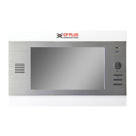
CP Plus ORANGE CP-UVK-711M User manual

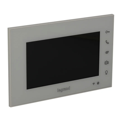
Villa Indoor Monitor
User Manual
Version 2.0.1

Foreword
General
This Quick Start Guide (hereinafter referred to be "the Guide") introduces the functions, installation, and
operations of the camera.
Safety Instructions
The following categorized signal words with defined meaning might appear in the guide.
Signal Words
Meaning
Indicates a medium or low potential hazard which, if not avoided,could
result in slight or moderate injury.
Indicates a potential risk which, if not avoided, may result in property
damage, data loss, lower performance, or unpredictableresult.
Provides additional information as the emphasis and supplementto the
text.
Privacy Protection Notice
As the device user or data controller, you might collect personal data of others' such as face, fingerprints,car plate
number, Email address, phone number, GPS and so on. You need to be in compliance with thelocal privacy
protection laws and regulations to protect the legitimate rights and interests of other people by implementing
measures include but not limited to providing clear and visible identification to inform data subject the existence
of surveillance area and providing related contact.

About this Guide
•The Guide is for reference only. If there is inconsistency between the Guide and the actualproduct,
the actual product shall prevail.
•We are not liable for any loss caused by the operations that do not comply with the Guide.
•The Guide would be updated according to the latest laws and regulations of related regions. Fordetailed
information, see the paper Quick Start Guide, CD-ROM, QR code or our official website.If there is
inconsistency between paper User's Guide and the electronic version, the electronic version shall prevail.
•All the designs and software are subject to change without prior written notice. The product updates
might cause some differences between the actual product and the Guide. Please contactthe customer
service for the latest program and supplementary documentation.
•There still might be deviation in technical data, functions and operations description, or errors inprint. If
there is any doubt or dispute, please refer to our final explanation.
•Upgrade the reader software or try other mainstream reader software if the Guide (in PDF format)cannot
be opened.
•All trademarks, registered trademarks and the company names in the Guide are the properties of their
respective owners.
•Please visit our website, contact the supplier or customer service if there is any problem occurredwhen
using the device.
•If there is any uncertainty or controversy, please refer to our final explanation.

Important Safeguards and Warnings
Electrical safety
•All installation and operation should conform to your local electrical safety codes.
•The power source shall conform to the Safety Extra Low Voltage (SELV) standard, and supply power with
rated voltage which conforms to Limited power Source requirement according to IEC60950-1. Please note
that the power supply requirement is subject to the device label.
•Make sure the power supply is correct before operating the device.
•A readily accessible disconnect device shall be incorporated in the building installation wiring.
•Prevent the power cable from being trampled or pressed, especially the plug, power socket and the
junction extruded from the device.
Environment
•Do not aim the device at strong light to focus, such as lamp light and sun light; otherwise, it might cause
over brightness or light marks, which are not the device malfunction, and affect the longevity of
Complementary Metal-Oxide Semiconductor (CMOS).
•Do not place the device in a damp or dusty environment, extremely hot or cold temperatures, or the
locations with strong electromagnetic radiation or unstable lighting.
•Keep the device away from any liquid to avoid damage to the internal components.
•Keep the indoor device away from rain or damp to avoid fire or lightning.
•Keep sound ventilation to avoid heat accumulation.
•Transport, use and store the device within the range of allowed humidity and temperature.
•Heavy stress, violent vibration or water splash are not allowed during transportation, storage and
installation.
•Pack the device with standard factory packaging or the equivalent material when transporting thedevice.
•Installthe device in the location where onlythe professional staffwith relevantknowledge ofsafety guards
and warnings can access. The accidental injury might happen to the non-professionals whoenter the
installation area when the device is operating normally.
Operation and Daily Maintenance
•Do not touch the heat dissipation component of the device to avoid scald.
•Carefully follow the instructions in the Guide when performing any disassembly operation about the
device; otherwise, it might cause water leakage or poor image quality due to unprofessional disassemble.
Please contactafter-sale service for desiccant replacement ifthere iscondensed fogfound on the lens after
unpacking or when the desiccant turns green. (Not all models are included with the desiccant).
•It is recommended to use the device together with lightning arrester to improve lightning protection
effect.
•Itis recommendedconnectthe grounding hole to the ground to enhance the reliabilityofthe device.
•Do not touch the image sensor directly (CMOS). Dust and dirt could be removed with air blower, or you
can wipe the lens gently with soft cloth that moistened with alcohol.
•Device body can be cleaned with soft dry cloth, which can also be used to remove stubborn stainswhen
moistened with mild detergent. To avoid possible damage on device body coating which could cause
performance decrease, do not use volatile solvent such as alcohol, benzene, diluentand so on to clean the
device body, nor can strong, abrasive detergent be used.

I
•Dome cover is an optical component, do not touch or wipe the cover with your hands directly during
installation or operation. For removing dust, grease or fingerprints, wipe gently with moisten oil- free
cotton with diethyl or moisten soft cloth. You can also air blower to remove dust.
•Please strengthen the protection of network, device data and personal information by adopting measures
which include but not limited to using strong password, modifying password regularly, upgrading
firmware to the latest version, and isolating computer network. For some device with old firmware
versions, the ONVIF password will not be modified automatically along with the modification of the
system password, and you need to upgrade the firmware or manually update the ONVIF password.
•Use standard components or accessories provided by manufacturer and make sure the device is installed
and maintained by professional engineers.
•The surface of the image sensor should not be exposed to laser beam radiation in an environmentwhere a
laser beam device is used.
•Do not provide two or more power supply sources for the device unless otherwise specified. A failure to
follow this instruction might cause damage to the device. Regulatory Information

II
Cybersecurity Recommendations
Cybersecurity is more than just a buzzword: it’s something that pertains to every device that is
connected to theinternet. IPvideo surveillance isnot immune to cyber risks but takingbasic steps
toward protecting and strengthening networks and networked appliances will make them less
susceptible to attacks. Below are some tips and recommendations on how to create a more
secured security system.
Mandatory actions to be taken for basic equipment network security: 1.
Use Strong Passwords
Please refer to the following suggestions to set passwords:
⚫The length should not be less than 8 characters.
⚫Include at least two types of characters; character types include upper- and lower-case
letters, numbers and symbols;
⚫Do not contain the account name or the account name in reverse order.
⚫Do not use continuous characters, such as 123, abc, etc.
⚫Do not use overlapped characters, such as 111, aaa, etc.
2. Update Firmware and Client Software in Time
⚫According to the standard procedure in Tech-industry, we recommend keeping your
equipment (such as NVR, DVR, IP camera, etc.) firmware up to date to ensure the
system is equipped with the latest security patches and fixes. When the equipment is
connected to the public network, it is recommended to enable the “auto-check for
updates” function to obtain timely information of firmware updates released by the
manufacturer.
⚫We suggest that you download and use the latest version of client software.
"Nice to have" recommendations to improve your equipment network security:
1. Physical Protection
We suggest that you perform physical protection to equipment, especially storage devices.
For example, place the equipment in a special computer room and cabinet, and implement
well-done access control permission and key management to prevent unauthorized
personnel from carrying out physical contacts such as damaging hardware, unauthorized
connection of removable equipment (such as USB flash disk, serial port), etc.
2. Change Passwords Regularly
We suggest that you change passwords regularly to reduce the risk of being guessed or
cracked.
3. Set and Update Passwords Reset Information Timely
The equipment supports password reset function. Please set up related information for
password reset in time, including the end user’s mailbox and password protection questions.
If the information changes, please modify it in time. When setting password protection
questions, it is suggested not to use those that can be easily guessed.
4. Enable Account Lock
The account lock feature is enabled by default, and we recommend you keep it on to
guarantee the account security. If an attacker attempts to log in with the wrong password
several times, the corresponding account and the source IP address will be locked.
5. Change Default HTTP and Other Service Ports
We suggest you change default HTTP and other service ports into any set of numbers
between 1024~65535, reducing the risk of outsiders being able to guess which ports youare
using.

III
6. Enable HTTPS
We suggest you to enable HTTPS, so that you visit Web service through a secure
communication channel.
7. Enable Whitelist
We suggest you to enable whitelist function to prevent everyone, except those with specified
IP addresses, from accessing the system. Therefore, please be sure to add your computer’s
IP address and the accompanying equipment’s IP address to the whitelist.
8. MAC Address Binding
We recommend you to bind the IP and MAC address of the gateway to the equipment, thus
reducing the risk of ARP spoofing.
9. Assign Accounts and Privileges Reasonably
According to business and management requirements, reasonably add users and assign a
minimum set of permissions to them.
10. Disable Unnecessary Services and Choose Secure Modes
If not needed, it is recommended to turn off some services such as SNMP, SMTP, UPnP,
etc., to reduce risks.
If necessary, it is highly recommended that you use safe modes, including but not limited to
the following services:
⚫SNMP: Choose SNMP v3 and set up strong encryption passwords and authentication
passwords.
⚫SMTP: Choose TLS to access mailbox server.
⚫FTP: Choose SFTP and set up strong passwords.
⚫AP hotspot: Choose WPA2-PSK encryption mode, and set up strong passwords.
11. Audio and Video Encrypted Transmission
If your audio and video data contents are very important or sensitive, we recommend that
you use encrypted transmission function, to reduce the risk of audio and video data being
stolen during transmission.
Reminder: encrypted transmission will cause some loss in transmission efficiency.
12. Secure Auditing
⚫Check online users: we suggestthat you check onlineusers regularly to see if the device
is logged in without authorization.
⚫Check equipment log: By viewing the logs, you can know the IP addresses that were
used to log in to your devices and their key operations.
13. Network Log
Due to the limited storage capacity of the equipment, the stored log is limited. If you need to
save the log for a long time, it is recommended that you enable the network log function to
ensure that the critical logs are synchronized to the network log server for tracing.
14. Construct a Safe Network Environment
In order to better ensure the safety of equipment and reduce potential cyber risks, we
recommend:
⚫Disable the port mapping function of the router to avoid direct access to the intranet
devices from external network.
⚫The network should be partitioned and isolated according to the actual network needs.
If there are no communication requirements between two sub networks, it is suggested
to use VLAN, network GAP and other technologies to partition the network, so as to
achieve the network isolation effect.

IV
⚫Establish the 802.1x access authentication system to reduce the risk of unauthorized
access to private networks.
⚫It isrecommended that you enable your device's firewall or blacklistand whitelistfeature
to reduce the risk that your device might be attacked.

V
Table of Contents
Cybersecurity Recommendations............................................................................................................ II
1 Initialization ............................................................................................................................................. 6
2 Login Interface ............................................................................................Error! Bookmark not defined.
2.1 Login...............................................................................................Error! Bookmark not defined.
2.2 Resetting Password........................................................................Error! Bookmark not defined.
3 Main Interface..............................................................................................Error! Bookmark not defined.
4 Local Setting................................................................................................Error! Bookmark not defined.
4.1 Basic...............................................................................................Error! Bookmark not defined.
4.1.1 Device Properties & Events .................................................Error! Bookmark not defined.
4.1.2 Façade Layout (Only for B2B)..............................................Error! Bookmark not defined.
4.2 Video & Audio.................................................................................Error! Bookmark not defined.
4.3 Access Control................................................................................Error! Bookmark not defined.
4.3.1 Local.....................................................................................Error! Bookmark not defined.
4.3.2 RS-485 .................................................................................Error! Bookmark not defined.
4.4 System............................................................................................Error! Bookmark not defined.
4.5 Security...........................................................................................Error! Bookmark not defined.
4.6 Onvif User.......................................................................................Error! Bookmark not defined.
5 Household Setting ......................................................................................Error! Bookmark not defined.
5.1 OUTDOOR UNIT No. Management...............................................Error! Bookmark not defined.
5.1.1 Adding OUTDOOR UNIT.....................................................Error! Bookmark not defined.
5.1.2 Modifying OUTDOOR UNIT Information..............................Error! Bookmark not defined.
5.1.3 Deleting OUTDOOR UNIT...................................................Error! Bookmark not defined.
5.2 Room No. Management .................................................................Error! Bookmark not defined.
5.2.1 Adding Room Number..........................................................Error! Bookmark not defined.
5.2.2 Modifying Room Number......................................................Error! Bookmark not defined.
5.2.3 Issuing Access Card.............................................................Error! Bookmark not defined.
5.3 VTS Management...........................................................................Error! Bookmark not defined.
5.4 Status..............................................................................................Error! Bookmark not defined.
6 Network Setting...........................................................................................Error! Bookmark not defined.
6.1 Basic...............................................................................................Error! Bookmark not defined.
6.1.1 TCP/IP..................................................................................Error! Bookmark not defined.
6.1.2 Port.......................................................................................Error! Bookmark not defined.
6.1.3 HTTPS..................................................................................Error! Bookmark not defined.
6.1.4 InstaOn.................................................................................Error! Bookmark not defined.
6.2 SIP Server.......................................................................................Error! Bookmark not defined.
6.3 Firewall............................................................................................Error! Bookmark not defined.
7 Log Management.........................................................................................Error! Bookmark not defined.
7.1 Call..................................................................................................Error! Bookmark not defined.
7.2 Alarm...............................................................................................Error! Bookmark not defined.
7.3 Unlock.............................................................................................Error! Bookmark not defined.
7.4 Log..................................................................................................Error! Bookmark not defined.

6
1 Product Overview
1.1 Introduction
A digital VTH is device that can perform monitoring, voice/video call and door unlock.
1.2 Function
Wi-Fi Networking
Connect to Wi-Fi Networks.
Video/Voice Call
Make video or voice call to other VTOs and VTHs
Monitoring
Monitor fence station, VTO and IPC devices (Only supported by certain models)
SOS
Make emergency call to the call centre.
Auto Snapshot
Take snapshots when calling or monitoring and store them in the SD card.
DND (Do not disturb)
Mute all messages and call notifications
Remote Unlock
Unlock doors remotely
Arm and Disarm
Arm and Disarm 6 alarm devices
Playback
Playback video and pictures in the SD card.
Alarm
Alarms will trigger linkage and be sent to the call centre
Record
View call and alarm records
Message
View messages, including videos, pictures and announcement.

7
2Network Diagram
2.1 2-wire system

8
Digital System
There are two types of digital system network
•The VTH powered through PoE from the floor switch.

9

10
3. Preparation and Commissioning
Carry out commissioning to ensure that the device can realize basic network access, call and
monitoring functions.
3.1. Preparation
Before commissioning:
⚫Power on the device only after there is no short or open circuit.
⚫Plan IP addresses and numbers (works as phone numbers) for every VTO and VTH.
⚫Confirm the position of the SIP server.
⚫The device must be used with a VTO that is the SIP server. This section takes a unit VTO as
an example. See corresponding user’s manuals for other VTO types.
⚫Log in to the web interface of every VTO and VTH and configure all relevant information.
3.1.1. VTO Settings
3.1.1.1. Initialization
For first-time use, you must initialize the device.
Make sure that the IP addresses of the PC and VTO are in the same network segment. The
default IP address of VTO is 192.168.1.108.
Power on the VTO.
Go to the default IP address of VTO in the browser.
Device initialization
Enter the password and confirm it, and then click Next.
This password is used to log in to the web interface. It must be at least 8 characters, and
include a combination of at least two types among number, letter and symbol.

11
Set an email address
Select Email and enter your email address for resetting password.
Click Next.
Initialization successful
Click OK and the it jumps to the login interface.

12
Login interface
Enter username (admin by default) and password, and then click Login.
3.1.1.2. Network Parameters
Change the IP address of the VTO to the one that you planned.
Select Network Setting > Basic.
TCP/IP
Enter the parameters, and then click OK.
The VTO automatically restarts. Make sure that the PC is in the same network segment
as the VTO to log in again.
3.1.1.3. System Type
Select Local Setting > Basic.
Device properties
Select System Type to TCP/IP.
Click OK.

13
Wait for the device to automatically restart or restart it manually, and then the settings
will take effect.
3.1.1.4. Server Type
You can select the type of the server that manages all VTO devices.
Select Network Setting > SIP Server.
SIP server (1)
Select a server type.
⚫When this VTO or another VTO works as the SIP server, select Server Type to VTO.
It applies to a scenario where there is only one building.
⚫When a platform (such as Express/DSS) works as the SIP server, select Server Type
to Express/DSS. It applies to a scenario where there are multiple buildings.
3.1.1.5 SIP Server
Select Network Setting > SIP Server.
3.1.1.5.1.1.1.1 SIP server (2)
Configure SIP server.
⚫The current VTO works as the SIP server.
Enable SIP Server, and then click OK. The VTO automatically restarts, and it jumps
to the login interface.
If the current VTO is not the SIP server, do not enable SIP Server; otherwise the
connection will fail.
⚫Another VTO works as the SIP server.

14
Disable SIP Server, configure the parameters, and then click OK. The VTO
automatically restarts, and it jumps to the login interface.
3.1.1.5.1.1.1.1.1 SIP server parameters when a VTO works as the SIP server
Parameter
Description
IP Address
IP address of the VTO that works as the SIP server.
Port
5060 by default.
Username
Keep it default.
Password
SIP Domain
VDP.
Login Username
SIP server login username and password.
Login Pwd
⚫The platform (Express/DSS) works as the SIP server.
⚫Select Server Type as Express/DSS, configure the parameters, and then click OK.
The VTO automatically restarts, and it jumps to the login interface.
3.1.1.5.1.1.1.1.2 SIP server parameters when the platform works as the SIP server
Parameter
Description
IP Address
IP address of the platform.
Port
5080 by default.
Username
Keep it default.
Password
SIP Domain
Keep it default or null.
SIP Server Username
SIP server login username and password.
SIP Server Password
⚫VTO settings have been completed if the platform or another VTO works as the SIP server.
⚫If the current VTO works as the SIP server, Device Manager will appear on the left. See
3.1.1.5 Adding VTO and 3.1.1.7 Adding VTH to add VTOs and VTHs.
3.1.1.5. Adding VTO
Add VTO only when the current VTO works as the SIP server.
Log in to the web interface.
Select Household Setting > VTO No. Management.
3.1.1.5.1.1.1.2 VTO number management
Click Add.

15
3.1.1.5.1.1.1.3 Add a VTO
Configure the parameters.
3.1.1.5.1.1.1.3.1 Parameters of adding a VTO
Parameter
Description
Rec No.
VTO number.
Register Password
Keep it default.
IP Address
IP address of VTO.
Username
Web interface login username and password of this VTO.
Password
Click OK.
Do Step 3–Step 5 to add other VTOs.
3.1.1.7 Adding VTH
⚫Add VTHs only when the current VTO works as the SIP server.
⚫Add both main and extension VTHs.
Select Household Setting > Room No. Management.
3.1.1.7.1.1.1.1 Room number management
Click Add.

16
3.1.1.7.1.1.1.2 Add a VTH
Configure the parameters.
3.1.1.7.1.1.1.2.1 Parameters of adding a VTH
Parameter
Description
First Name
Information to distinguish each device.
Last Name
Nick Name
Room No.
⚫VTH number consists of 1–6 numbers, which may include number
and #. It must be consistent with room number configured at the
VTH.
⚫When there are main VTH and extensions, to use group call
function, the main VTH number must end with #0, and the
extension VTH number must end with #1, #2 and #3. For
example, if the main VTH is 101#0, extension VTHs must be
101#1, 101#2…
Register Password
Keep it default.
Register Type
Click OK.
Do Step 2–Step 4 to add other VTHs.
Other CP Plus Intercom System manuals
