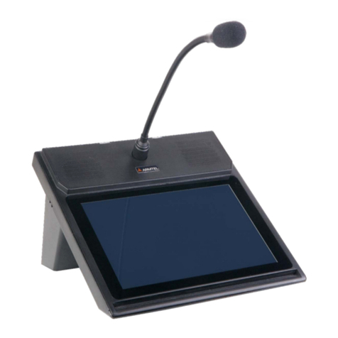
ARMTEL DIS-IP2 User manual

ENG
DIS-IP2
Desktop call
station
RMLT
.465311.001
UM
User Manual
Version 11
26.30.
23
.
00
0
20
2
1

armtel.com
© Armtel info@armtel.com

DIS-IP2 DESKTOP CALL STATION
USER MANUAL
armtel.com page 1/37
info@armtel.com © Armtel
ENG
INTRODUCTION
This User Manual applies to the DIS-IP2 Desktop call station RMLT.465311.001 manu-
factured by Armtel LLC, and is intended to familiarize the User with the device and the pro-
cedure for its operation at the installation site.
DIS-IP2 Desktop call station is a subscriber's equipment of the operational-
technological communication and loud notification system.
Short name of the product - DIS-IP2.
The maintenance personnel shall be required to know the operating procedure of the
DIS-IP2 to the extent provided for by the User Manual.
Duties of the maintenance personnel shall include maintenance of the DIS-IP2 in ac-
cordance with this User Manual.

DIS-IP2 DESKTOP CALL STATION
USER MANUAL
page 2/37 armtel.com
© Armtel info@armtel.com
ENG
SAFETY PROVISIONS
During installation and operation of DIS-IP2, observe the safety measures specified
by local regulations on electrical safety.
In order to ensure fire safety, follow the following rules:
−before connecting the product to the power supply, make sure the power and
communication cables are properly insulated;
−protect power and communication cables from damage.
To avoid electric shock, do not:
−operate the product with damaged power and / or communication cables.
ATTENTION! IT IS FORBIDDEN TO CONNECT THE EXTERNAL 48 VOLT POWER SUPPLY
TO THE 12 VOLT SOCKET, AS THIS WILL LEAD TO THE DIS-IP2 OUT OF SERVICE!
It is strictly forbidden to disassemble the product connected to an Ethernet network
or to an external power adapter.
Do not use the product in rooms with high humidity of more than 80% or conductive
dust.
The safety provisions for specific operations described in this manual are marked
with:

DIS-IP2 DESKTOP CALL STATION
USER MANUAL
armtel.com page 3/37
info@armtel.com © Armtel
ENG
CONTENTS
INTRODUCTION .............................................................................................................................................1
SAFETY PROVISIONS ....................................................................................................................................2
Contents............................................................................................................................................................3
1 DESCRIPTION AND OPERATION ........................................................................................................ 4
1.1 Product description and operation........................................................................................4
1.1.1 Product function................................................................................................................................. 4
1.1.2 Specifications ....................................................................................................................................... 7
1.1.3 Design description............................................................................................................................. 8
1.1.4 Labeling .................................................................................................................................................. 9
1.1.5 Package.................................................................................................................................................10
1.2 Description and operation of product components .....................................................11
1.2.1 General..................................................................................................................................................11
1.2.2 Main board..........................................................................................................................................11
1.2.3 LED pushbuttons ..............................................................................................................................12
1.2.4 Wi-Fi module......................................................................................................................................13
1.2.5 ADSL modem.....................................................................................................................................13
1.2.6 Gooseneck microphone................................................................................................................13
2 FUNCTIONAL OPERATION..................................................................................................................15
2.1 Operational restrictions ...........................................................................................................15
2.2 Preparation for use....................................................................................................................16
2.3 Product installation and connection ...................................................................................16
2.4 Product operation......................................................................................................................17
3 PRODUCT MAINTENANCE..................................................................................................................24
3.1 General...........................................................................................................................................24
3.2 Safety precautions .....................................................................................................................24
3.3 Product maintenance procedure..........................................................................................24
3.4 Checking operability .................................................................................................................25
3.4.1 Checking acoustic path .................................................................................................................25
3.4.2 Checking button operation.........................................................................................................25
4 REPAIR........................................................................................................................................................26
5 STORAGE...................................................................................................................................................27
6 TRANSPORTATION ................................................................................................................................28
7 DISPOSAL ..................................................................................................................................................29
Appendix АExternal appearance of call stations with 16, 24 and 32 keys............................30
Appendix B Product connection...........................................................................................................31
Appendix C Use of DIS expansion unit................................................................................................33
Appendix D Indication types of direct key backlight .....................................................................34

DIS-IP2 DESKTOP CALL STATION
USER MANUAL
page 4/37 armtel.com
© Armtel info@armtel.com
ENG
1DESCRIPTION AND OPERATION
1.1 Product description and operation
1.1.1 Product function
DIS-IP2 Desktop call station is designed for use in distributed and centralized (on the
basis of dedicated SIP-server manufactured by LLC Armtel) PA systems in industrial and
transport enterprises. DIS-IP2 is not for use within public networks and systems.
DIS-IP2 is the subscriber device operating within digital intercom system and pro-
vides service intercom on an installation site, as well as the communication between sub-
scriber devices included into this system structure.
DIS-IP2 can be used in metal, chemical, oil-processing, oil and gas production indus-
tries and other industries with similar application conditions and in transport as well. DIS-
IP2 is installed in control, office and control board rooms.
DIS-IP2 has the versions for 16, 24 and 32 pushbuttons.
The versions of DIS-IP2 are shown in Table 1.
The external appearance of call station versions for 16, 24 and 32 pushbuttons are
given in Appendix А.
Table 1 - Versions of DIS-IP2
Designation
Number
of pushbuttons
Add. module ADSL Weight, maximum, kg
RMLT.465311.001
8
-
0,97
RMLT.465311.001-01
16
-
1,03
RMLT.465311.001-02
24
-
1,09
RMLT.465311.001-03
32
-
1,15
RMLT.465311.001-04
8
ADSL
1,00
RMLT.465311.001-05
16
ADSL
1,06
RMLT.465311.001-06
24
ADSL
1,12
RMLT.465311.001-07
32
ADSL
1,18

DIS-IP2 DESKTOP CALL STATION
USER MANUAL
armtel.com page 5/37
info@armtel.com © Armtel
ENG
Besides, up to four expansion units DIS ARMT.665230.207 (Appendix C) can be con-
nected to DIS-IP2 to increase the pushbuttons number.
DIS-IP2 provides the following functions within digital intercom system:
−simplex subscriber communication via SIP, Armtel-IP protocols;
−duplex subscriber communication via SIP protocol;
−communication between terminal devices via wireless data transmission
channel Wi-Fi or via twisted pair through two Ethernet ports (for all versions),
as well as using ADSL (for versions -04…-07) – see Table 1;
−recording of speech messages on DIS-IP2, using programmed pushbutton
with the local function of fragment recording. The record is performed in
WAV file format, with line coding of 16 bit 16 kHz; the message size depends
on the availability of free space in the device storage;
−replaying of speech messages on terminal devices;
−calls with the account for priorities via SIP, Armtel-IP protocols, organization
of unilateral control mode and Cancel function;
−volume control of built-in loudspeakers and calling signal, using programmed
pushbuttons with local functions Increase volume and Reduce volume;
−control of АСМ-IP2 analogue subsystem module for organization of zone
loud-speaking address system, using Relay function.
The configuration of DIS-IP2 is carried out from the personal computer of IPN net-
work administrator, where the software “Configuration software tool of IPN2 system”
RMLT.00041-01.
Figure 1 shows the typical connection diagram of DIS-IP2.

DIS-IP2 DESKTOP CALL STATION
USER MANUAL
page 6/37 armtel.com
© Armtel info@armtel.com
ENG
Figure 1 – Examples of using DIS-IP2 in distributed loud-speaking intercom and PA systems
For example, organization of communication over the routes:
−simplex: DIS-IP2 – Ethernet interface –Fast Ethernet Switch – Ethernet inter-
face – DW-IP2 loud-speaking call station;
−duplex: DIS-IP2 – Wi-Fi – Wi-Fi hotspot – Ethernet interface – коммутатор
Fast Ethernet Switch – Ethernet interface – SIP-phone No.103 – Ethernet in-
terface – Fast Ethernet Switch – Ethernet interface – Wi-Fi hotspot – DIS-IP2.
Organization of zone public address over the route:
−DIS-IP2 – ADSL interface – DSLAM – Ethernet interface – коммутатор Fast
Ethernet Switch – Ethernet interface – АСМ-IP2 module – external amplifier –
4-relay modules – loudspeakers (up to 8 ps.).

DIS-IP2 DESKTOP CALL STATION
USER MANUAL
armtel.com page 7/37
info@armtel.com © Armtel
ENG
1.1.2 Specifications
Main technical and operational characteristics of DIS-IP2 are given in Table 2.
Table 2 - Main technical and operational characteristics of DIS-IP2
Parameter Value
Power supply through PoE line (IEEE 802.3af/ IEEE 802.3at), V
-48
External DC power supply, V
12 or 48
Maximum consumption current through PoE line, maximum, А
0,3
Maximum consumption current at 48 V, maximum, А
0,3
Maximum consumption current at 12 V, maximum, А
1,2
LF-signal bandwidth (at -3 dB level)*, Hz
From 300 to 6800
Maximum electrical power of built-in two-channel amplifier per each chan-
nel, minimum, W
1,0
Communication interface**
100BaseT Ethernet
Communication protocols via Ethernet interface
SIP, Armtel-IP,
SNMP
Communication interface*
ADSL, ADSL2,
ADSL2+
Communication protocols via ADSL line
IEEE802.3,
IEEE802.3u, ITU
G.992.1…992.5
Communication interface
WI-FI 2.4
Communication protocols via Wi-Fi
IEEE 802.11a/b/g/n
Electrical protection class (under GOST IEC 61140-2012)
III
Protection degree
IP40
Air temperature range, ºC
From - 5 to + 55
Relative air humidity at +25 ˚С, %
Up to 80
The total duration of sound fragments recorded in the device's memory, mini-
mum, minutes
1500
Overall dimensions, maximum, mm (with fully turned up microphone)
285×200×416

DIS-IP2 DESKTOP CALL STATION
USER MANUAL
page 8/37 armtel.com
© Armtel info@armtel.com
ENG
Table 2 - Main technical and operational characteristics of DIS-IP2 (end)
Parameter
Value
* Only for direct calls without using sound files (except for local sound files with a sampling
rate of 32 kHz (located in the local memory of the device) using the SIP protocol and when using
the SIP codec G.722.1С.
When using the Armtel-IP protocol, the bandwidth is from 300 to 6800 Hz.
** Two Ethernet ports: "LINE" - is the main one, the second one is backup, including when
powered by PoE.
1.1.3 Design description
The enclosure and cover of DIS-IP2 are made of ABS gray color plastic RAL7035,
the cover has special form for better view of the pushbuttons. The external appearance
of DIS-IP2 with eight pushbuttons with the overalls and fully turned-up microphone
is shown in Figure 2.
The printed board is installed in the enclosure, containing the electronic components
necessary for DIS-IP2 functioning, as well as the modules:
−Wi-Fi module WM1123WU with antenna MaxLink 2,4/5GHz 5dBi Omni RP-
SMA (for all versions);
−modem ADSL Module IB02 v5.0 (for versions RMLT.465311.001-04…-07).
The enclosure is equipped with the rubber legs protruding from below, to make the
product steadier.
Each DIS-IP2 comprises the embedded software and configuration data, allowing it to
connect with other network subscribers directly, via wireless data transmission channel Wi-Fi or
using ADSL, as well as to control the communication and indication modes.

DIS-IP2 DESKTOP CALL STATION
USER MANUAL
armtel.com page 9/37
info@armtel.com © Armtel
ENG
1 – enclosure; 2 – cover; 3 – built-in-loudspeakers; 4 – LED pushbuttons; 5 – electret microphone;
6 –RJ-45 connectors for cable connection to Ethernet; 7 – RJ-11 connector for ADSL line connection;
8 – Wi-Fi antenna NETIS PA105S; 9 – connector for external power supply 12 V; 10 – connector for
external power supply 48 V; 11 –socket for output of DIS expansion unit in case of its use.
Figure 2 – External appearance and overalls of DIS-IP2
1.1.4 Labeling
On the bottom of the DIS-IP2 enclosure is placed bilingual laser engraved nameplate.
The nameplate contains the following information:
−name, trademark and reference information of the manufacturer;

DIS-IP2 DESKTOP CALL STATION
USER MANUAL
page 10/37 armtel.com
ENG
− product name and description;
− permissible operating temperature range;
− degree of protection provided by enclosures (IP code);
− commercialization mark for products on the market of Customs Union member
states;
− electrical class III mark according to GOST IEC 61140-2012;
− special waste disposal mark;
− product serial number;
− MAC addresses;
− date of manufacture;
The serial number and MAC addresses are unique for each product.
1.1.5 Package
The DIS-IP2 with the assembly kit and documents, which come with the supply pack-
age, is packed in consumer package (cardboard box) according to GOST 23088-80.
A label in Russian language and English language is glued onto the consumer pack-
age, said label containing the following inscriptions and symbols:
− product name and description;
− name, trademark and reference information of the manufacturer;
− handling symbols according to GOST 14192-96 and CU TR 005/2011;
− commercialization mark for products on the market of Customs Union mem-
ber states;
− serial number and date of manufacture.
The package is made according to the drawings of the product manufacturer and en-
ables storage of the DIS-IP2, provided requirements set in Section 5 are met.
For shipment of the DIS-IP2 from the manufacturer, consumer package contents are
placed in the package place, which ensures protection from mechanical damage, direct in-
gress of atmospheric precipitation, dust and solar radiation during transportation.

DIS-IP2 DESKTOP CALL STATION
USER MANUAL
armtel.com page 11/37
info@armtel.com © Armtel
ENG
1.2 Description and operation of product components
1.2.1 General
DIS-IP2 components are described herewith:
−the main board, LED pushbuttons;
−Wi-Fi module;
−ADSL modem;
−gooseneck microphone.
1.2.2 Main board
The main board external appearance is shown in Figure 3. The main board is a printed
circuit board with electronic components, necessary for functioning and connecting
DIS-IP2 in the process of operation.
Figure 3 – DIS-IP2 main board

DIS-IP2 DESKTOP CALL STATION
USER MANUAL
page 12/37 armtel.com
© Armtel info@armtel.com
ENG
The main board includes the following:
−Х8, Х9 – connectors for connection of Ethernet with РоЕ function;
Indicators on the connectors:
1) Green – lights, when physical connection with Ethernet is established, flashes, when
the network interface is active (packet data receipt or transfer);
2) Orange – lights with the device supply from PoE source;
−Х17 – connector for ADSL connection;
−Х13 – not used;
−Х5 – connector for Wi-Fi antenna connection;
−Х26 – connector for connection of external expansion unit DIS
ARMT.665230.207;
−ХР4…ХР7 – connectors for pushbutton connection;
−Х15, Х16 – connectors for built-in loudspeakers connection;
−Х14 – microphone connector;
−Х19 – connector for external 12 V power supply connection;
−Х18 – connector for external 48 V power supply connection;
−U13 – ADSL module (to be installed in versions -04…-07 –Table 1);
−S4 – return to default settings button.
1.2.3 LED pushbuttons
The LED pushbuttons are located by eight pieces in the row (pushbutton module).
Depending on the version, it can be from 8 to 32 pushbuttons (Table 1). The communica-
tion function can be assigned to any pushbutton.
Each pushbutton has backlight with two LEDs placed under it. The LED indication
mode for each pushbutton, the direct call pushbuttons included, are assigned by the soft-
ware.
The main variants of pushbutton indication:
−when pressing the pushbutton, the backlight is activated for the period of
pushbutton hold;
−the first pressing the pushbutton activates the backlight, the repeated one
deactivates it;

DIS-IP2 DESKTOP CALL STATION
USER MANUAL
armtel.com page 13/37
info@armtel.com © Armtel
ENG
−the backlight LED flashes upon input call.
The LEDs group for a pushbutton activates in series, the protection against a break or
disruption of one of the LEDs. For the surface mount LEDs, maximum consumption current
per single pushbutton of two parallel-connected LEDs is less than 3 mА.
DIS-IP2 pushbuttons have higher mechanical strength and wear-resistance. One can
place necessary caption under the transparent cap of each pushbutton. To that end, it is
necessary with deactivated DIS-IP2 to press two pushbuttons placed to the right and to the
left from that one, where the caption is to be inserted, and, holding them pressed, to press
lightly on the cap side walls, disengaging it from the latch. The cap can be pushed up and
the plate with caption is to be inserted; after that, the cap can be latched back.
1.2.4 Wi-Fi module
In order to provide communication between the devices via wireless data transmis-
sion channel Wi-Fi, DIS-IP2 is equipped with Wi-Fi module WM1123WU manufactured by
Wieson Technologies and antenna NETIS PA105S. This module is mounted on DIS-IP2
main board for all the product versions. The omnidirectional antenna according to the
manufacturer information has the following parameters:
−frequency bandwidth from 2,4 GHz to 2,4835 GHz;
−50 Ohm impedance;
−5 dB effective gain;
−RP-SMA interface.
1.2.5 ADSL modem
In order to provide data transfer via DSL channel, DIS-IP2 is equipped with ADSL
Module IB02 v5.0 modem (for versions RMLT.465311.001-04…-07). This module is mount-
ed on the main board in U13 socket according to Figure 4.
IB02 module can automatically identify and automatically switch between ADSL,
ADSL2 and ADSL+ standards, with the maximum rate of output traffic 1 Mbit/sec, while
the maximum input rate is 24 Mbit/sec (ADSL2/2+). The maximum distance of data transfer
can reach 5,5 km, with the observation of conditions stated in standards ITU
G.992.1…992.5. The DC supply voltage of IB02 module is 5 V, the maximum consumption
power is 2,5W.
1.2.6 Gooseneck microphone
DIS-IP2 design uses the stationary highly sensitive electret microphone on flexible
rack G14-1 of gooseneck type, whose external appearance is shown in Figure 4. The micro-
phone design comprises firm stationary and movable flexible parts for easy adjustment of
the microphone inclination in the process of operation. For additional indication the upper

DIS-IP2 DESKTOP CALL STATION
USER MANUAL
page 14/37 armtel.com
© Armtel info@armtel.com
ENG
microphone part is equipped with red LED ring. The microphone is supplied with a wind-
screen, presented in Figure 5, which allows making sound more clear (to exclude the oc-
currence of unwanted whistle and other similar disturbances).
The main microphone parameters are given in Table 3.
Table 3 - The main microphone parameters
Parameter Value
Frequency range, Hz
100 - 10000
Sensitivity, dB
- (38 ± 3)
Rated supply voltage, V
5
Consumption current, mА
< 0,5
13
53
28
8
335 3
+
Figure 4 – External appearance and overalls of G14-1 microphone
Figure 5 – External appearance of the microphone wind screen
The LED backlight on the microphone constantly lights with the call station initializa-
tion, as well as during the pushbutton press to transfer voice information from both the
microphone and with a sound fragment translation, duplex connection including. With the
input simplex call and with the manual duplex control or unilateral telephoning control, the
backlight flashes with the rough period of 0,6 sec during the input call translation to the
built-in loudspeakers.

DIS-IP2 DESKTOP CALL STATION
USER MANUAL
armtel.com page 15/37
info@armtel.com © Armtel
ENG
2FUNCTIONAL OPERATION
The product is designed for continuous round-the-clock work. After entering in the
operation of the product does not require operator intervention, except in the following
cases:
−maintenance;
−product configuration changes.
Service personnel are obliged to strictly follow this document, observing the safety
rules.
The product, together with the operational documentation, is delivered to the cus-
tomer in packet.
2.1 Operational restrictions
2.1.1 DIS-IP2 Desktop call station shall be used under exposure factors and am-
bient parameters which do not exceed permissible values given in Table 2. When us-
ing the product, safety precautions laid out in “Occupational safety rules when oper-
ating electrical installations” should be complied with when working with electrical
receivers with voltage of up to 1000 V.
2.1.2 In case of РоЕ plus power loss, it is necessary to supply 12 V or 48 V power to
DIS-IP2 from the external adapter through the sockets on the side surface in accordance
with Figure 2б. The DC 12 V or 48 V adapter must have the output power of minimum 20
W and is equipped with the connector of P1J type, with the socket diameter of 2,1 mm,
with the plus potential to be output to this socket according to Figure B.3 of B Appendix.
ATTENTION! DO NOT CONNECT 48 V EXTERNAL POWER TO 12 V SOCKET,
BECAUSE IT WIIL RESULT IN THE CALL STATION FAILURE!
2.1.3 When using up to four DIS ARMT.665230.207 expansion units in combination
with DIS-IP2, it is not recommended to apply PoE power of IEEE 802.3af standard, as cor-
rect operation of the devices is not guaranteed in this case. It is necessary to use alterna-
tive supply methods (from the external power supply source through 12 V/48 V adapter or
PoE plus IEEE 802.3at standard).
2.1.4 The requirements for operating conditions and the choice of the place of
installation given in this document take into account the most typical factors that af-
fect the operation of DIS-IP2.
Factors that cannot be predicted, estimated or verified, and which the manufacturer
was unable to factor in during development may exist or arise during operation at the op-
erating facility.

DIS-IP2 DESKTOP CALL STATION
USER MANUAL
page 16/37 armtel.com
© Armtel info@armtel.com
ENG
In the event of such factors, find another operating site where said factors do not ex-
ist or do not affect operation of the product.
2.2 Preparation for use
DIS-IP2 preparation for use is carried out by representatives of the manufacturer, or
by personnel trained (instructed) in the operation of Armtel LLC products. The main prepa-
ration of the product for use is carried out during installation and connection. Preparing
DIS-IP2 for work includes a number of activities:
−removing DIS-IP2 from the shipping container;
−removing DIS-IP2 from the customer package;
−check the scope of supply of DIS-IP2 according to product passport;
−inspect DIS-IP2 enclosure visually, no mechanical damages (cracks, dents,
etc.). In the process of external inspection, pay attention to the integrity of
the products, the state of the buttons (everything should be easy to press
and easily return to its original state) and the microphone;
−install DIS-IP2 at the operation site.
2.3 Product installation and connection
2.3.1 DIS-IP2 has a desktop installation. DIS-IP2 is connected to the network by
100BaseT Ethernet interface. The in-situ connection is performed by the multicore commu-
nication cable of UTP type, tightened by RJ-45 plugs and connected to one of RJ-45 sock-
ets in accordance with Figure 2с. From the opposite side the cable is connected to the
network device with PoE supply function.
Connect to the pluggable terminal block on DIS-IP2 back panel the Wi-Fi antenna
from the expansion unit scope of supply in accordance with Figure 2с. For the product ver-
sions -04…-07 connect to RJ-11 pluggable terminal block the ADSL line in accordance with
Figure 2с.
When using DIS expansion unit, connect the flexible flat cable included into the ex-
pansion unit scope of supply to Х26 connector in accordance with Figure 3 and output it
through the socket between the cover and enclosure of DIS-IP2 in accordance with Figure
2бb.
In the passport, make notes about the place and time of installation of DIS-IP2.
2.3.2 Dismantling DIS-IP2:
−disconnect the external power supply and (if used);
−disconnect the power and/or communication cable from the RJ-45 socket;

DIS-IP2 DESKTOP CALL STATION
USER MANUAL
armtel.com page 17/37
info@armtel.com © Armtel
ENG
−disconnect ADSL line (for version identification -04…-07);
−pack DIS-IP2 and components into the customer manufacturer’ package.
2.4 Product operation
2.4.1 DIS-IP2 can be used as intended in various modes, e.g. in simplex mode, in
communication mode with telephone system based on SIP, when establishing communica-
tion session, using ADSL or Wi-Fi. The mode selection and setting is performed, when con-
figuring DIS-IP2. To ensure the best communication quality during negotiations, it is rec-
ommended to maintain a distance of approximately 20 – 30 centimeters, but not less than
12 cm.
2.4.2 Upon delivery, DIS-IP2 has a set of characteristics assigned by the manufacturer
by default. The following network settings are set:
−IP-address – 192.168.100.10;
−subnet mask – 255.255.255.0;
−default gateway – not set;
−web-interface password – not set;
−network interface – eth0;
−subscriber number – 100;
−SIP server – not set.
The default characteristics are stored in the file «default.par».
Before use, the DIS-IP2 must be configured according to the functions it is to per-
form. The configuration is carried out from the administrator's PC, on which the software
"Configuration Tool of IPN2 system" RMLT.00041-01 34 01 should be installed.
When configuring the DIS-IP2, the network settings are specified and the button
functions are programmed.
As the presence of devices with similar IP-addresses in one network is not admitted, it
is necessary to perform the network parameters setting for each DIS-IP2 prior for connect-
ing to the common network. In the DIS-IP2 passport, write down the set IP address.
Additionally, the pushbutton function programming is carried out, when configuring
DIS-IP2. The functions accessed for configuration to the direct call pushbutton are grouped
in the program by functionality. Certain individual function may be assigned to each DIS-
IP2 pushbutton depending on the type of protocol used ("Armtel-IP" or SIP), for example:
Conference, Circular, Selector etc.

DIS-IP2 DESKTOP CALL STATION
USER MANUAL
page 18/37 armtel.com
© Armtel info@armtel.com
ENG
In the process of call, transfer or receipt of messages the indicators on the corre-
sponding pushbuttons, depending on the functions setting can signal about the communi-
cation organization results by flashing with different degree of intensity.
The types of pushbutton signaling DIS-IP2 within the SIP and «Armtel-IP» protocols
are given in Appendix D.
Also, using the software "Configuration Tool of IPN2 system" RMLT.00041-01 34 01,
the file with the default settings can be changed. To do this, select the edited device and
click the "Save file config" button. This will copy the current device configuration to the de-
fault settings file on the device. The "default.par" file is available for downloading and up-
loading via the TFTP protocol.
2.4.3 To return to the default settings, remove the cover (2, Figure 2) from the case (1,
Figure 2), press and hold the "S4" button (Figure 4) on the DIS-IP2 board for at least 5 sec-
onds. After releasing the button, the configuration file is read with the default settings "de-
fault.par", followed by saving the settings to the main configuration file and rebooting the
device. After the end of the reboot process, the device starts working with the default set-
tings. Then replace the cover.
N o t e s
1Return to default settings after power on and boot DIS-IP2.
2.4.4 Troubleshooting list
If there is a malfunction, poor audibility, etc. – call the person responsible for the op-
eration of DIS-IP2. The troubleshooting are given in Table 4.
Table 4 – List of possible malfunctions and actions for their elimination
Problem Possible Cause Action
Subscriber cannot
make and receive
calls
No supply on the device
Check the reliability of supply connec-
tion, be assured that supply voltage is
delivered to the subscriber device
Wrong configuration of
DIS-IP
Upload the correct configuration param-
eters
Orange LED on
the network con-
nector (pos. 6 Fig-
ure 2) is off
Lack of supply by PoE line
Check the connection reliability, be as-
sured that supply is delivered through
PoE line
Overload on PoE
supply
line
May be accompanied by short time or-
ange flashings on the connector.
Check
the value of load current on РоЕ line
This manual suits for next models
1
Table of contents
Other ARMTEL Intercom System manuals
Popular Intercom System manuals by other brands
Carus
Carus CAI 1010 Assembly instruction
Planet Networking & Communication
Planet Networking & Communication HDP-5260PT user manual
Digital Acoustics
Digital Acoustics IP7-FD Getting started guide
Bticino
Bticino 313211 instruction sheet
Bell System
Bell System 500A Wiring diagram

Futura Digital
Futura Digital VDT591 user manual
