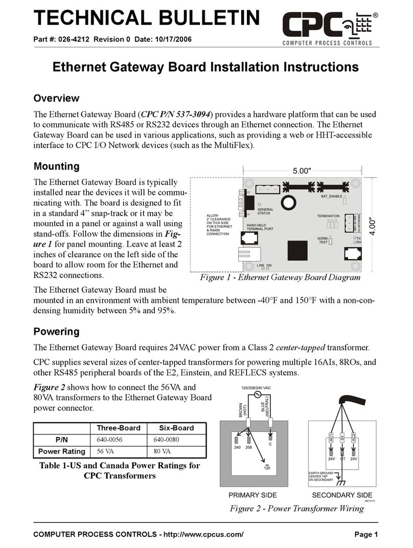
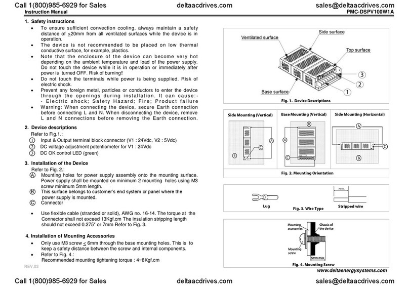
CPC 537-3010 User manual

16.AI DPAI\SIOI{ BOARI)
FOR
Part Nos.
s37-3010
810-1020
810-2020
DOCUMENT No. 025-3010
December, 1988
Data, drawings and other material contained
herein are proprietary to Computer Process
Controls, lnc. and may not be reproduced
without the prior approval of Computer Process
Controls.
Computer Process Controls, lnc.
1275 Kennestone Circle, Suite 100
Marietta, GA 30066 (404) 425-2724 C?C

CoUPUTER PROCESS CONTROLS, INC.
16AI EXPANSION BOARD
The CPC l-6AI Expansion Board is an optional add-on board available
for the CPC L6O2 Monitor and Control Unit (l{CU). The 16AI Expansion
Board provides the L6O2 with an additional l-6 inputs which may
beprogrammed as analog or dry contact digital. Two 16AI boards may
be added to a L6o2 I'{cU, bringing the total number of inputs up to
64.
The L6AI is connected to the L6o2 by way of the rrExpansion
Communication Bustt, which means the l-6AI boards can be mounted
where the devices being monitored are located. This |tremote
locationrt feature will decrease the installation time and cost
since only a shielded 2-conductor communication cable is requi-red
to connect the 16AI to a L6O2 UCU.
SPECTFICATIONS
Microprocessor
Communications
Field Inputs
Power Reguirement
Features
Failure Protection
8751- Microcontroller
RS-485 Interface operationg
at L200, 24OOt 4800, or
9600 baud.
l- to L6 analog (-1 to
+7VDC) OR l- to L6 DRY
CONTACT diqital inputs
1OVAC, 7.5 volt-amps
(0.75A) from a 20 volt
center-tap transformer
Switch selectable network
ID
Switch selectable baud rate
LED for power/communication
4-5VDC conectors and 4-
I-2VDC connectors (L00 mA
maximum load for any one
connector with 320 mA
maximum combined load)
Automatic reinsertion into
network
10rr x 4rr x 2tt (LxWxH)
Dimensions

Mounting Dimensions 6 - 6/32 screws (3/side)
(see FIG. 3 dinensions) -'--'/
approx. 1 Ib.
1:ON
0=OFF
Weight
HARDWARE SETUP
1. 16AI Board Hardware Setup (See FIc. 3)
a. 5L-S2 Temperature Switches determine whether an input is
to be used to monitor temperature.
If the input is to be used to read temperature or
as a DRY CONTACT digital, the corresponding switch
on SL or 52 should be ON. For any other type input,
linear, pressure, etc., the switch should be OFF.
b. 53 Network Switches set the Expansion Bus Device ID and
baud rate.
Switches 1-5 define the board device number (1"-L6).
Each 16AI on the Expansion Communication Bus must
have a different device number, but these device
numbers are group independent so a L6AI and a L6O2
MCU nay both be assigned device number L. Set the
device number using the table below.
POSITION
L2345
0 00000 l-=ON
L 1-0000 O:OFF
2 01000
Switches 6-7 set the RS-485 baud rate. Set the baud
using the table below.
BAUD POSITION
67
ID
12 00
2400
*4800
9600
00
L0
01
11_
2

c. Jumpers JUlrJU2rJU3 set terminating resistance for the
RS-485 communication bus.
DEVICES AT THE END OF THE EXPANSION COMMUNICATION
BUS REQUTRE TERMINATING RESISTORS FOR PROPER
OPERATTON OF THE RS.485 LINE.
These jumpers are located on the l-5AI board right
next to the RS-485 communication terminal block.
The jumper positions depend on how the Expansion
Communication Bus is wired. Use FIG.1, FfG. 2 and
the configurations bel-ow to constuct a 2-conductor
shielded wire cable. The cable should be 20 gauge
Belden #91-54 or eguivilent.
The 1-602 is used below as an example. Other devices
communicating on the Expansion Bus will follow the same
general rule.
rt 15AI--- -L6O2-- -- 1 6AI *
* 15AI----15 02 ----L6AI----16AI *
:tL6O2----l-5AI*
:t 1 6 0 2 ---- 15AI---- 16AI it
rc LG O2---- 1 6AI---- 1 6AI---- L 6AI !t
* marked devices reguire terminating
resistors
L. 16AI Board set up as an END device (* marked)
requires jumpers, JUI-, JVz, JU3 to all be in their
positions CLOSEST to the RS-485 communication
terminal block.
2. 16AI Board set up as a MIDDLE device (unnarked)
reguires jumpers, JUL t JV2, JU3 to all be in their
positions AWAY from the RS-485 communication
terminal bIock.
3. L6O2 set up as a MIDDLE or END device
(marked/unmarked) reguires no changes since
terminating resistors are not needed.
3

d. 16Af Power Requirements.
Each 16AI reqires 1OVAC and draws a maximum of
0.75A. CPC, Inc. recommends a 20VAC, 2.AA, center
tap transformer (T1- below) to power 2 16AIrs. A 2-
conductor shielded wire (20 gauge Belden #9L54 or
L6 gauge Be1den #87L9 for long runs) should be used
to connect the transformer, T1, to the L5AI Power
Connector.
t-t_______
tzovAc I *r l-------
!_l-------
e. Connecting the Inputs.
16AI Power Connectors
l_6Ar #r L6A1 #Z
Acr. ( 1-) Acl ( r_)
ov (2) 0v (2)
Ac2 (3) Ac2 (3)
ON
OFF
The input conections are numbered l- to 32. Grouped
in pairs, the odd numbered inputs are conmon and
even numbered inputs are signal. The terminal block
on the end of the board with 4-5VDC and 4-I-2VDC
conections can be used to power sensing devices
such as pressure transducers. The total load
available from this terminal block is 320 milliamps.
The maximum load from any one connection on the
terminal block is .L00 mA. For example, 5 pressure
transducers requiring 5 volt references could be
connected to a single 5 volt connector on the
terminal block as long as each transducerrs load
does not exceed 20 mA.
2. 1,602 Expansion Bus Device Hardware Setup.
Any device communicatiing on the Expansion Bus with the
L6AI board(s) will have to have a matching baud rate. The
L6O2 MCUts baud is set using switches 3 and 4 on the
Digital I\O Board. See the rt1602 llonitor and Control
Systemrr Manual, FfG.2-21 .
BAUD POSITION
34
12 00
2400
*4800
9500
1-
I-
Q=
00
L0
0L
1L
4

SOT'TWARE SErUP
l-. Programming the L6O2 Expansion Bus Network Setpoints.
a. Network Device Numbers.
Each L6AI on the Expansion Bus must have a
different device number, but since the device
numbers are group independent, the L6O2 MCU and the
L6AIrs can both start r*ith Device number l_. From
the L6O2 trMain Menutr, select 10, the ttsystem Inforl
Menu. Select ffDevicetr to define the device numbers.
Enter the Expansion Device Number for the 1602, and
likewise for the L6AI Input Boards. Make sure that
the L6Af device number corresponds to the l_6AI
switches 1-5 set on SL (see l-6AI Board Hardware
Setup).If the board does not exist, enter a 0 for
rrundef inedtr.
b. Network ON/OFF Feature.
Select L3 from the rrMain Menutr to display the
ItNetwork Menurr. The rrResetrr option allows the
Expansion Bus Network communication to be turned
OFF or reset (turns Network ON). This completes the
Network progranming.
2. Programming the 1-602 Input (32-64) Setpoints
The expansion of the inputs from 32 up to 64 does not
change the rrlnput Menurr except to reflect the increased
number of inputs. rf the 16Ar should fair due to a hardware
or communication problem, the L6O2 has several built in
safeguards. rf failure shourd occur, the t-602rs L6Ar Anarog
inputs wilI automatically go into the OpEN state. Outputs
controlled by these sensors can be prograrnmed to opEN or
CLOSE if the sensor fails (ca11ed rrsensor Fail Overrideil).
The l-602rs 16Ar digital inputs can be progranmed to opEN or
CLOSE (caIIed rrDefault Statef) should the 16AI fai1.
5

MONITORING
1. L6O2 Network Monitoring
To see if the Network is operating after rProgramming the
Network Setpoints" and frProgramming the 1-602 Inputslr,
select rrlnputsrr from the 1602ts ttMain Menurf . Now select
rrPresent Analogrr or rrPresent Digitaltt and notice the
headings. The headings displays an ONLINE or OFFLINE status
for each l-6AI board. ff a 16AI board is OFFLINE, check the
1602 | s rrUnacknowledged Alarns Logtt and see rrNetwork Errors[
in this rnanual for the problem cause/solution.
2. Network Errors.
Although every precaution has been taken to make the
Expansion Bus Network rrmaintenance freett, occasionally the
need for operat'or -intervention may be needed. Network
errors appear in the ttlogging Menurf under Unacknowledged or
Acknowledged Alarms.
Message Notice/AIarm
No Expansion Devices
Node ONLINE 8RO ID : l-
Token Pass Missed 8RO ID : l-
No Response - Node OrFLINE 8RO ID = L
Bad Msg. - Node OFFLINE 8RO ID = l-
Bad CKSum - Node OFFLINE 8RO fD : l-
AIarm
Notice
Notice
Alarm
Alarm
Alarm
The rrNo Expansion Devicesrt Alarm means the Network is down
due to either a hardware or progranming problem. This Alarm
should be followed by one or more trNode ONLINE...rr
Notice(s) within 7-8 minutes. If no rrNode ONLINE...rt Notice
occurs, Check the RS-485 communication line and step back
through rrProgramming the L6O2 Network Setpointstf .
The last 3 alarms the result in rt...Node OFFLINE...rr and
should also be followed by a rrNode ONLINE...rr notice. If no
ItNode ONLINE...rr Notice occurs, check the hardware and
programming as described above.
The trToken Pass Missed...frerror is self correcting and
reguires no action.
Most of the above errors tend to be ttself correctingtt. If
an expansion board is disconnected from the Expansion
Communication Bus powered downr or goes OFFLINE for any
reason, the 1602 will check on the board once a minute
until it responds or is removed from the device definitions
(rrSystem f nforr Menu) .
6

flll
lllt
Itt: ll
---qtr--
gqf-61
u atv)t
U'l nl
JqLVI
i ds,l
F
@
ltil
lL Ell
-_rJr--
* {@l
i4sl
ildNl
E
(9
C-
C-7\
\-----l Y
L
\_J J
- -i.i (J
Ui ". o
\----r _q ca
tr-
$? z0z e0? '0e soz 90? /0? 8oa
@@@ea@N(D
S
e
N
(D
N
S
@
c
c
@
S
(\,
CI
N
S
N
@@aea@NCI
\--
0r
(_
l
9)
Lr-
EE
EE E IEE !-sr
AZ r^ ^ -:t S6-oTot = f t
*=;YffiffiFP=

a
M
{ a-r
EN
ca v)
Z
trdf
af
Z-U
{{
o_
><c
u=
C
_C
{v)
I ._,,
\c
i--
@
o
\o
:_
tt
.+
\o
rU
\o
I
Ol
ul
+
f
&
c
l-
o
({-
t4
o-
J
L
l
o-
o
I
Vr
+,
f
a
c
L
o
q-
t
o
fI
=
f,
o-
o o, ^t-L
sI !.7Jf, i# 5
; g;#EE; h=a't
E -Pg 9t$ $ r-H o
Sslit;lti,g:
t,3o*.E,i+5
vr++ f oJ l1t or f V
frEoLtuc(,=I,-
EOo-co-o>0rlrl
JCENUylO.+LUIE
V)
ru
.!|
Gl
Or
l"
@
ci
z.
H
ti
J
trl
u
t--
z.
tl
o r-t
V) {T
l,{ \I)
Es_l
M
o-
M,
td
F
=
o_
=
tl
(J
Etx
hr-rf I Er
lsrrr I .}
l"trE I I
Fr--LJ | :z
IDr-E I t
kurn I q)
l-rrr I >
lEz.=-) q
@
z
=
sffid 5H?
,L=#zF*
gfffi]-ol =3t
4 doa,
ffiq su=
z.
E
F
e8E
a,/t z. I I
i? lo o ol
a-=raE:*#
xEl=
rr.roFe fr, *
*bi
o.r-,
il---l
^
\/Xffi
/\
II
\t
\--./
il:il
---_qr-
o, Q[-61
3 allo I
El)l
o- Elloj
E
@F
3,5
LO
\
$
r)
N
+
CI
0,
L
l
?
LL
CU
d
o
c?
GI
--ru(\l
(\l
[]']']',lTl*|
ru
(7)
(f)

SECEN! OPTIONAL) 16-AI BOARD
FIRST 16-AI BOARD
[o^o3'ryryo
LZ E#rrffir TTIf,
V ffi I
| " Notd .t*d rput' o d ffiEEEEEE I I
I r .rtr bdlo ed to I
I _ _ E to. t np.rfiE Ftlt-r{r fa ttlPqtt l-€ I
I I I ffihv.fth I
I 1..-.5 I I @spdoF4Ll+ |
I I I I I rrtdrh.l,rfil(+) I
I I I I I po*u* ltortolrF I
lllllffiffi@_ t_
I I I I I Prdi+.€rLputrH6
I t__i L___l
cuMpurER pRocEss CIINTRIILS, INC. t--------------l r-I
15Ar @ l,,l,l,,l.l.l-l.l..l l-l-1",1*l*l*1,,1*l @
@
0
Note' 140-0020 ls used ln the
l-Boord unltt and the 140-0044
Is used ln the a-Eoord unlt, rl
c
ft
o€
co
go
+
€
€
o
o
EqoS'i l'l'l"l"l"l"l"l"l @
tlot' Uil5.d }prtj sd
tputi b.r€ Ecd ta
ETTT1rTT]
FffiEEEEEE I
Putti+r fr InFJb 1-S
ffi
FmmEffiEl
fr!-r+, fe IryB H6
^dfto. iip.6h
5bjd hovc 1*$
cfispdrdto p.lt-r+
Jrtchh1t l}1 (+)
portba! ltott o l**r
tfr of ffi
rqt l,r gll{
rftdr to b. h lrf,
OFF (dord porth
@ m coMPUrER t*1?"irto"t*DLs' INC' o
Red/18 I I ll lRed/l8

This manual suits for next models
2
Other CPC Computer Hardware manuals
Popular Computer Hardware manuals by other brands

A4Tech
A4Tech RG-20KM user guide
Cana Kit
Cana Kit RASPBERRY PI quick start guide

digi-tech
digi-tech BP80 owner's manual
Contec
Contec CONPROSYS Introduction Guide
j5 create
j5 create ULTRADRIVE KIT JCD387 Quick installation guide

ARTESYN EMBEDDED TECHNOLOGIES
ARTESYN EMBEDDED TECHNOLOGIES SharpStreamer Pro PCIE-7210 Installation and use
