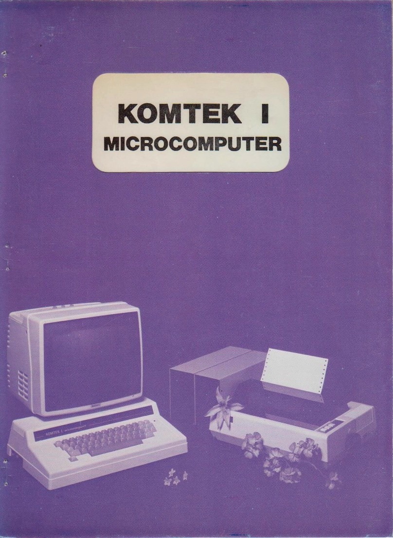
Komtek 1 User manual


INDEX
Page
Introduction 1
The Komtek Computer System 2
Connecting the Computer 4
Starting the Computer 6
Getting to Know Your Keyboard 7
Using the Cassette: Recording Programmes 8
Loading Programmes 9
Listing and Executing Programmes from Cassette Tape 10
Memory Size and Protection 11
Setting the Time 12
Control Functions (Introduction) 13
Using The Color Interface 14
Starting Up a Color Computer 16
APPENDIX
Port Assignment of Komtek I 17
The Configuration of Komtek 1 19

4) The Normal System
In this system you will find that the peripherals can be used on other computers.
a) The Monitor instead of the home TV you replace it with a monitor, if you have a
colour interface and wish to have colour, buy a colour monitor.
When you are working long hours with the computer the steadiness
and clarity of a monitor will reduce your eye fatigue.
b) The Disk Drive - in order to use a disk drive you need a disk diive interface and to
further increase the size of the RAM (Random access memory).
Komtek 1 can be fitted with an extra 16K RAM card on the main
board. This, together with the 3?K on the main circuit board
produces a total of 48K RAM. To justify the use of a disk drive
economically you need 48K. With a full 16K ROM you have a
total memory of 64K. Due to the way the memory is mapped it
would not be worthwhile to exceed 48K RAM unless you are very
knowledgable in computer hardware and software, then you can
disable the existing ROM & put extra memory on another “ page"’
a new big capacity memory. The use of a Disk Drives enables you
to open up a whole new world of disk operating systems and
unlimited disk memory; most important of all fast access speed.
Invaluable for small business use.
c) The Printer - it is desirable to print your program and the results obtained: the way
to do it is with a printer. You may use a dot matrix printer or a daisy
wheel printer. The dot matrix printer produces letters that looks like
those in a cable or telex and is built up of dots. 1'he daisy wheel
printer produces letters that look like those typed on a typewriter
and you can change the fonts too. However this is an expensive
machine!
3

CONNECTING l HE COMPUTER
The following diagrainme shows the connection points of Komtek 1 and is self explanatory.
4

-However certain points worth noting are'
a) The outlet for TV and monitor are not interchangeable: a TV will not work on a monitor
outlet and vice versa.
b) The same goes for the disk drive and printer outlet.
c) When connecting the cassette recorder the white plug should be connected to the MIC input
(microphone input) of the recorder and the black plug should be connected to the EAR
output (earphone output). Ehe thinner blue plug is to be connected to REMOTF.
d) The six control function channels in the rear of the computer has electrical output i.e. live
when the channel is on. It has an output of 4 volts open circuit and I5MA short circuit. The
control function should operated in conjunction with a Komtek control box. In the control
box the computer current is isolated from the high ampere house supply current by an
optical coupler.
Important: any direct application 01 leakage of house current to the control outlet of the
computer will burn out the computer.
e) The 4 sensing functions on the left side of the computer operates on open & close circuit basis.
When it is open circuit externally it is logic high across the shunt resistor inside the computer
and when it is closed circuit externally it is logic low (if you do not understand the above it
does not matter: all you need to know is how to operate the sensing function).
f) All control function channels and sensing function channels have a common ground.
Note: If you do not understand paragraph e) and f) it does not matter, all you need to learn
is how to programme the control and sensing functions and connect them.
g) There are 2 kind of fuses on the Komtek 1. The a.c. power fuse which is at the rear of the
computer, and the inboard fuse on the circuit board for the d.c. current to the.integrated
circuits. If for any reason the red light on the keyboard does not light up and the computer is
not operating you may change the fuse yourself. However we do not recommend changing the
fuse on the circuit board. This is because when this fuse is blown something is wrong with the
circuit. Each time the fuse is blown more of the delicate integrated circuits may be damaged.
The circuit must be checked and repaired before any new fuses are put in. An unserviced
circuit with continual fuse changes will only cause more integrated circuits to burn out!
Note: On the left side of the compute are 3 OUT-IN switch. The first switch nearest to the
sensing function is the RESET SWITCH. When it is pressed in it the computer resets.
When it is released it springs out again. The second switch has 2 functions: When it
is in the OUT position the real time clock is on and running and when it is in the IN
position the real time clock is OFF. When the computer is first turned on it can only
be reset with the switch in the IN position.
When the second switch is lock in the IN position it connects one of the jumper that
is connected to the auto-colour chanegovei resulting in a partial change. The third
switch is a auto-color change switch which connects two jumpers.
Komtek also produces foreign language computers. In KOMTEK DUAL LANGUAGE
computer e.g. English/Indonesian computer, the language changeover is effected by
using the third OUT-IN switch (in which case there is no screen conversion) OR
flipping the power switch from top position to lower position (the middle position
being OFF position), the changeover mode being specified by the distributor of the
respective country.
5

The computer is ready to run the moment you unpack it from the box. Please follow the
following procedure.
1) Turn off the computer before putting the plug into the power socket. This is done by flipping
the toggle switch to up position at the back o f the computer.
9) Check the voltage labelled on the computer to make sure that it is either 220V or 110V. If it
differs you will have to use the correct step up or step down transformer for the moment.
3) Put the power plug into the electrical socket and flip the on off toggle switch down. The red
light on the top right hand corner of the keyboard should light up.
4) At this time there are letters and symbols filling the whole screen like a mosaic. Press RESET
switch or Key, wait for a few seconds for it to reset & the screen will clear showing the
following:
KOMTEK COMPUTER SYSTEM
memory size?
5) You can ignore the phase “memory size?” Proceed to press RETURN and the screen will
show:
READY
> I
6) The computer is now ready to operate on Basic II Level Basic.
7) In the case of Komtek color computer proceed as follow:
a) Turn on power, wait for it to reset.
b) Press RETURN key and then CLEAR (CLR) key
c) For Black & White: POK03579, 2
For Auto color: POKE 13579, 17
For Programmable color: POKE 13579, 4
d) In each of the above case, please do not forget to press RETURN key after poking.
8) Before running the computer adjust the brightness and contrast of your TV or monitor. Do
not make your screen too bright. Bright letters and a bright screen have a hypnotizing effect. It
will make you feel tired and dizzy. Use of the screen for computer purposes differs from the
moving screen of a TV. Sometimes the illuminated letters will stay on the screen for a long
time if you are thinking and checking through the programme. Consequently it is easy to
partialy burn out your TV screen lesulting in poor future display. It is wiser to use a less bright
display. Therefore turn your brightness to a comfortable level and no more.
9) Resetting computer fitted with DISK Interface:
a) Press BREAK key and hold it down.
b) While holding down the BREAK key, press RESET switch or Key down for 2 seconds.
c) Finally release the BREAK key and the procedure is complete.
Note: Sometimes when the computer is first turned on the letters on the screen jumps. In this
case just switch off the computer for 3 seconds and turn on again. This is because the
computer is a delicate machine and is greatly affected by unsteady currents (called
“dirty-current” ). This is caused by faulty fluorescent light, Electric Motors which run
on carbon bushes and the switching on of heavy currents. Since Komtek I is running at
2 MHz it is running near the speed limit o f the chips, it is therefore more sensitive to
current disturbances, adding radio interference suppressor to the external circuit will
overcome this should you suffer from this problem.
STARTING THE COMPUTER
6

The keyboard on your Komtek 1 looks very much like that of a typewriter. We make it that
way so that you will feel at home with it. The main difference is the way the shift key functions.
Without pressing SHIFT key on either side alphabet prints with capital letters. This is because the
computer runs on Basic Language or machine codes & that the programme is a combination of
capital letters and numbers. It would be a nuisance to release the shift lock in order to get the
numbers. Hence the reversal. Here are the general use of the keys:
I ) The RESET key whether on the side of the computer or on the keyboard is for resetting the
computer. It is as if we are saying, "start all over again from the beginning" what it does is to
wipe out all the programmes and data in the memory. When the computer runs wild because
of certain programme which is poorly designed the way to stop it is to reset the computer.
■>) The RETURN key is just like the New Line key on the typewriter. However it also serves as a
kind of command key to tell the computer to start working when you have typed RUN on the
keyboard.
3) The BRHAK key is for you to digress from your present programme into something else. It is a
procedure insertion key. e.g. when you load a programme, for example, a control function
programme & find that you have forgotten to set the time, you press the BRHAK key & insert
the time. After this you go back into the original programme by typing CONI and press
RETURN key. The result of this is that you may not see part of the previous programme, but
you have not lost anything because it is still in the memory. Why? In the process of pressing
BREAK key and inserting your other procedure by typing you have roll or scroll up the letter
on the screen & whatever is scrolled up is not recallable unless there are programmes to do it.
as in word processing.
You can also come back into the programme after BREAK by typing RUN press RETURN
key Lo & behold - you see the complete listing again but you have lost the data you put in!
4) The BACK SPACE key controls the cursor which is a solid rectangular mark to tell you where
you are in typing the next letter. If you have made a mistake in typing press BACK SPACE
key and re-type again. In some version of Komtek I it is replaced by a left hand arrow.
6) The RUB OUT key is not what it implies: we have put it on instead of a right hand side arrow
because there is a provision for future RUB OUT. For the present it is to move the cursor
spaces to the right, in some version of Komtek I it is replaced by a right hand arrow.
7) For one space to the right - press the long space bar.
8) The BACK SPACE & RUB OUT key form a pair of keys which you will be using very often
in playing games. You use it to move your subject or target to the right or to the left.
9) The same goes with the UP & DOWN arrow on the top left hand corner of the keyboard. It
is for games.
10) The C TRL key is for future use.
I I ) The arithmatic operation symbols are represented by:
To add: +
To subtract: —
To divide: /
To multiply: *
Note: Do not mix up the letter O and the number zero 0. You may do so in ordinary typing
but a computer will not understand this. Take note of the number 1 and /;they may
look quite similar but mean different things in computer language. You must take all
punctuation marks seriously. Typing in computer programmes must be exact. Very
often a programme will not run just because of one punctuation mark or letter.
17) Pressing two keys simultaneously:
a) Pressing SHIFT key & then RUB OUT key, then release will set the computer into the
32 x 16 screen format. This is very helpful for those who has poor eyesight & for those
whose TV has poor resolution.
b) Pressing BREAK key & RESET key & then releasing RESET key & finally BREAK key
resets the computer which is equipped with disk drive interface.
13) The CLEAR key clears the screen without clearing the memory. It also enable one to go back
to 64 x 16 screen from a 32 x 16 screen.
GETTING TO KNOW YOUR KFVBOARD
7

USING THE CASSETTE
It is now assumed that you have chosen the correct cassette recorder and the recording and
play volume position are know-n after trial & error.
RECORDING PROGRAMME
Recording Programming is also called SAVING PROGRAMME,
The procedures are as follows:
a) Connect the cassette cable to recorder and connect as follows:
WHITE Plug to MIC
BLUE Smaller plug to REMOTE
BLACK Plug to Ear.
In the DIN plug version, simply plug in the correct manner.
b) If the tape is not at the desired position e.g. new tape at the beginning; partially record tape
after the recorded portion, then it should be rewound to the right place.
c) To rewind take out the REMOTE Plug and press the rewind key on the cassette otherwise the
computer will not let the cassette rewind manually.
d) After it is rewound to the desired position on the cassette, stop the machine and note the
counter number; insert the REMOTE plug.
e) If you have other programmes previously existing on the present position you must erase a
section of the tape before and after the entry tape.
f) Now press the RECORDING keys on the recorder (many of the cassette recorders on the
market record by pressing RECORD and PLAY key together) and set the volume to the right
position.
g) To Save the Programme type in CSAVE and also press RETURN key. The recorder will
proceed to record the programme, the flashing asterisk will not appear on the screen but there
will be a buzzing sound. When the whole programme is recorded, a READY appears on the
screen. > |
h) The counter on the recorder enables you to find your programme in case you have more than
one programme loaded onto the tape. But if you do not have a counter on your recorder we
suggest VOICE IITLING. This is done by pulling out the MIC plug and record your voice as
you would normally. When searching for your programme in future, the programme will only
have buzzing sound and the place where your voice is, is the beginning of your desires
programme. It is desirable to leave a few seconds of blank after voice tilting.
i) To determine the OPTIMUM VOLUME you should switch on the cassette recorder for saving
programme by trying the following procedure:
1) Turn your volume to maximum and use the above saving procedure from 1) to f). And
note the results.
2) Turn the volume up 10% and try all over again. Also note the result. The moment you
reach a certain volume where it is not possible to make iecording any more call it the
“ Upper Limit”
3) Even though you can.record at "Upper ULimit” do not stop there, proceed to turn the
volume down 10% each time repeating the whole procedure until you find that the point
of lowest volume at which you “cannot record anymore". This is the “ Lower Limit".
4) The optimum volume is the volume which is midway between the “ Upper Limit" and the
“ Lower Limit” . For example if the “ Upper Limit” is 8 and the "Lower Limit" is 4. Then
the midway volume is 6. This is the optimum volume,
j) The optimum volume procedure should also be applied to loading the programme into the
computer. Like all tools you will get the best results by practice. It will save you time in
future.
k) Some cassette have a automatic recording volume and that during recording the volume
contiol does not have any effect on the recording level, in this case you can omit the steps in
i) above for CSAVE (but not for CLOAD!)
Checking the programme
To make sure that the programme saved is an exact copy of the programme in the computer, please
follow the same procedure as "checking the programme” Loading Procedure i.e. you are in fact
using the Loading Procedure to check what you have saved.
8

After you have saved your programmes onto the cassette tape you can always load it into the
computer for use. thus saving you the labour of typing in your programmes.
The Procedures are as follows:
a) Connect the cassette cable to the mcorder in the same manner as saving programme.
b) Rewind to the position of the desired programme. If you have used your voice on the tape, be
sure that you allow a space.
c) Type in CLOAD.
Press PLAY key on recorder.
Press RETURN key on computer.
d) The cassette will move and after a few seconds two asterisks will appear on the top right hand
corner of the screen.**
e) After a while the second asterisk will blink meaning that loading is in progress satisfactorily.
f) When Loading is completed a message will appear on the screen shows
“ READING”
> I
g) If the asterik does not blink or stop blinking after a while then you should adjust the volume
control and try again. The way to do it is similar to i) in the section for recording programme.
Note: Loading Tape with Machine Code:
Some of the tapes on the market are recorded in the form of machine code and not Basic.
In this case proceed as follows:
( 1) Reset the machine.
(2) Press RETURN key.
(3) Type SYSTEM on keyboard, press RETURN key whereupon the mark *? Will appear
on the screen.
(4) Type the code letter, which is usually in alphabet,
e.g. if the tape you buy on the market is marked
SPACEWAR P
then P is the code letter.
Often the code letter if not shown in presumed to be the first alphabet of the name.
Therefore if P docs not follow the name
SPACEWAR
Then the code letter will most certainly be S unless otherwise specified somewhere.
(5) When loading is in progress in the right way the second star will also blink as in
CLOAD.
(6) Proceed to run as usual.
Machine code tapes are slow to load. Proceed slowly & patiently from volume number
2 to 7 by '/ 2 steps until you succeed! Usually machine coded software should be loaded
in disk form. One hint is to borrow a VTVM (vacuum tube voltmeter) to measure the
voltage at the volume setting that enables you to load, hereafter use the same output
voltage from the cassette record as a guide on loading level. As different tape are
recorded at different level — same volume setting does not ncesssary mean the same
voltage.
LOADING PROGRAMMF
9

'The procedure for checking whether the programme you have loaded into the computer is an
exact duplicate of recording: the following procedure should be used.
a) Rewind the cassette to its original position.
b) Press the PLAY key in the cassette recorder.
c) Type in command CLOAD?
d) Press RETURN key on computer.
e) Two asterisks will appear on the top right hand corner. The second asterisk will blink if it is
identical.
f) If comparison is satisfactory and complete the screen will show:
“READY”
> I
g) On the other hand if there are mistakes the screen will show: C or BAD. This means you have
to do the loading procedure all over again. But before you enter your re load, be sure to press
RESET key on the computer to clear the unsatisfactory attempt.
repeat “ Loading Procedure” from a) to f).
h) The above “Checking the Programme” is also used to check the programme saved. The
procedures are the same.
LISTING AND FXLCUTING PROGRAMME FROM CASSETTE TAPE
CHECKING THE PROGRAM M F.
In order to see the entire programme you have loaded onto the computer all you need to do is
to type LIST and then press RETURN key. The whole programme will appear on the screen, where
the programme is more than the screen can hold you just press RETURN key again whereupon the
screen will move up and show you the second page. Keep on pressing the RETURN key until you
have seen all the pages. To get the same effect you can press the Space Bar on the computer.
To executive the programme type RUN nad press the RETURN key. The computer will start
to executive the programme till completion.
10

MEMORY SIZE AND PROTECTION
When you first switch on the computer and press RESET you will notice that there appear on
the screen the words: MEMORY SIZE? Normally when you are doing small programmes, you
simply ignore the question by pressing RETURN and proceed to operate.
However when you are doing two types of programmes, for example, a Basic Language
Programme and a Machine Language Programme you would not want one programme which
occupies certain memory space (RAM) to overflow into another memory space alloted to the other
type of programme. The way to do it is to allot certain amount of memory space for the Basic
Programme and the remaining memory space for Machine Language Programme. Before you do this,
you need to know how the Komtek Memory is mapped:
To familiarize yourself with this memory map switch on your Komtek I. If it is fitted with 16K
RAM the following will happen:
Press RESET
Press RETURN the following will appear READY
Now type? MEM and press RETURN > |
the screen will show 15572 which is the memory size available for usage. This is 15.5K less
300 Bytes, remember that in a computer IK is actually 1024 Bytes.
Let us suppose that you wish to reserve 4K out of the 15572 for your Machine Language or other
reserve programmes then you should enter a total size including the 16K ROM space i.e.
(15572 + 16K) less (Reserve Space)
This turn out to be 28672. Now press RETURN and the screen will show again READY
> I
Now type 28672.
Then ask about the memory space : Type ?MEM you will get the answer 1 1475. This is less than
the calculated 11476 by 1.
11

The reason for this is that location 0 in the memory is also a space. So counting from 0 to 11475
youget 1 1476 spaces.
At this stage you may need to know: what happens if you exceed a certain memory space in doing
your programme? The computer will give you an overflow indication, to see how this works try the
following:
1. Type POKE 37768, 0
The above statement means we put in the value of 0 into memory location 32768. Remember
that the total memory is 32768 Bytes but the location (or address) or the last Byte is actually
32767 because 0 is also a location. So we are one Byte beyond the memory. The computer
will simply throw back the problem at you and show:
? OV Error
READY
> I
which means overflow.
2. Now try typing POKE 32767. 0
The computer accepts it and show:
READY
> I
Because even though you are at the last memory locaiion. you are still within the memory
capacity.
SETTING THE TIME
To set the time on the computer you start with seconds, and then minutes and finally hour. It
runs on number hours and so there is no A.M. or P.M. Let's take an example: if the time you need
is 18:45.4? proceed as follows:
(1) Reset the computer
(?) To set seconds
POKE 16449,42
Press RETURN key
(3) To set minutes
POKE 16450,45
Press RETURN key
(4) To set hours
POKE 16451.18
press RETURN key
The clock is now running at 18:45:42 provided the OUT-IN switch is in the OUT position which
means the real time clock is connected. Unfortunately you still cannot see the display on the screen.
To put the time display on the top right hand corner of the screen, type in the following
programme:
10 PRINT("56, ” : EOR A 16451 TO 16449 STEP-1
20 AS = STRS (PEEK(A)): PRINT RIGHTS ("0" + RIGHTS (AS. LEN (AS)-T), 2);
30 IF A< >16449 THEN PRINT
40 NEXT
50 GOTO 10
Finally type RUN and press RETURN key.
For your convenience we suggest that you load the programme on cassette so that next time you do
not need to type the programme all over again.
When you turn off the computer all time settings aie lost. The real time clock only works when the
computer is on.
12

CONTROl. FUNCTIONS
The unique features of the Komtek 1 are in its control and sensing functions. The control
functions enable the computer to turn appliances and equipment on and off. At a prescribed time
or at a prescribed logic pattern and the sensing functions feed back the information to the computer
to enable the computer to make decisions. For example, you can programme your computer to turn
on your kettle at certain time in the morning and to turn off after a prescribed time which is long
enough tor the water to achieve boiling point. With the sensing function in conjunction you can
turn on the kettle as before; but this time you put in a thermostat so that the moment the water
boils the sensing function to the thermostat tells the computer to turn off the electricity. If you are
boiling a. say 3 minute egg. then you can programme the computer to turn off the computer 3
minutes after the computer sense the boiling point from the thermostat; this is turning off
according to time-wise logic.
The sensing function can also be used as a main function. For example, if you are loading
oranges into a box you can use a pair of electric eye’s (optical sensor). The orange rolls down an
incline into the box. At certain location on the incline you set up a pair of electric eye’s so that
every time an orange passes by. the electric eye gives the sensing function a signal and the computer
counts the number of signals until the desired number is reached. It then sends out a control current
through the control function to a current control box to turn on the current and operate a solenoid
gate to stop the further loading oranges. The four sensing functions can also be used as a four
button electronic lock. By pressing certain button in a certain sequence for a certain number of
times to create a logic pattern the computer will turn an electric lock on or off.
CONNECTING THE CONTROL FUNCTIONS
At the rear of the computer near the fuse holder are 6 outlets for plugs of the audio type.
These are the 6 control function channels. When a channel is on it has an electrical output o f 4 volts
D.C. open circuit and 15 MA short-circuited. You can connect to it a very small buzzer such as
those use in alarm clock and watches, or a LED (light emitting diode). In another words, small
current devices which do not have an electrical output by itself.
Other than the above if you want to operate a heavy current device then a Komtek control
box should be used in conjunction with the computer.
The weak electric current from the computer’s control channel goes into the control box
through an optical coupler. This is to isolate the strong house supply current from leaking into the
computer! The optical coupler triggers a heavy current thyristor which allow heavy house current
to past through thus switching on the appliance. Please note that the ON-OFF Switch of the
appliance must be left ON beforehand.
CONNECTING THE SENSING FUNCTIONS
On the left side of the computer are 4 outlet plugs for sensing jacks. The sensing jack are
connected directly to on — off microswitches or contact points. For example a thermostat or
contact point type thermometer, an electric eye which has a contact point, an infra-red detector or
even two thin strips of metal which acts as contact.
The computer responds to it on a open or close circuit basis. When it is in open circuit
externally it is logic high across the shunt resistor inside the computer. When it is short circuited
externally it is logic low internally. (If you do not understand the above, it does not matter because,
all you need to know is how to operate the sensing function).
It may be of interest to know that the sensing function also has very a tiny current output. It
can also be connected to a watch buzzer. However as the sensing current is always "ON” the buzzer
will buzz at all times! The only way to shut off is to switch off the sensing function with software
and switch on with software like the control function. But it will complicate the programme. It is
for the experienced programmer and also computer hardware man.
Finally please note the different control channels and sensing functions have a common
ground.
13

APPLICATION PROGRAMM LS
"For those who buy Komtek 1 fitted with control functions, a instruction book with sample
control programmes is included. Some distributor supply the Komtek computer with control
functions, other offer as an option.
USING THE COLOUR INTERFACE
The Komtek 1 can be equipped with a colour interface of the programmable type only or with
an interface which is programmable as well as auto-colour. The auto-colour interface is an innova
tion of the Komtek Technologies Ltd. With auto-colour interface all your black and white games
becomes colour instantly without any manual programming, i'hus it opens up a whole new world of
attractive colour games without making any additional effort. The auto-colour interface from the
factory is set with 2 colour combinations. One is a single colour for background and single colour
for graphics with a different tone on the rear edge to give it a 3-dimensional effect. The other
colour combination is a peacock colour — a mixture of all colours randomly colouring the graphics
in certain manner. The change of colour combination by the user can be effected by 2 changover
switches on the left side of the computer next to the reset switches nearest the operator. Different
colour combinations can done by your dealer or distributer by altering the jumpers on circuit
board. (Please do not do alteration yourself as it may void the warranty on the machine).
When the computer is changed to auto colour by typing in instruction on the keyboard, the
computer will produce colour games out of black & white games. When the auto colour is ON one
can select any one of the two colour combinations by pressing the 2 changover switches at the same
time, or one at a time to get a mixed effect. When the auto-colour is turned OFF by typing on the
keyboard one can use software to programme in the desired colour graphics manually just like any
other colour computer, t he method o f programming is listed in the following sections.
I he principles behind programming colour on the screen is screen mapping. Imagine the screen
to be divided into squares 64 columns across and 16 rows high. Whenever you type on the keyboard,
letters and graphics appear in certain location on the screen. As you know the TV screen blink 24 or
25 times per second, depending on whether it is 60 cycle or 50 cycles. But how does the computer
keep on displaying the same letters on the same location without forgetting? The remembering is
done by the screen memory: the computer remembers what you put on the screen. How does one
put in colour? It is done in very much the same way - namely wc have a colour screen memory. It
is also divided into 64 by 16 squares located in exactly the same position. In this case you can put
in any one of the 16 colours codes onto a locations on the screen by using POKE.
Imagine you have a white wax plate and you draw a figure on the plate with a
sharp tool which will make indentations into the wax. Next pour in melted colour wax and then
scrape the surface flat. What you have is a colour figure embedded in the white wax.
Similary, to do colour graphics you do it by putting a letter or graphic on the screen, turn OFF
the screen RAM and replace it by turning ON the colour screen RAM, put in the desire colour code,
turn OFF the colour screen RAM and finally turn on the screen RAM back again. What you have
now is a colour graphic of the desired colour painted on the same location on the screen.
To enable you to map on the screen we have assigned location numbers on the screen. With
64 x 16 you have a total ot 1024 locations. All these locations are being designated in sequence
from 3C00H (15360) to 3FFF (16383). What it means is that the first row in the first column
position is assigned the location value 15360. The last column i.e. The 64th column o f the first row
is assigned 15423. For the second row at the first column position is 15424 and so on.
The following are the statements you need to draw your colour graphics:
(a) To put a letter or graphic on the screen POKE L, X
When L is screen location from 15360 to 16383
Where X is any value from location 0 to 255
1) all alphabets & signs are stored in locations from 0 127
2) all graphics are stored in location from 128 to 191 and similarly repeated in same
sequence in location from 192 to 255 e.g. the graphic in 192 is the same as I 28.
b) To turn off screen memory and turn on colour memory POKE 13579, 5
14

c) To put any one of the 16 colour on certain screen position after turning off the black & white
screen.
POKE L. Y
Where Y is any colour number from 0 to 15. Note that L in c) is the same as L in a) being the
same location. However even when the value of X in a) and Y in c) happen to be the same, the
function is different. This is because X is operating while screen is turned on in a) while Y is
operating after screen is turned off in c).
d) To turn off colour memory and turn on screen memory POKE 13579, 6
SIMPLE EXAMPLE OK COLOUR GRAPHIC PROGR AMMES
A) To draw a little colour square (character generator location 161) On the screen (screen loca
tion say 15872) Let us suppose that the colour you want is Red 2:
Programme Convents
10 POKE 1587"*. 161
20 POKE 13579. 5
30 POKE 1587T 2
40 POKE 13579,6
Draw a little square on location 1587^ on the screen
Turn offscreen RAM and leave colour RAM on
Put colour red onto the same screen location.
Turn off colour RAM and leave screen RAM on
B) To list out the 16 colours produced by the computer (in the form of 16 small patches):
10 Y = 0: POKE 13579,5
20 For C = 15436 to 15452: POKE C. Y
30 Y - Y+l : NEXT
40 POKE 135/9,6
COLOUR CODES
When one put colour in a certain location on the screen by programmable colour the colour
codes are as follows (Please note that colour are approximate it will depend on the colour setting of
your colour TV):
1) Light Green
2) Red
3) Dark Green
4) Blue
5) Greenish Blue
6) Rose Red
/) Dusty Blue
8) Greenish Yellow
9) Light Yellow (Greenish)
10) Golden Red
11) Giey
P ) Redish Green
13) Pale Green
14) Orange
15) Ogie Green
16) Off White
15

STARTING UP A COLOUR COMPUTER
If you have a (Comtek 1 equipped with a colour interface start up as follows:
a) Turn on power by flipping the toggle switch at the back, of the computer.
b) Press RESET switch and hold down for 2 seconds, then release. (One version of the computer
has a RESET switch on the keyboard while another version has it on the left side of the
computer)
c) Press RETURN key.
d) Press CLEAR key.
If you have a Komtek 1 equipped with a colour interface and also disk conti oiler, RESET
done in b) above now becomes Pressing the BREAK key, while holding it down, press RESET
switch down for 2 seconds & release it. Finally, release BREAK key continue to c) and d) as above.
Having done the above, if your computer is not equipped with auto-colour-clear then simply
type in the following:
POKE 13579,2
If you do not do it there will be residual colour on the screen; if it is operating on black &
white you would still see monochrome grid patches behind the letters & graphics.
SETTING THE COLOUR MODF
A) For black & white operation:
POKE 135 19, 2 Then press RETURN key
B) For auto colour operation:
POKE 13579, 12 Then press RETURN key
C) For programmable colour operation:
POKE 13579, 4 Then press RETURN key
Note that when you arc in the programmable mode, colour instructions should be written
within a programme. If you do not do this every letter that you type in will have a colour
patch behind it making it seemingly a mess of colours. Perhaps some people like it!
Finally to gain an understanding into the way one soft switch the Komtek Auto & Pro
grammable Colour Computer the secret is as follows: (For programmer’s reference)
a) The soft switch is located at 350BH or 13579 in its decimal equivalent.
b) The instruction is designated by placing value of binary bits in the following position:
When it is 0 When it is 1
Bit 1 - Video RAM ON OFF
Bit 2 Colour RAM ON OFF
Bit 3 = Cut residue colour subcarrier CUT OUT COLOUR COLOUR REMAIN
Bit 4 = Programmable Auto Colour PROGRAMMABLE AUTO
16

APPENDIX
PORI ASSIGNMENT OF KOM1EK I
PARAI I El. PRINJFR INTERFACE PORT
PIN SIGNAL PIN SIGNAL
l x NC "■) NC
3NC 4NC
5NC 6NC
7NC 8NC
9NC 10 UNIT SELECT
I 1 GND 12 OUT OF PAPER
13 GND 14 BUSY
15 GND 16 NC
17 GND 18 D7
19 GND 20 D6
71 GND 22 D5
23 GND 24 D4
25 GND 26 D3
27 GND 28 D7
29 GND 30 D1
31 GND 37 D0
33 GND 34 DATA STROBE
,,- Looking from rear edge o f port
FLOPPY DISK INTERFACE PORT
PIN SIGNAL DESIGNATION
EVEN PINS GND Even pin from 2 to 34 all ground
1NC
3 DS4 Output from FDC, Drive Select 4, active LOW
5 READ DATA Input to FDC. low going pulses
7WRITE PROJECT Input to FDC. active LOW'
9TRACK 00 Input to FDC. active LOW
1 1 WRITE GATE Output from FDC write data when LOW. read data
high
13 WRITE DATA Output from FDC, low going pulses
15 STEP Output from FDC active LOW to HIGH
17 DIR SEL Output from FDC\ stop out when HIGH step in
LOW
19 MOTOR ON Output from FDC. active LOW
21 DS3 (Drive select 1, 2 and 3
23 DS2 (Active LOW
25 DS1 (Output from FDC
27 LNDEX/SECTOR Input to FDC. active LOW
29 SIDE SELECT To double-sided drives
31 NC
33 NC
when
when
17

1
2
3
4
5
6
7
8
9
10
11
12
13
14
15
16
17
18
19
20
21
22
23
24
25
49
50
50 PIN EXPANSION PORT
SIGNAL PIN SIGNAL
GND 26 A4
GND 27 A10
RFSH 28 A3
MI 29 VA
NM1 30 A2
All 31 NC
BUSREQ 32 A1
WAIT 33 RESET
HALT 34 A0
INT 35 1QRQ
A12 36 WR
BUSAR 37 D5
A14 38 RD
A13 39 D3
SPARE ROUTE 40 D2
A15 41 D1
+5 V 42 D4
+5 V
A8 43 D7
A7 44 D6
A9 45 <i>
A 6 46 D0
NC 47 MREQ
A5 48 MWR
MRD 49 GND
50 GND
1
2
18

THE CONFIGURATION OF KOMTEK I
Physical Configuration
The Unit is self contained consisting of the following inside the main cabinet:
a) 1 he Main Board. Power Supply & the Modulator are inside the main circuit cabinet.
b) It can be titled with 16K; expansion to 32K on empty sockets on circuit board. Further
expansion of another 16K is effected by a 16K RAM card bolted down onto the main board.
c) 1'hc disk drive controller is fitted into the roof of the cabinet. If double density controller is
needed the. double density card can be bolted onto the controller board.
d) The speaker is bolted onto the left side of the cabinet at the roof.
e) The printer interface for BASIC operation can be supplied with the main board in conjunc
tion with Control & Sensing Functions.
f) However for disk operating system the printer interface for this puipose is a small box
connected to the expansion port. Therefore there are 2 types of interface for printer functions.
g) The Auto-Colour interface is bolted down onto the main board. Provision for programmable
color chips are already on the main board.
h) The control functions arc on the main board and comes in as an option. It has 6 control
channel outlets in the form of audio jack outlets and 4 sensing function in the form o f 4 audio
jack outlets.
i) I he chasis is of heavy mild steel, galvanized. The power pack including the transformer is bolt
ed onto it.
j) The keyboard is of the key switch type with gold plated contacts, lhe key top are of the
double injection type, unless otherwise specified by the distributor of the respective country
to be different.
Electronic Configuration :
a) CPU: Z80 running at 1.97 MHz
b) ROM: BASIC LEVEL 2; 12K in 3 chips, user software can be programmed onto the 4th chip
c) RAM: 4116, 8 chips per 16K expandable to 48K
d) Control Function: 8255, 6 Control channels, 4 sensing channels
Control Voltage output: 4V, 15MA. D.C.
Sensing channel with 5V boot up voltage
e) Basic Language Printer function: 8225
f) Disk Operating System Printer Interface: External circuit board with TTL array; Centronic.
g) Screen 64 x 16; Graphic 8 dots x 16 dots & 32 x 16 screen changeover.
50 cycle for PAL & 60 cycle for NTSC modulator & Monitor
h) Keyboard: English, upper & lower case with shift lock.
Foreign Languages optional.
Reset on keyboard or on side of computer optional
i) Colour: Programmable 16 colours, auto-color: 2-3 colour combinations, variation possible by
shifting jumpers. No circuitry shall be provided for the Auto-colour. All faults factory
repair. PAL & NTSC version available.
j) Power Supply: Transformer 55 watts
Power consumption of basic unit approx 20 watts
+5V 2.5 A
+17V 500 MA
5 V 500 MA
k) Dual Language: For dual language version the switch-over is effected by manual switch on side
of computer.
l) Disk Controller Interface: Single density main board with doubh density as option. Change-
over from double to single & vise versa automatic.
19
Other manuals for 1
1
Table of contents
Other Komtek Computer Hardware manuals
Popular Computer Hardware manuals by other brands

Portwell
Portwell WEBS-21A0 user manual

Laurell
Laurell WS-650 lite Series Operation manual

Texas Instruments
Texas Instruments PGA411-Q1 EVM instruction manual

Alphacool
Alphacool NexXxoS GPX-N 1070-M08 instruction manual

WINTERMODULAR
WINTERMODULAR EME manual

IEI Technology
IEI Technology HPCIE-Q470 user manual