CPC ARC User manual

2023.05.22 Printed in Taiwan LG-01-W51-EN
ARC/HRC/ERC Standard 4-Row Ball Bearing Linear Guide
WRC Wide 4-Row Ball Bearing Linear Guide
ARD/HRD/ERD Standard 4-Row Ball Bearing Linear Guide
Equipped with Cover Strip
ARR/HRR/LRR Standard 4-Row Roller-type Linear Guide
PAT.
2280 E. Locust Court.
Ontario, CA 91761, USA
Tel:+1-909-773-1200
Fax:+1-909-773-1202
No.3, Dali 1st Rd., Xinshi Dist., Southern Taiwan
Science Park, Tainan City .741-45, Taiwan (R.O.C)

Contents
ARC/HRC/ERC Product Overview......................................................................................................P01~P02
Product Design (Standard Equipment).............................................................................................P03~P06
Product Design (Optional Accessories).............................................................................................P07~P12
Technical Information..........................................................................................................................P13~P25
Installation Instructions.........................................................................................................................P26~P29
Lubrication.............................................................................................................................................P30
Accuracy...............................................................................................................................................P31
Ordering Information............................................................................................................................P32
Dimensions Specification.....................................................................................................................P33~P40
Product Design....................................................................................................................................P55~P60
Technical Information..........................................................................................................................P61~P62
Accuracy...............................................................................................................................................P63~P64
Ordering Information............................................................................................................................P65~P66
Dimensions Specification.....................................................................................................................P67~P76
Product Features.................................................................................................................................P45
Installation Instructions.........................................................................................................................P46
Ordering Information............................................................................................................................P46
Dimensions Specification.....................................................................................................................P47~P54
Grease Nipple Option.......................................................................................................................P79~P80
Lubrication Kit and Grease Gun.......................................................................................................P81~P82
Ordering Information............................................................................................................................P42
Dimensions Specification.....................................................................................................................P43~P44
ARC/HRC/ERC Standard 4-Row Ball Bearing Linear Guide
ARD Standard 4-Row Ball Bearing Linear Guide Equipped with Cover Strip
WRC Wide 4-Row Ball Bearing Linear Guide
Lubrication Storages Pad Test Report..............................................................................................P83
Linear Guide Service Life Calculation and Model Selection.........................................................P84
LINEAR MOTION TECHNOLOGY
Selection method
ARR/HRR/LRR 4-Row Roller-type Linear Guide
Bellows
Grease Nipple Option
Lubrication Storages Pad Testing Report
Bellows..................................................................................................................................................P77~P78
NO
Calculation by Loading, Lifetime, & Rigidity Analysis Software
of Linear Guide System (LLRAS)
9. Service life and rigidity meet requirement
10. Selection according to the existing
operating conditions
YES
NO
YES
1. Linear guide application requirements (1) Dimension
(2) Service life
(3) Rigidity requirements
(4) Accuracy requirements
(5) Operating environment
(6) Lubrication options
2. Linear guide use condition settings Factors to determine the load of linear guide
(1) Installation position (horizontal, vertical, inclined, hanging, wall mounting)
(2) Load (gravity, size, direction, position), force (size, direction, position) and drive (position)
(3) Stroke
(4) Velocity and acceleration
(5) Frequency
(6) Accuracy level
3. Model selection
Select the specification of linear guide based on operating environment. Determine the desired dimensions
and reference edge corner design according to the bearing capacity of mounting screws (page 23,24)
4. Calculation of equivalent load
Note: Please fill the “Linear guide service life calculation and model selection
inquiry form” (Page 84)
Use the cpc program to calculate the equivalent load of each block based on
selected specification and operating environment.
5.1 Calculate the static
safety factor
Calculate the static safety factor
based on the maximum equivalent load,
basic static load rating, and the bearing
capacity determined by mounting
method of rails and blocks.
5.2 Select pre-load level
- Use pre-load level
- Select the mounting method
- Decide the fix method
5.3 Select the accuracy
level of rail.
- Determine the accuracy level
of installation site.
- Reference table of accuracy
level of different category machine.
6. Determine whether the static safety factor and the
bearing capacity of mounting screws is qualified or not
7. Calculate the average equivalent load
Convert the change of block load in stroke into the average equivalent load
8. Service life prediction and Rigidity
Find out the operating distance, service life and rigidity by life calculating formula.
Selection completed
- Lubrication Design
- Dustproof Design
- Surface Treatment
- Lubrication method / cycle

LINEAR MOTION TECHNOLOGY
15 12.4
16.4
19.5
24.0
30.4
38.2
43.1
9.35
12.5
14.5
17
19.5
24
28.5
LOHC
20
25
30
35
45
55
F = Mr/Lo
)
Lx
*
Unit:mm
O-Type Arrangement X-Type Arrangement
Mode Code
01 02
Product Overview
ARC/HRC/ERC Product Characteristics
Inner Lubrication storage Pad (Upper)
No need to increase the length of the runner block
Full lubrication contact with balls, particularly suitable
for short stroke movement.
End Cap
All-around lubrication
holes system
Inner Lubrication storage
Pad (Bottom)
High abrasion resistant
material end seal
Standard contactless, low friction,
high dust proof seal
Ball chain
Patented design to enable reverse operations.
Muted and prolonged service life
Stainless steel
reinforcement plate
Total scraping of external objects above 0.3mm
Increased X-axis axial force capacity
High Load and torque capabilities
Excellent dynamic performance: Reach Vmax 10 m/s Reach Ĵmax 450 m/s2
Can provide counterbored holes from the top and tapped mounting holes from
the bottom rail
Can provide specialized steel surface treatment
Our standard cpc ARC/HRC/ERC Linear Guide Series uses the O-type arrangement for its four-row ball
circulation design. The 45-degree contact angle between the rails and balls allows our product to realize
a four-directional equivalent load effect. cpc has placed special emphasis on strengthening the arm
length (Lo) of our product so that when sustaining external force (F), this can have an even higher Mr value,
which increases its rigidity and torsion-resistant capabilities. The larger and more numberous balls in our
products allows it to have a 10-30% greater load capacity than similarily sized competitor products.
These and other characteristics are the source of our product's high load capacity, moment, and stiffness
features.
HC
F
F

LINEAR MOTION TECHNOLOGY
B
S
Average Friction of Block
UnitȈN
UnitȈN
UnitȈN
ᢳ/ARC25MN SZ V1N
Block friction!>!1.6+2.5+3 = 7.1N
ᢴ/HRC30FL BZ V0P
Block friction>!1.4+3+2 = 6.4N Block friction
Friction caused from ball bearing
Bottom Seals + Inner Seals
+) End Seals (2 sides)
Applied example
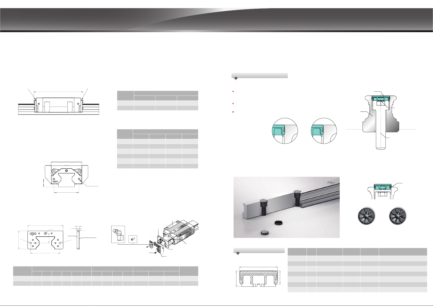
Low Friction Seals (B)
Our low-friction seals have slight contact with the rail
and are suitable for most environments, with both low
friction and a scraper function.
Standard Seals (S)
Our standard seals are in direct contact with the rail
surface, giving them increased dustproof and lubrication
retention capabilities. cpc recommends this class of seal
for blocks that operate in environments high in foreign
particles, such as sawdust, for long periods of time. S-type
seals will have comparatively higher friction than B-Type
seals.
Dust
Lubrication oil
B type S type
End Seals
End Seals
The end deals work in conjunction with the bottom and
inner seals to block foreign particles out and prevent
lubrication leakage. Our engineering plastic has a strong
friction resistance and is less prone to cracking than typical
NBR plastics.
Force of Friction
Time
Seal type friction comparison
Friction levels will be the highest on new linear rails. But,
after short periods of operation, such friction will be
reduced to a constant level.
Product Design (Standard)
Stainless Steel Reinforcement Plate
Dustproof design
Inner Seals
The newly designed inner seals both protect the rails
from foreign particles and keep the lubrication inside
the runner block while maintaining a low friction profile.
Bottom Seals
The bottom seals work in conjunction with the inner seals
to keep foreign particles out and lubrication from leaking
out. Our comprehensive sealing design significantly
reduces re-lubrication needs and prolongs the service life
of the runner block.
Inner seals
Bottom Seals
03 04
The reinforcement plate also functions as a scraper for
larger particulates like iron fillings, and has no more than
0.3mm clearance between the plate and the rail. ARC/HRC/ERC
VC
0.30 4
5
8
10
12
20
0.40
0.60
0.55
0.65
0.85
1.6 4.1 5.5
0.65
0.75
0.95
1.10
1.25
2.10
0.85
1.40
1.60
2.00
2.50
2.80
1.10
1.60
1.95
3.10
3.25
7.95
4.00
1.5
2.0
2.0
2.5
3.0
3.0
4.0
2.0
2.5
3.0
5.0
8.0
11.0
13.0
0.5
1.0
1.5
2.0
3.0
4.0
-
--
-
15MN/FN
20MN/FN
25MN/FN
30MN/FN
35MN/FN
45MN/FN
55MN/FN
V0 V1 V2
ARC/HRC/ERC
VC
0.30
0.40
0.50
0.50
0.60
0.70
0.90
1.00
0.80
1.10
1.20
1.80
1.00
1.40
1.80
2.30
1.5
2.0
2.5
3.0
2.0
2.5
3.0
5.0
0.5
1.0
1.5
2.0
15MS/FS
20MS/FS
25MS/FS
30MS/FS
V0 V1 V2
ARC/HRC/ERC
VC
0.40
0.50
0.70
0.80
0.90
1.00
1.9
0.70
0.80
1.20
1.40
1.60
2.30
4.3
0.90
1.60
1.80
2.20
2.70
3.50
6.6 8.6
1.40
1.80
2.00
2.80
3.50
4.55
1.5
2.0
2.0
2.5
3.0
3.0
4.0
2.0
2.5
3.0
5.0
8.0
11.0
13.0
0.5
1.0
1.5
2.0
3.0
4.0
15ML/FL
20ML/FL
25ML/FL
30ML/FL
35ML/FL
45ML/FL
V0 V1 V2
55ML/FL
4
5
8
10
4
5
8
10
12
20
Block Type
Block Type
Friction caused from ball bearing
Preload Class
Block Type
Friction caused from ball bearing
Preload Class
Bottom Seals +
Inner Seals S-Type
Standard
B-Type
Low friction
End Seals ( 2 sides )
External NBR seal with
metal scraper
Bottom Seals +
Inner Seals S-Type
Standard
B-Type
Low friction
End Seals ( 2 sides )
External NBR seal with
metal scraper
Friction caused from ball bearing
Preload Class Bottom Seals +
Inner Seals S-Type
Standard
B-Type
Low friction
End Seals ( 2 sides )
External NBR seal with
metal scraper
< 0.3mm
The following table shows the resistance value of the running block mounted with different seal types under the condition
when the running block lubricated with ISO VG32 lubricant.
Note: The end seal is made of elastic plastic material, not NBR, with low friction resistance and constant dynamic and static friction.

<pic.1>
Side Lubrication Port
(both sides of block have
lubrication holes)
LINEAR MOTION TECHNOLOGY
Product Design (Standard)
This test uses a total of 4 groups of products (2 rails matched with 2
lubrication methods) which are put on a saw wood dust surface on
which a back and forth motion test is performed.
Rail
Runner Block
Testing conditions
Installation Steps
1. Stroke = 600mm
2. Total testing stroke = 30m
Test items
1. If saw wood dust enters the inner surface of the runner block
2. If saw wood dust enters the ball bearing runner area
Test results
Tapped from bottom (oil) Tapped from bottom (grease)
Checked Item
Installation status
ARU Rail SZ Type Runner
Block (oil lubrication)
If saw wood dust
enters inner
block surface
If saw wood dust
enters ball bearing
runner area
ARU Rail S Type Runner
Block (grease lubrication)
AR Rail SZ Type Runner
Block (oil lubrication)
AR Rail S Type Runner
Block (grease lubrication)
No No
No No
No
No
Yes (belly area)
Yes (belly area)
Test result
ɓ!The standard rail has hole plugs, leading to rail unevenness, allowing some saw wood dust to enter the runner block belly
area. The 2 sides of the runner block belly area are completely protected by stainless steel reinforcement plates and end seals,
meaning that the ball bearing runner area is fully shielded from saw wood dust.
ɓ!The rail tapped from the bottom has an even rail surface so that the ball bearing runner area is fully protected from saw wood dust.
Saw wood dust
Runner block
Rail
Saw wood dust Test
Test content
Multi-Directional Lubrication Nozzles (All-direction Lubrication Nozzles)
Our product features lubrication ports on the top, bottom, and sides, allowing the installation of optional grease nipples for
relubrication. The top port comes with an O-ring seal to allow easy relubrication from the top, and our diverse comprehensive
lubrication injection design allows for lubrication from all directions.
Vmax >10 m/s Ĵmax >450m/s2
Using 2 stainless steel reinforcement plates, the L form
design allows for screws to be fastened onto the top
and bottom of the runner block, reinforcing the rigidity
and cladding of its caps.
The clearance between the rail profile with the seal
design is below 0.3mm, reinforcing the steel plates
while enabling scraper functions.
Our ARC/HRC/ERC, ARD/HRD/ERD type features stainless steel
reinforcement plates and additional bottom latches, increasing
its axial force and tolerance capacity to achieve a faster
operating speed.
F
Fx
Fy
Stainless Steel
Reinforcement
Plate
End Cap
Stainless steel reinforcement plate (Patent)
Scraping function on both sides
Function of high speed operation
05 06
1. Standard rail plus hole plugs (AR)
2. Rail tapped from the bottom (ARU)
1. Installation of standard contact type seals (S), using grease.
2. Installation of lubrication storage Pad and standard contact type
seals (SZ), using grease.
Fx
Fx
Fx
Instruction for side lubricant-nozzle-installation port of
Linear Guide
The side lubrication injection port (see pic.1) on cpc’s linear guide blocks is sealed
on delivery to prevent leakage of lubricants.
Before installing lubricant injection nozzle or piping, the seal must be broken to allow
lubricant to enter the runner block.
1. Tool
7RSLHUFHWKHVHDOVHOHFWDQDZOZLWKDGLDPHWHUOHVVWKDQǗPPVHHSLF
<pic.2>
2. Side lubrication port
The seal is in a deeper small hole in the middle of
the side lubrication injection hole on the block
(see Detail View A from pic.3). The seal is only 0.2
~0.3mm thick.
A
<pic.3>
<Detail View A>
Side lubrication
hole’s “seal”
3. Piercing method
Use the awl to stab into the seal showed in above picture. Press the awl against the seal (see pic.4A) and move gently forward by
about 1mm. Please do not use power tools or pierce too deep, to prevent damage to guide block end cap, which may impact its
functionality and interfere with lubricant passage.
<pic.4A> <pic.4B>
Sealed lubricant passage Cleared lubricant passage

LINEAR MOTION TECHNOLOGY
Product Design (Option)
2332km
10000 2000 3000 4000 5000 6000
-20 12 44 76 108 140 172 204 236 268 300
0
1.5
3
4.5
6
7.5
9
10.5
12
13.5
Condition
Model:ARC25MN SZC V1H Dynamic load rating C100Ȉ33.6kN
Velocity:1m/sec Stroke:960mm
Load capacities:7.44kN(0.3C) PreloadȈ0.05C
Rating Life()3 x 100km=()3 x 100km=2332km
-
P
C
-
0.05C+0.3C
C
With traditional ball type linear guides, the spinning of balls in different directions leads to a two-times faster contact speed.
Such high friction greatly reduces the service life of such products. Additionally, the contact point between such balls also
produces high pressure and noise levels while increasing the danger of oil film cladding damage.
Low noise ball chain
The contact point between the balls
and ball chain leads to a low
surface pressure level.
Traditional Ball type linear guide
Because the contact point of ball
type linear guides is only between
balls, the surface pressure is
significantly higher.
The
cpc
ball chain provides a greater contact area between the balls and the ball chain. Because the film cladding will not
be damaged easily and due to the lower noise volume, balls can move at a higher speed while product service life can also
be extended significantly.
*
*
The block with the ball chain design has the same dimensions as that without ball chains, allowing for the use of the same rails.
Heavy load test
Nominal life:
Travel distance (continuing):5877 km
Travel distance(km)
Smoothness test
Model code:ARC25MNSV1N
Velocity:10 mm/sec
Dynamic frictional (N)
Stroke(mm)
Ball chain
None ball
chain
After testing, grease remains
without anomalies.
Raceway surface
pitting
Low noise, superior quality high speed ball chain (Patent)
The table on the right shows the Ccage and
CISO values via different machine type testing.
(According to ISO-14728 regulations)
Mp/Mp0
My/My0
15
20
25
30
35
45
16.2
25.7
36.4
49.6
70.2
102.8
15
20
25
30
35
45
15
20
25
30
24.3
34.3
51.6
66.1
94.7
159.7
10.8
17.1
24.3
28.9
130
275
465
780
1575
2955
195
370
655
1040
1940
4185
85
185
310
455
95
200
340
530
1010
1775
215
350
640
900
1575
3280
45
85
145
205
95
200
340
530
1010
1775
215
350
640
900
1575
3280
45
85
145
205
Static rating load(kN) Static torque(Nm)
C
0
M
r0
M
p0
M
y0
1. The space block in the ball chain can prevent the oil film from rupturing by ball to ball contact and decrease friction induced wear.
2. The retainer block of the ball chain can maintain a reliable oil film layer by continuously applying grease on the moving part.
3. The ball chain provides the important function of leading steel ball motion. For traditional blocks without ball chains, its steel balls are
pushed by the rotating back steel balls on the raceway, meaning that the contact angle between the balls and rail is less precise,
causing vibration and an increased stress level between balls. In comparison, the balls in our ball chain product are led by the ball
chain to ensure a correct fit and accurate contact angles. In this way, our product's ball chain design ensures that it can fit
correctly when entering the raceway and that the contact angle will be accurate. This means that our Ball chain design provides
for a smooth performance, lower vibration levels and less additional stress levels. Subsequently increase the dynamic load rating,
Ccage value.
15
20
25
30
35
45
9.4
15.4
22.4
31.0
43.7
67.6
15
20
25
30
35
45
15
20
25
30
12.5
18.9
28.5
38.0
50.6
86.2
7.1
11.6
16.8
21.3
11.8
22.3
33.6
46.5
65.6
101.4
15.6
27.4
42.8
57.0
75.9
129.3
8.9
16.8
25.2
32.0
CISO (kN) Ccage(kN)
Ordering code: C
Load capacity of ball chain
There are three advantages of ARC/HRC/ERC/, ARD/HRD/ERD ball chain series as compared with traditional, non-ball chain blocks:
Model Code
Model Code
Dynamic rating load
Static rating load & Static torque
The C type block of ARC/HRC/ERC, ARD/HRD/ERD
will increase the pitch between balls on the
operating profile. Therefore, the static rating
load C0and the static rating torque Mr0, Mp0
and My0values will be decreased.
07 08
Ccage/C0Ccage/C0
Ccage/C0Ccage/C0
Mr/Mr0
ARC/ARD-MN C
ARC/ARD-FN C
HRC/HRD-MN C
HRC/HRD-FN C
ERC/ERD-MN C
ARC/ARD-ML C
HRC/HRD-ML C
HRC/HRD-FL C
ERC/ERD-ML C
ARC/ARD-MS C
ARC/ARD-FS C
ERC/ERD-MS C
ARC/ARD-MN C
ARC/ARD-FN C
HRC/HRD-MN C
HRC/HRD-FN C
ERC/ERD-MN C
ARC/ARD-ML C
HRC/HRD-ML C
HRC/HRD-FL C
ERC/ERD-ML C
ARC/ARD-MS C
ARC/ARD-FS C
ERC/ERD-MS C

LINEAR MOTION TECHNOLOGY
or
N2
N1
Ln
Product Design (option)
Upper Lubrication Storage Pad
Bottom Lubrication Storage Pad
Lubrication Design
Inner oil storage and oil supply system design
Our Inner PU Lubrication Storage Pad design does not increase the length of the runner block and
can effectively lubricate all balls. Customers can inject lubrication oil directly through its lubrication
holes to ensure sufficient storage in the PU Lubrication storage pad. This not only enables long-term
lubrication effects but also a higher degree of ease at conforming to environment protection needs
and lowering maintenance costs. For short-stroke movements, this product allows for highly effective
lubrication.
(Ordering Code: Z)
External NBR Seal with Metal Scraper (Ordering Code: SN / HN)
(ARC/HRC/ERC, WRC, ARD/HRD/ERD, ARR/HRR/LRR)
Available for applications in harsh environments such as in grinding, glass processing, graphite processing and wood-working machinery,
providing a highly effective dust and iron scrap proofing solution.
Stainless Steel
Rubber
Exterior Dimension Bore Specification Screw Specification
Model Code
Model Code
Model Code
Unit: mm
Unit: mm
Unit: mm
Nozzle Screw
External NBR Seal
External NBR Seal
(NBR/HNBR)
Block
Screw
Metal Scraper
Metal Scraper
Sleeve
Nozzle Sleeve
Guide Rail
Grease nipple
or
N2
N1
Ln
Nozzle Screw
External NBR Seal
Block
Screw
Metal Scraper
Sleeve
Nozzle Sleeve
Guide Rail
Grease nipple
Installation Manual
1. When installing the external NBR seal, please ensure that the block is
on the rail.
2. Ensure that the rubber part is fitted in the sleeve. If the rubber part has
fallen off, set the sleeve to the corresponding bore.
3. Overlap the rubber part and metal scrapper with the corresponding
salient point and bore. The
cpc
logo must be facing outward.
4. Slide the external NBR seal into the rail from two sides and closely
connect with the block.
5. Fasten the screw into the correspondence bore and align the seal
with the center of the rail and properly fastened. Do not allow the
metal scraper to make contact with the guide rail.
(ARC/HRC/ERC, ARD/HRD/ERD)
09 10
SN: (made by BRB) For application in harsh environment.
HN: (made by HNBR) For application of resisting acidic / basic coolant.
ARC/HRC/ERC ball type external NBR seal dimensions and specifications
P4S5N5g3
La
15
20
25
30
35
45
55
27/20
27/20
27/20
54.2
62.2
75.8
88
-
-
-
--
68.5
82
83
99.6
115.5
131.2
157.5
188.5
98.2
100.2
123.4
138
156.6
193.5
222
MS/FS MN/FN ML/FL
15
20
25
30
35
45
55
25
29
36.5
42.5
50
50
65
73
9.4
12.5
14.5
17
11
19.5
24
28.5
Dimensions of the block mounted with
external NBR seals
P
4
S
5
N
5
x g
3
15
T
4
6
6
6
6
4
5.2
1
1.5
1.5
1.5
1.5
1
1.2
3
4.5
4.5
4.5
4.5
3
413
4
33
58
68
84
98
61
41
47
10.2
17.5
20.5
24.9
28
11.5
11.5
13.5
3.5
4.5
4.5
4.5
5.5
3.5
3.5
3.5
3.5 M3x0.35 M3x0.5 A/B-M3-L
A/B-M3-L
A/B-M3-L
A/B-M6-L
A/B-M6-L
A/B-M6-L
A/B-M6-L
B-PT1/8-L
M3x0.5
M3x0.5
9
9
9
12
12
M3x0.35
M3x0.35
M3x0.35
M6x0.75
M6x0.75
M6x0.75
M6x0.75
PT1/8
M4x0.5
M4x0.5
M4x0.5
M5x0.5
M3x0.35
M3x0.35
M3x0.35
M3x0.35
M4x0.5
M4x0.5
M4x0.5
M5x0.5
2.3
2.1
2.5
2.8
3.2
3.1
5.8
5.6
6.5
6.5
6.5
10
3.5
3.5
6.5
20.3
34.2
39.3
49.6
57
22.5
23.2
26.5
t1t2P5
WH
3S6ØD1ØD2N1N2
20
25
30
35
45
55
12
12
15
Ln
Dimensions of external NBR seals
P
5
ØD
1
H
3
W
S
6
ØD
1
T
t
2
t
1
ØD
2
25
29
36.5
42.5
50
50
65
73
External NBR Seal with
Metal Scraper
External NBR Seal with
Metal Scraper
Exterior Dimension La
Exterior Dimension
Nipple
Extending the relubrication interval and reducing the amount of lubricant has always been the main issues for the manufacturers of linear guides.
The rolling elements and the raceway surface must be completely lubricated. This is the condition that the linear guide must have to operate.
However, the application environment of linear guides is quite different. A critical environment due to acid, iron filings, wood chips, coolant, working
speed, stroke length, load, installation, etc. will affect lubrication. The cpc lubrication storage can keep oil/grease for a long time. cpc block with the
lubrication unit can be used in the same way as the block without an oil tank. The grease nipple can be mounted on the block and the lubricant
can be supplied directly and achieves the effect of permanent lubrication!
The size and position of the screw hole on
the stainless steel reinforcement plate
Functions of the screw hole on the stainless steel reinforcement plate:
1. using for external NBR seal
2. using for the bellow
3. using for MSS reader
ARC/HRC/ERC
ARC/HRC/ERC
ARC/HRC/ERC
WRC
WRC
WRC
LINEAR MOTION TECHNOLOGY
ARR/HRR/LEE roller type external NBR seal dimensions and specifications
11
La
P
4
S
5
N
5
x g
3
P
5
!
ØD
1
H
3
W
S
6
ØD
1
T
t
2
t
1
ØD
2
12
C
H
ØD
(Ordering Code: MPC)
Cap can be Smoothly Installed on Bolt-Hole
The Most Convenient Metal Cap Used in Industry
Bolt-hole cap of conventional linear guides, due to the difficulty of controlling hammering strength, often result in caps being
hammered too deep or surface unevenness which leads to the accumulation of dirt or scrap iron. Our
cpc
cap is especially
designed with a supporting block to prop up the cap and to fix the screw stably, thus preventing such unnecessary sinking.
The upper part of the cap is made of stainless steel which can prevent
sharp foreign objects from piling up on the bolt-hole and affect the end
seal function.
The lower part of the cap is made of plastic, and can be installed directly
on a standard rail without the need for additional bolt-hole slot milling.
The bolt-hole chamfer for standard rails is C0.2mm. For further dustproof
requests, the non-bolt-hole chamfer rail is optional upon ordering. (order code: TR)
Metal Cap Features Introduction
Dimensions and Specifications
Metal-Plastic-Cap
Metal-Plastic-Cap
Rail
Supporting Block
Screw
Bolt-Hole with Chamfer
(standard)
Bolt-Hole without Chamfer
(optional: /TR)
Temporary
Support
Cap before
Hammering
(Plastic Support)
Plastic Support after
Hammering
(The form of the 8 supporting
blocks will become altered to
fit with the screw)
Block Height
C
A4
A5
A6
A8
A12
A8-R
M4
M5
M6
M8
M12
1.7 2.07.7
9.7
11.3
14.3
20.4
4.0
3.5
4.5
5.6
3.4
2.9
3.9
5.0
AR15 , WRC21/15, WRC27/20, ARR15
AR20 , ARR20
AR25 , ARR25
AR30 , AR35
M8 14.3 9.58.0 ARR35
AR45 , ARR45
Model Code Screw External Diameter
D
Cup Height
HRail
Metal-Plastic-Cap Patent Design for Standard Rail-Bolt-Hole
(With patent)
A14 M14 24.4 6.56.0 AR55 , ARR55
Stainless Steel
Rubber
or
N2
N1Screw
Ln
Nozzle Screw
External NBR Seal
Block
Metal Scraper
Sleeve
Nozzle Sleeve
Guide Rail
Grease nipple
T
6
6
1.5
1.5
4.5
4.5
69
84.9
60
70 22.9
20 4.5
4.5
M6x0.75 A/B-M6-XL
A/B-M6-XLM6x0.75
M4x0.5
M4x0.5
6.5
6.5
37.6
43.5
t1P5
t2WH
3S1S2ØD1ØD2N1N2
35
45
16
16
Ln
60
70
Exterior Dimension Bore Specification Screw Specification
Model
Code
Unit: mm
Nipple
External NBR Seal with
Metal Scraper
External NBR Seal with
Metal Scraper
Dimensions of the block mounted with
external NBR seals
The size and position of the screw hole on
the stainless steel reinforcement plate
Functions of the screw hole on the stainless steel reinforcement plate:
1. using for external NBR seal
2. using for the bellow
3. using for MSS reader
Dimensions of external NBR seals
35
45
142
176
167.5
211
197.5
246
MN/FN ML/FL MXL/FXL
Unit: mm
Unit: mm
Model
Code
Exterior Dimension La
P4S5N5g3
35
15
20
25
45
55
60
70
18
22.5
M4x0.5
M4x0.5
4.7
26 9.6 M3x0.35 1.4
29 12.5 M3x0.35 1.4
36.5 14 M3x0.35 1.7
3.3
3.576 27 M4x0.5
Exterior Dimension
Model
Code

LINEAR MOTION TECHNOLOGY
Basic static load capacity C0
The static load along the direction of the force; under this static load, the maximum calculated stress at the
center point of the contact surface between the ball and the track:
The value is 4200 MPa when radius of curvature ratio = 0.52
The value is 4600MPa when the radius of curvature = 0.6
Roller and rail contact surface produces the maximum calculated stress:
The value is 4000MPa
cpc's design of the roller guide series products has optimized the contact surface
between the roller and the raceway of the rail. The line contact stress is evenly
distributed. There is no edge stress effect, so they can withstand greater stress, as
shown in the right picture.
Note: At this point of maximum stress contact will yield a permanent deformation, which corresponds to 0.0001
diameter of the rolling element. (Above according to ISO 14728-2)
Static load safety factor calculation
(1) S0= C0/ P0
(2) S0= M0/ M
(3) P0= Fmax
(4) M0= Mmax
Equivalent static load P0and basic
static torque M0
Static load safety factor S0
The application of the static load capacity of the linear guide
series must be considered:
- Static load of linear guide
- Allowable load of screw fixation
- Permissible load of connected bodies
- The required static load safety factor for the application
The equivalent static load and static torque are the maximum
load and torque values, refer to equations (3) and (4).
In order to be able to withstand the permanent
deformation of the linear bearing and ensure that it
will not affect the accuracy and smooth operation of
the linear slide system. The static load safety factor S0
is calculated as equations (1) and (2).
S0 Static load safety factor
C0 Basic static load N in direction of load
P0 Equivalent static load N in direction of load
M0 Basic static torque Nm in direction of load
M Equivalent static torque Nm in direction of load
Operating situation S0
General operation
Shock or impact
High precision and smooth operation
1~2
2~3
≧ 3
13 14
Technical Information
Load capacity and service life
Definition: C100 is a radial load with constant magnitude and direction; when the linear bearing is
subjected to this load, its rated life can theoretically reach a walking distance of 100 kilometers,
and C50 is a walking distance of 50 kilometers. (Above according to ISO 14728-1)
According to ISO 14728-1 for the bearing steel used in the current technology, the calculated life
span of 90% survival rate for a single or batch of sufficient and identical linear bearings under normal
manufacturing quality and normal operating conditions is as follows:
C100
P
Ĵ
3
10
L >!rated life
C100 /C50!>!Dynamic Load Rating!)N*
P!!>!equivalent load!)N*
When using a ball type linear guide!!Ĵ= 3
When using roller linear guide !Ĵ=
(5) L = •105
C50
P
Ĵ
L = •5 x 10⁴
Please refer to equations (6) and (7) for a comparison of the basic rated load capacity defined by the
two types of basic load capacity conversion when the standard rated load capacity C50 is taken as the
standard when the 50 km distance is taken as the rated life. (according to ISO14728-1)
(6) C50 = 1.26•C100
(7) C100 = 0.79•C50
Ball
(8) Lh= =
2•s•n•60 vm•60
LL
According to the operating velocity and frequency, the service distance can be converted to service life, assuming
the equivalent load and average velocity are constant.
Lh!>!Rated life!)h*
L >!Rated life for walking 100 km!)m*
s!!>!Single stroke )m*
n!!>!Frequency of reciprocating stroke!)min-1*
Vm!!>!Average velocity!)m/min*
If the block alone experiences the torque from Mp and My direction, the maximum allowable torque
for the block to run smoothly is 0.2 to 0.3 times static torque. And the block with larger preload would
have larger maximum allowable torque and vice versa. When static torque Mp and My is larger than
maximum allowable torque, the jumping of the block will be caused when the ball is rolling through the
loaded / unloaded region in the block. If you have above mentioned design problem, please contact
our technical department.
When the block alone experiences the torque
Ccage is a basic dynamic load capacity value of block with ball chain, which is 120 to 130% of the CISO value according
to the practical test (see Page 8). Formulas (5), (6), and (7) also apply to C100/cage and C50 / cage
Basic dynamic load capacity CISO (general design) /
Ccage (ball chain design )
CISO:C100 /C50
Pcpc
PCylindrical roller
Pmax
Raceway surface
Stress
LINEAR MOTION TECHNOLOGY
15 16
v =
q1•v1 + q2•v2 +...+qn•vn
100
(10)
When the velocity changes, the equivalent velocity is calculated according to formula (10).
v!!>!equivalent velocity!)m/min*
q!>!portion of working distance per segment (%)
When the load and velocity all change, the equivalent load is calculated according to formula (11).
P = Ĵ
ĴĴ Ĵ
q1•v1•F1 + q2•v2•F2 +...+qn•vn•Fn
100
(11) v
3
10
P >!!equivalent load!)N*
When using ball-type linear guide!!Ĵ= 3
When using roller-type linear guide!!Ĵ=
q!>!percentage of walking distance per segment!)%*
v!!>!velocity of each segment!)m/min*
F1!>!load per segment!)N*
When the linear guide is subjected to any angular load and the direction of the force other than the horizontal
or vertical direction, the approximated value of equivalent load is calculated as (12).
3 ɕ)Xɕɕ)Yɕ
(12)
P >!equivalent load!!)N*
FX!!>!force at horizontal component!)N*
FY!!>!force at vertical component!)N*
When the linear guide experience both load and torque at the time, the approximated value of equivalent
load is be calculated by formula (13)
3 ɕ)ɕɕ0ɕ•
(13) 00
C0
P >!equivalent load!)N*
F!!>!ORDGDSSOLHGWRWKH/0JXLGH!)N*
0!!>!static torque!!)Nm*
C0!!>!basic static load direction!)N*
00!!>!basic static torque in direction of force )Nm*
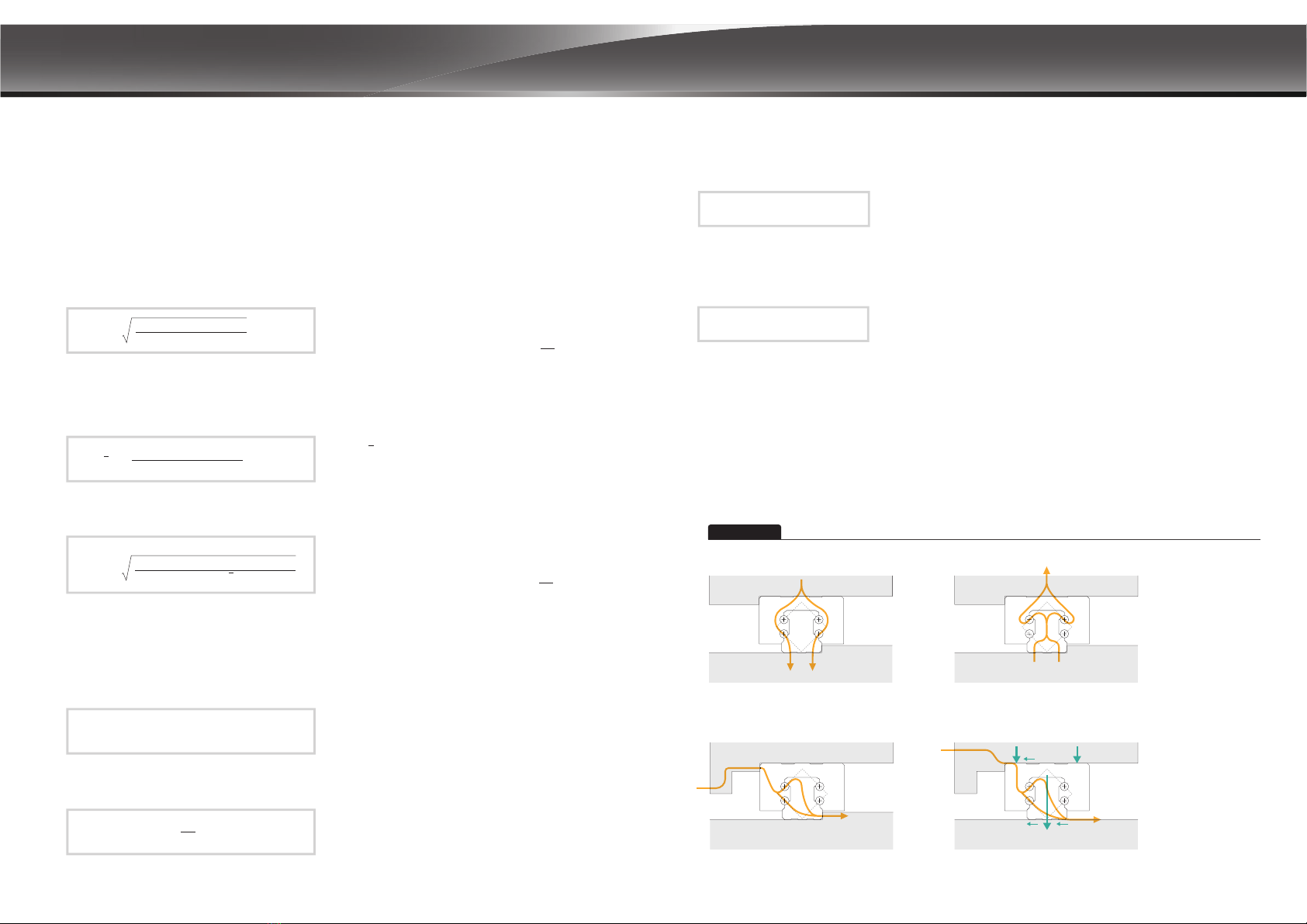
In general, the loads on the linear guide exert on the four major planes. However it can be the load from any angle.
In this case, the life of the linear guide is reduced. This can be interpreted by the flow of forces inside the system.
Line chart
As can be seen from the three diagrams in Figure A to Figure D, when subjected to upward, downward and lateral
loads, the force flow will be distributed to the two ball transfer.
Figure A
Lateral force 1 Lateral force 2
Figure B
Figure C Figure D
Under pressure Pull up
Ff1
Ff2
FS2
FS1
FS1、FS2:screw fixation
Ff1、Ff2:frictional
resistance
Ff= FS•Ǎ0
Equivalent load and Velocity
When the load and velocity are not constant, all actual loads and velocities must be considered, and it will impact the service life.
For each segment of each block, when the load changes, the equivalent load is calculated according to formula (9).
P = Ĵ
ĴĴ Ĵ
q1•F1 + q2•F2 +...+qn•Fn
100
(9)
3
10
P >!equivalent load!)N*
When using ball-type linear guide!!Ĵ= 3
When using roller-type linear guide!!Ĵ=
q!>!portion of working distance per segment (%)
F1!>!load per segment!)N*
Load capacity and life
Technical Information Operating temperature range
Friction
The linear guides have stable and constant running friction and slight start-up friction, which brings out the properties of the
product's low frictional resistance to the full.
Frn = μ· F Frn!>!Friction!)N*
F >!Load!)N*
Friction Factors
- Sealing system
- Collision between rolling elements and rolling
elements during operation
- Collision of the rolling elements with the return path
- Resistance caused by the rolling and sliding phenomenon at
the contact point of the rolling element and the raceway of
the rail
- Resistance caused by the squeezing of lubricant when the rolling
elements running
- Resistance caused by contaminations
Ý&aÝ&
7KH5OOHU*XLGH6HULHVIULFWLRQIDFWRULVDSSUR[ a
The Linear Guide Series have a permissible operating temperature between -40 °C
DQG&DQGWKHPD[LPXPWHPSHUDWXUHIRUVKRUWWHUPRSHUDWLRQFDQUHDFK&
Friction

LINEAR MOTION TECHNOLOGY
17 18
As shown in the two diagrams in Figures E and F, the load acting on the 45-degree angle has the greatest effect on the system's
life because the transfer of force is limited to a single row of balls.
When the load is applied horizontally or vertically (0 Ý, 90 Ý, 180 Ý
, 270 Ý), the equivalent load of the slide is equal to the actual
load. When the load angle is 45 , its equivalent load is approximately
1.414 times that of the main direction. (as shown in formula (12))
Ý Ý
Ý
Ý
Ý
Ý
Ý
Ý
Ý
Ý
Ý
Ý
Ý
Ý
Ý
Ý
Ý
Ý
Ý
Ý
Ý
Ý
Ý
Ý
Actual equivalence
load
Equation (12) (Page 15) calculates the
approximate value of the equivalent load
0
0.5
1.5
1.0
Therefore, in order to increase the service life of the linear system,
it should be installed in the appropriate direction to bear the load.
Otherwise, the service life will be greatly reduced, as shown in the
figure below. Since the relationship between life and load is as the
power of formula (5), when the acceptance angle is 45Ý, the service
life will be significantly reduced.
Ý Ý
Ý
Ý
Ý
Ý
Ý
Ý
Ý
Ý
Ý
Ý
Ý
Ý
Ý
Ý
Ý
Ý
Ý
Ý
Ý
Ý
Ý
Ý
10%
0%
20%
30%
40%
50%
60%
70%
80%
90%
100%
Ball Roller
The following is the life L comparison chart (in %) for different angles
under the same load.
When the same load is at different angles, the comparison of
equation (12) and the actual equivalence load is as shown in the
following figure.
Ý Ý
Load calculation
1. The load exert on the linear guide would varies due to the position of object’s center of gravity, thrust position and acceleration /
deceleration induced inertia.
2. Because of the uneven distribution of force on linear guide, when a certain part of rail, or when a force exertion point is damaged,
the linear guide system would start to malfunction.
3. The point with largest force exertion must be identified, and be used reference to calculate the equivalent load, to ensure the
reliability of service life calculation.
Q ןF ( Dw2 ȂDž2ȂCDž
2 ) Q ן)DžןȂleff
ǃ)
Ball Roller
Q = !load
Dž !amount of rolling element
deformation
Dw = ball diameter
CDž= geometric constant
Q = load
Dž= amount of rolling element
deformation
leff = contact length
Q = load
Dž amount of rolling
element deformation
As shown by the formula, the relationship between the amount of
deformation of the rolling element and load is not linear. A larger
deformation will cause the non-linear increase of load.
Therefore by using the cpc self-developed program, the “Loading, Lifetime, & Rigidity Analysis Software of Linear Guide System
(LLRAS)”, a precise service life estimation can be derived. This is done by optimum calculation of deformation and rotation when
a linear guide experience load, in this case the accurate equivalent load can be calculated.
1 3 3
-
The following is a comparison diagram of the equivalent load approximate value and the actual equivalent load calculated by
Equation (13). The example uses the ARC25MN linear guide to withstand a fixed down pressure and the torque gradually increases.
The above figure shows the torque in the Mr direction. The figure below shows the torque in the Mp/y direction.
0
5
10
15
20
25
30
35
40
0 50 100 150 200 250 300 350
(kN)
(Nm)
Actual equivalence load Actual equivalence load
0
5
10
15
20
25
30
35
40
45
50
0 100 200 300 400 500 600
(kN)
(Nm)
˖!!˖•C0
Mr
Mr0 ˖!!!!˖•C0
Mp/y
Mp0/y0
Load capacity and life
Line chart
Figure E Figure F
(Equivalent load)
(Equivalent load)
(Mrdirection torque) (Torque in Mp/y direction)
Equation (13) (Page 15) Calculate the approximate
value of the equivalent load
Equation (13) (Page 15) calculates the approximate value of
the equivalent load
Q
Dž
Technical Information

LINEAR MOTION TECHNOLOGY
19 20
2. Set the carriage size model
Variables can be set:
- Block span
- Block type
- Block preload
1. Set the slide rail position, the number of slides on the slide
Variables can be set:
- Linear guide span
- Linear guide height
- Linear guide placement angle
- Platform inclination
- Number of block
3. Set the exercise state
4. Set external force and torque position, size, direction
Variables can be set:
- Working status
- Drive position
- Actuation frequency
Variables can be set:
- External force (torque) intensity
- External force (torque) position
- External force (torque) working
zone
Loading, Lifetime, & Rigidity Analysis Software of Linear Guide System (LLRAS)
Data input guidance
Technical Information

LINEAR MOTION TECHNOLOGY
6. Check if the settings are correct from the 3D chart
The calculation results are shown in the figure, and the information such as force and equivalent load, safety factor, and life span of
each section can be obtained, and the deformation of any measured point can also be obtained.*
This program can be used to calculate the installation and dimension design of various linear slide rails under different load and
movement conditions. The obtained information such as deformation amount, force distribution, and life span can help to provide
appropriate and correct design recommendations.
* For the calculation of amount of deformation, only the rolling object is considered. For actual deformation the steel body of block
must be considered as well. When the load > 20% C0, the actual deformation is 1.5 times larger than calculated deformation.
When Load = C0, the actual deformation is 2~2.5 times of calculated deformation.
5. Set the quality position size
Variables can be set:
- Center of gravity position
- Center of gravity
dimension
- Load range
21 22
Using the ARC 25 MN VC block, the schematic diagram of the mechanism is as follows:
Motion status is as follows
Traditional calculated results obtained by geometric distribution.
cpc
Results calculated by program
Application Example
Centroid position 100kg Centroid position 100kg
2 m/s2-2 m/s2
0.5
250mm 500mm 250mm
1.0 1.5
1
V (m/s)
T (sec)
At acceleration
At constant velocity
At deceleration
Average load
Block 1
348.6
384.0
419.4
385.9
348.6
384.0
419.4
385.9
914.5
949.9
985.3
951.0
914.5
949.9
985.3
951.0
Block 2 Block 3 Block 4 Block 1
220
245
270
220
245
270
711
736
761
711
736
761
736
Block 2 Block 3 Block 4
In this case, the calculated result of equivalent load is 30% higher than result obtained by traditional geometric distribution method,
and the service life is about 2 times different.
If there is a demand for life and rigidity calculation, please fill in form of 【Linear guide service life calculation and model selection】
and contact cpc technical department.
Block 1 & Block 2
Block 1 & Block 3 Block 2 & Block 4
Block 3 & Block 4
400
200 300
200
50
50
The maximum value
of average load
Drive position Drive position
Loading, Lifetime, & Rigidity Analysis Software of Linear Guide System (LLRAS)
At acceleration
At constant velocity
At deceleration
Unit:N Unit:N
Technical Information
LINEAR MOTION TECHNOLOGY
23 24
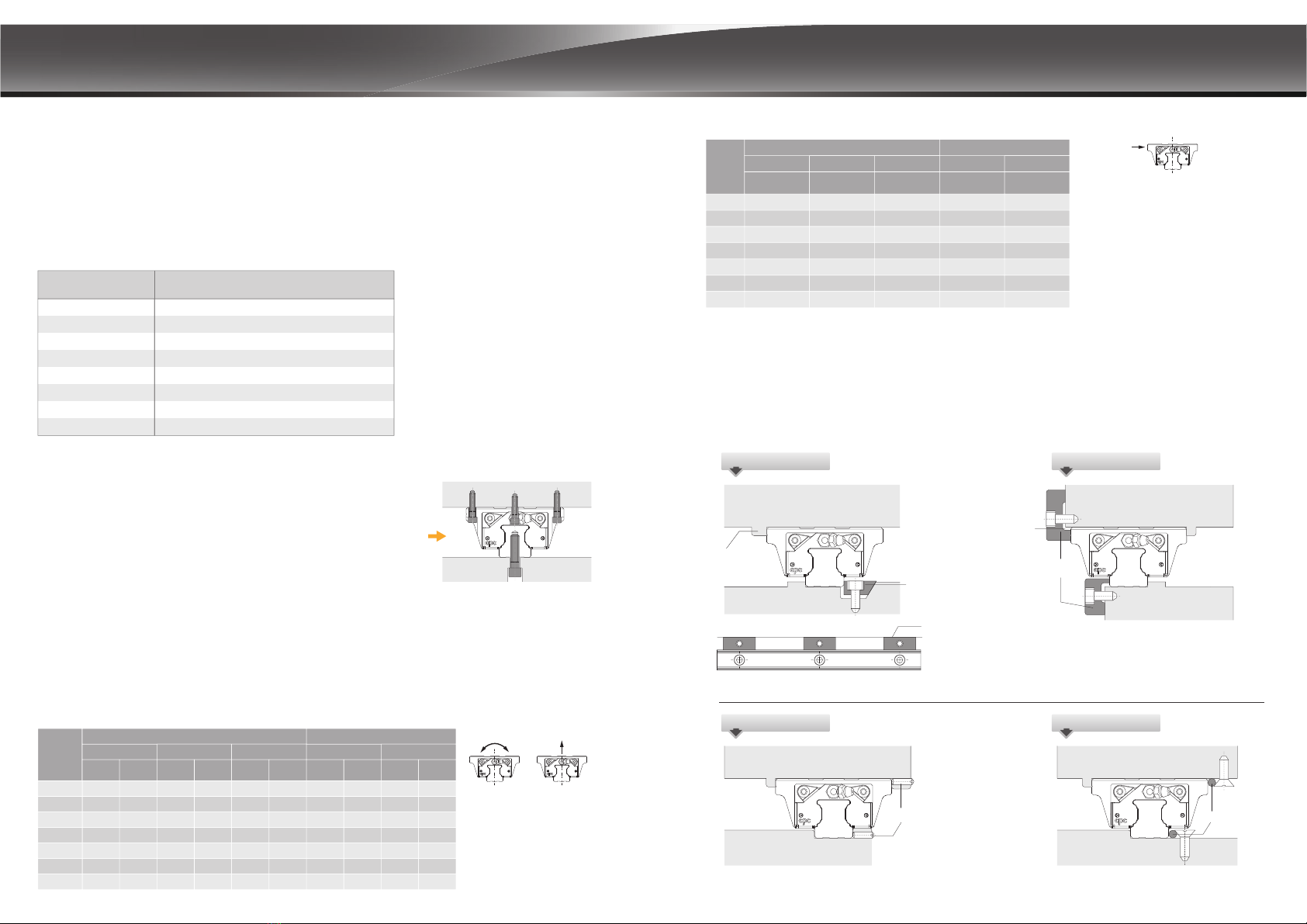
Lateral bearing surfaces and lateral fixing elements
When the lateral load is greater than the lateral load capacity, the lateral bearing surface is required to bear the lateral force. If the
lateral force is bidirectional, Lateral fixing elements can be used to provide a bidirectional lateral load capability of the linear guide
on the other side of the side bearing surface, and help close to the lateral bearing surface, the lateral straightness and side load
capacity after installation will be greatly improved, and its allowable value will vary according to the type of fixed component.
The following diagram shows several common elements.
Wedge block
Wedge block
Open slot
Binder plate
Mandrel
The linear guide rail is tightened by locking the
bolts on the wedge block.
The open slot must be machined to prevent
interference between the linear guide and carriage
on the corners during installation.
When the installation space is limited, the size of lateral
mounting element must be considered.
Use the slope of the nut to advance the roller
to achieve the effect of tightening the linear
LM guide.
Socket set screws
Linear guide often experience lateral load when used; in the case of mounting screw
only, the lateral bearing capacity is suggested to be determined by the static friction
force resulted from the screw tightening torque. If the maximum lateral load is exceeded,
the support from the edge, lateral mounting and plugs are possible options to enhance
the load capacity.
The lateral bearing capacity (without support from edge and
lateral mounting)
Screw tightening torque (Nm)
Strength grade 12.9
Alloy steel screws s teel cast iron Non-ferrous metals
M3 2.0 1.3 1.0
4.1 2.7 2.1
8.8 5.9 4.4
13.7 9.2 6.9
30 20 15
118 78 59
157 105 78
M4
M5
M6
M8
M12
68 45 33M10
M14
Lateral bearing
surfaces
The maximum bearing capacity of linear guide is not only related to the static load capacity C0, but also the screw mounting of
coupling parts. Factors such as length of block, distance between rails, size of screws, and contact width of rail would impact
the maximum bearing capacity of screw mounting.
Socket set screws Mandrel fixing
Binder plate
Wedge block
Fmax
FZ,max
N
FZ,max
N
FZ,max
N
FZ,max
N
FZ,max
N
Mt,max
Nm
Mt,max
Nm
Mt,max
Nm
Mt,max
Nm
Mt,max
Nm
15 3200
5500
8100
15900
-
-
-
22
51
87
210
-
-
-
26
60
100
240
300
970
1600
30
68
120
280
340
1100
1800
50
115
190
470
590
1900
3200
60
134
240
560
680
2200
3600
3700
6400
9400
18500
18500
45900
63700
4200
7300
10800
21100
21100
52400
72800
7200
12500
18700
36900
36900
91700
127400
8000
14500
21000
42200
42200
104800
145600
20
25
30
35
45
55
Screw maximum tensile strength and torque
According to DIN637, DIN SIO 12090-1 and DIN EN ISO 898-1 regulation, when the tensile strength, torque and lateral force exert on
class 8.8 alloy steel screw is larger than the values in table below, the screw mounting and design of edge support must be revised
to avoid loose.
Mt,max
FZ,max
Screw lateral bearing capacity
Fy,max
When class 10.9 class alloy steel screw is used, the value is about 1.4 times larger than the value in table above.
When 12.9 class alloy steel screw is used, the value is about 1.68 times larger.
Fy,max
N
Fy,max
N
Fy,max
N
Fy,max
N
Fy,max
N
15 240
410
610
1200
-
-
-
280
480
710
1400
1400
3400
4800
320
550
810
1600
1600
3900
5500
550
950
1400
2800
2800
6900
9600
630
1050
1600
3200
3200
7900
11000
20
25
30
35
45
55
size
ball type
short standard long standard long
roller type
ball type
short standard long standard long
size
roller type
Technical Information

LINEAR MOTION TECHNOLOGY
25 26
ARC/ARD/WRC
VC 0
0.02CV0
V1
V2
Preload and clerance
The ARC/HRC/ERC, ARD/HRD/ERD linear guides provide 4 different preload classes VC, V0, V1, V2.
Class Description
ǍP
Clearance
Application
Clearance
Light
Preload
0HGLXP
Preload
Heavy
Preload
Preload
Value 15
WRC21/15 WRC27/20
+5~+0 +5~+0 +5~+0 +5~+0 +5~+0 +5~+0 +5~+0
+5~+0 +5~+0 +5~+0 +5~+0 +5~+0 +5~+0 +5~+0
20
25 30 35 45 55
6PRRWKPRWLRQ
low friction
For precision situations,
VPRRWKPRWLRQ
High stiffness, precision,
high load situations
Super high stiffness,
precision and load
capacity
HRC/ERC/HRD/ERD
VC
V0
V1
V2
Class Description
ǍP
Clearance Application
Clearance
Light
Preload
0HGLXP
Preload
Heavy
Preload
Preload
Value 15 20 25 30 35 45 55
6PRRWKPRWLRQ
low friction
For precision situations,
VPRRWKPRWLRQ
High stiffness, precision,
high load situations
Super high stiffness,
precision and load
capacity
0
0.02C
0.05C
0.08C
0.08C
0.13C
+0~-4 +0~-5 +0~-6 +0~-7 +0~-8 +0~-10 +0~-12
-4~-10 -5~-12 -6~-15 -7~-18 -8~-20 -10~-24 -12~-28
-10~-16 -12~-18 -15~-23 -20~-31 -24~-36 -28~-45-18~-27
+0~-4 +0~-5 +0~-6 +0~-7 +0~-8 +0~-10 +0~-12
-4~-12 -5~-14 -6~-16 -7~-19 -8~-22 -10~-25 -12~-29
-12~-19 -14~-23 -16~-26 -22~-35 -25~-40 -29~-46-19~-31
1B 1B1A 1A
P/2 P/2
P/2 P/2
Figure B
Figure A
Installation Notice
'LPHQVLRQRIUHIHUHQFHHGJH
Rail Joint
7RHQVXUHWKDWWKHOLQHDUJXLGHLVSUHFLVHO\DVVHPEOHGZLWKWKHPDFKLQHWDEOHcpc devices have a recess installed in the
UHIHUHQFHHGJHFRUQHU7KHFRUQHURIWKHPDFKLQHWDEOHPXVWEHVPDOOHUWKDQWKHFKDPIHURIWKHOLQHDUJXLGHWRDYRLG
LQWHUIHUHQFH7RFRQVXOWRQFKDPIHUVL]HVDQGVKRXOGHUKHLJKWVSOHDVHUHIHUWRWKHWDEOHEHORZ
7KHVWDQGDUGOHQJWKRIRXUODUJHUDLOVLVPHWHUV,IORQJHUUDLOVDUHUHTXLUHGcpc can provide a joint rail solution for which the joint
QXPEHUZLOOEHPDUNHGRQWKHUDLO
$VVKRZQLQILJXUH$SOHDVHIROORZWKHMRLQWQXPEHUWRDVVHPEOH
2. )RUPRUHWKDQWZRXQLWVLQHDFKD[LVWRDYRLGDFFXUDF\HIIHFWVIURPPXOWLSOHEORFNVSDVVLQJWKURXJKWKHVDPHFRQQHFWLRQSRLQW
we advise to use the connection points separately as shown on figure B.
3. 3OHDVHXVHWKHVOLGHDVDFRQQHFWLRQSRLQWWRWLJKWHQWKHVOLGHEHIRUHWLJKWHQLQJWKHWRUTXHVWRIDVWHQWKHVFUHZVIURPLQVLGHWRRXWVLGH
section
separation of guideway connection points
section
h2
E
r2PD[
h1
r1PD[
2SHUDWLQJ7HPSHUDWXUH
7KH/LQHDU*XLGH6HULHVRIVWDQGDUGEDOOJXLGHZLGHEDOOJXLGHDQGUROOHUJXLGHVKDYHDSHUPLVVLEOHRSHUDWLQJWHPSHUDWXUH
EHWZHHQ&DQG&DQGWKHPD[LPXPWHPSHUDWXUHIRUVKRUWWHUPRSHUDWLRQFDQUHDFK&
7HFKQLFDO,QIRUPDWLRQ
Unit:PP
15 0.5
0.5
1.0
1.0
1.0
1.0
1.5
0.5
0.5
1.0
1.0
1.0
1.0
1.5 10.0 10.0 12.0
3.3
5.0
6.0
6.6
7.6
9.3
2.5
4.0
5.0
5.5
6.5
8.0
r1PD[ r2PD[ h1h2E
20
25
30
35
45
55
4.0
5.0
5.0
6.0
6.0
8.0
ARC/HRC/ERC, ARD/HRD/ERD
21/15
27/20
0.4
0.4
0.4 2.7
3.5
2.0
3.0
r1PD[ r2PD[ h1h2E
5.0
0.4 5.0
WRC
35
15
20
25
0.5
0.5
1
0.5
0.5
1
4
5
5
2
3.4
4
2.9
4.4
5
45
1
1
16
8
5
7
r1PD[ r2PD[ h1h2E
8
0.5 10
1.5 1081.5 10
55
ARR/HRR/LRR
Type
Type
Type

LINEAR MOTION TECHNOLOGY
Installation surface geometry position
accuracy
27 28
d
e2
The rough finishing or milling on installation site will impact
the working accuracy of linear guide, and reduce the service
life of both standard, wide ball type linear guide and roller type
linear guide. The accuracy of installation site and linear guides
are critical factors to determine the accuracy of work bench.
When the error of installation site is larger than the value
calculated by following formula, the working resistance and
service life will be impacted.
Installation datum plane
Rail: Both edges of rail can be reference edge, it shouldn’t
be marked separately.
Block: The side steel body of the block with
1. milled surface
2. Without groove mark can be the reference side.
Applicable to 15-55 all models
Installation instructions
e3
//
b
e1
VC
5.2
43.1 29.7 18.3 8.9
4.8
3.1
10.5
7.3
17.5
12.3
26.0
18.4
4.5
4.2
3.5
3.1
2.8
2.2
1.8
1.7
1.1
0.8
0.7
1.3 1.1 1.0 0.8
1.2 1.1 0.9 0.7
1.2 1.0 0.9 0.7
V0 V1 V2
MS / FS
MN / FN
ML / FL
ARC/HRC/ERC (f1)
VC V0 V1 V2
MN / FN
ML / FL
MXL / FXL
ARR/HRR/LRR (f1)
VC V0 V1 V2
MS / FS
MN / FN
ML / FL
ARC/HRC/ERC (f2)
VC V0 V1 V2
7.1 6.2 5.2 4.3
5.3 4.7 3.9 3.2
4.2 3.6 3.0 2.5
MN / FN
ML / FL
MXL / FXL
ARR/HRR/LRR (f2)
VC
20 14
14
13
12
9
8
7
5
4
3
12
15
14
13
8
6
18
17
23
21
30
28
15
7
8
8
11
10
10
15
13
8
16
10
9
6
5
4
18
22
22
20
28
27
25
35
32
46
44
24
16
18
16
25
23
21
31
27
38
37
35
49
45
65
62
33
31
V0 V1 V2
ARC (f3)
VC V0 V1 V2
15 MN / FN / FN-R
15 ML / ML-R / FL / FL-R
20 MN / FN / FN-R
20 ML / ML-R / FL / FL-R
25 MS
25 MN / FN / FN-R
25 ML / ML-R / FL / FL-R
30 MN / FN / FN-R
30 ML / ML-R / FL / FL-R
35 MN / FN / FN-R
35 ML / ML-R / FL / FL-R
45 MN / FN / FN-R
45 ML / ML-R / FL / FL-R
55 MN / FN / FN-R
55 ML / ML-R / FL
15 MS / FS
15 MN / FN
15 ML
20 MS / FS
20 MN / FN
20 ML
25 MS / FS
25 MN / FN
30 MS / FS
30 MN / FN
35 MN / FN
45 MN
30 ML
35 ML
45 ML
55 MN
55 ML
HRC / ERC (f3)
18
16
13
12
8
7
4
3
16
14
10
9
5
4
23
21
31
27
25
22
20
18
15
13
11
8
6
5
33
31
24
22
15
14
8
7
8
8
37
35
27
25
17
16
49
45
65
62
35
32
23
21
46
44
30
28
11
10
15
13
V0 V1 V2
11 7 4
10 7 3
10 6 3
13 9 4
12 9 4
11 8 3
45 MN / FN
45 ML / FL
45 MXL / FXL
55 MN / FN
55 ML / FL
55 MXL / FXL
ARR/HRR/LRR (f3)
ྤ৴לԒ
V0 V1 V2
96 3
54 2
53 2
75 2
75 2
75 2
65 2
64 2
85 2
85 2
35 MN / FN
35 ML / FL
35 MXL / FXL
25 MN / FN
25 ML / FL
25 MXL / FXL
15 MN / FN
20 MN / FN
15 ML / FL
20 ML / FL
ARR/HRR/LRR (f3)
Block length
Block length
Block length
Block length
Block length
Block length
Block length
Block length

LINEAR MOTION TECHNOLOGY
29 30
Lubrication
unit :cm3unit :cm3
unit :cm3
unit :cm3
unit :cm3unit :cm3
Function
Rail installation
Recommended precision measurement method
Diagram FeatureDescription
ȆNo Straightening
ȆNot allowed
•Straightening by pin
•Not suggested
•Straightening based on
straight edge, calibrated
by meter
•With support edge and
lateral mounting screw
No precision
Low lateral bearing capacity
Low precision
Low lateral bearing capacity
Low to mid precision
Low lateral bearing capacity
High precision
One side with high lateral
bearing capacity
Very high precision
High lateral bearing capacity
on both sides.
LL
h1h2
The working accuracy of linear guide is defined by the parallelism between block and rail(height, side). In practical application
the linear accuracy is required, the measuring method is diverse, so we would suggest following measure to acquire the linear
accuracy of linear guide.
H The horizontal working accuracy +
base plane flatness ɕK
1
-h
2
ɕ
total length
( above mentioned method can be used to exclude the skew error
of rail on roll direction)
AB
W
2
The horizontal working accuracy +
the straightness of rail installation
(Please refer to table of working precision page 31 ) (Please refer to table of working precision page 31 )
* When the error of flatness of base plane is 0, the value is the
linear working accuracy of rail at the certain height
A
B
Installation instructions
straightedge
straightedge
straightedge
*When the error of the straightness of the rail is 0, the
value is the horizontal working accuracy on the side.
•Place the rail on a
supporting edge
(Precision vise applied) Precautions when lubrication with oil
1. If indicate "oil lubrication" on the order, the carriage provided will not be pre-filled with grease.
2. If the block already has grease inside and the grease is different from the grease set by the customer or has exceeded the 12-month
shelf life, you must clean the block before assembling. Test the lubricants to avoid grease incompatibility. Ensure that the channel
is free, and the lubricant can flow to the rolling elements and be lubricated.
3. If using the grease nipple combined with the tubing kit or the set screws for the lubricating oil inlet channel, must wrap it with a tapseal
to achieve a leakproof effect.
ARC/HRC/ERC, ARD/HRD/ERD
15 1.4 2
4
7
10
16
32 37
19.5
12.5
9
5
2.5
2.3
3.9
5.9
-
-
-
1.2
2.3
3.9
5.4
-
-
-53
3.2
5.5
9.5
14
21
40
66.5
1.5
3.5
7
9
15
30
--
20
25
30
35
45
55
15
20
25
30
35
45
55
Size
21/15
27/20
2.2
4.8
WRC
21/15
27/20
2.7
5.3
ARR/HRR/LRR
15
20
15
20
-
25
30
-
35
45
16.2
22
18.0
3.7 4.5
6.1 7.2
9.5 10.8
26.4
21.3
11.9
12.4 13.7 15.1
55
30.8
31.2 38.5 46.8
-
-
25
35
30
45
14.7
20.8
16.5
3.1 3.9
5.0 6.3
24.3
19.8
8.5 9.7 10.8
11.2 12.5 13.9
27.7
55 30.6 37.8 46
ARC/HRC/ERC, ARD/HRD/ERD (ball chain type)
Size short (S) standard (N) long (L) Size short (S) standard (N) long (L)
WRC (ball chain type)
standard (N)Size standard (N)
Size extra long (XL)standard (N) long (L) Size extra long (XL)standard (N) long (L)
ARR/HRR/LRR (roller chain type)
Lubrication methods and note on lubrication
1. The block already contains lubricants that can be directly installed on the machine without additional cleaning.
2. If cleaning of the block is required which the oil storage is equipped, please wait until the cleanser and clean naphtha in the oil
storage are dry, and then put the block in lubricating oil, so that the oil storage can absorb enough lubricating oil before it will be
installed in Machine.
3. Before the first start-up, the carriage and the rail must be protected by adding lubricating grease and contact with liquid or solid
contaminants must be avoided.
4. The cpc block is provided with lubrication holes at the front and rear ends, as well as left and right and on the top. The grease can
be injected into the block through the holes. The amount of grease required for a single block is given in the table below.
5. The block must run back and forth while lubricating.
6. Must consistently provide an oil film on the surface of the rail, which is easily noticeable optically.
7. If dry and discolored, relubrication should be carried out immediately, and the relubrication interval should be determined according
to the environment and conditions of use.
8. The user must inform in advance if it is used in a cleanroom environment or requires acid and alkali resistance.
9. If the use of a guide deviates from the horizontal installation, the use of oil lubrication must be carefully checked.
10. The re-lubrication interval must be shortened if the travel stroke is < 2 or > 15 times the length of the steel body of the runner block.
11. If the stroke is less than two times the steel body of the block, the grease must be injected through the lubrication hole from the left
and right of the block and then run on a rail that is at least three times the length of the block to distribute the grease evenly in the
block. Repeat this step twice.
12. For the central lubrication system, cpc recommends the use of liquid grease NLGI 00 or NLGI 000.
When operating the linear guides under sufficient lubrication, a one-micron layer of the oil film at the contact zone separating the
loaded rolling elements and the raceway.
Sufficient lubrication will:
- Reduce the friction - Minimize wear - Prevent oxidation - Dissipate heat and increase operating life.
Space for grease in the block inside

LINEAR MOTION TECHNOLOGY
31 32
Tolerance of dimension width W2
Variation of height for different
runner blocks on the same
position of Rail
Accuracy
Application
Technical information Ordering information
Customization code(The meaning of suffix characters)
:slide rail connection
:customer designated lubricant
:with Inspection report
J
:special straightness requirements for rail
S
G
I
:special processing for block
B
:with plastic caps for counter holes
on the rail
PC
:with Metal-Plastic Caps for rail
mounting holes.
MPC
:with extension and contraction support
layer.
BL
:external NBR seal with metal scraper
SN :external HNBR seal with metal scraper
HN
:black chrome coating treatment
on the rail
BR
:black chrome coating treatment
on the block
BB
:with stainless steel ball bearings
SB
:reference edges of block and rail on
opposite sides
DE
:customized designated preload
pressure value
VD
:clear chrome coating treatment on
the rail
CR
:clear chrome coating treatment on
the block
CB
:nickel coating treatment on the rail
NR
:raydent coating treatment on
the rail
RR
:raydent coating treatment on
the block
RB
:nickel coating treatment on the
block
NB
:raydent coating treatment on
the block and rail
RRB
:clear chrome coating treatment on
the block and rail
CRB
:block install with grease nipple by cpc
OA
:installation of side grease holes
and set screws
SG:special process for rail
:bolt-Hole without chamfer
TR
R
:black chrome coating treatment
on the block and rail
BRB
:nickel coating treatment on the
block and rail
NRB
Note: For special process or customized requirement, please contact cpc for more information.
( Please contact cpc for direction of grease nipple
installation)
(Available for size 15,20,25,30,35 and 45)
ARC 15 N -RMB2ZCV1P /JII-20-20-1480LU
R: six mounting holes
Customization code
End hole pitch (mm)*
Starting hole pitch (mm)*
Rail length (mm)
Accuracy grade : UP, SP, P, H, N
Preload class : VC, V0, V1, V2
C: with ball chain
Z: with lubrication storage pad
Block quantity
Seal type : B: Low friction S: Standard
Block length : L: long N: standard S: short
Block width : M: standard F: flanged
Block type : 15, 20, 25, 30, 35, 45, 55
U: rail ( tapped from the bottom)
Number of rails on the same
moving axis
Product type : ARC: automation series HRC/ERC: heavy load series
Unlabeled: Standards
* The end pitch of the rail should not exceed the 1/2 of original pitch, this is to avoid the misfit of the rail to
the workbench.
N
H
P
SP
UP
The ARC/HRC/ERC, ARD/HRD/ERD, WRC linear guides provide 5
different grades of precision : N, H, P, SP, and UP, Engineers can
choose different grades depending on the machine applications.
Accuracy
Size
15 ~ 20
25 ~35
45 ~ 55
UP SP P H N
Ʀ+
H
W2
Ʀ:2
± 5
± 5
3
3
± 10
± 7
5
5
± 15
± 10
6
7
± 30
± 20
10
15
± 70
± 40
20
30
± 5
± 5
3
3
± 10
± 7
5
5
± 20
± 10
7
7
± 40
± 20
15
15
± 80
± 40
20
30
± 5
± 5
3
3
± 10
± 7
5
5
± 20
± 10
7
7
± 40
± 20
15
15
± 80
± 40
25
30
Ʀ+
H
W2
Ʀ:2
Ʀ+
H
W2
Ʀ:2
$FFXUDF\JUDGHVǍP
Tolerance of dimension height H
Variation of width for different
runner blocks on the same
position of Rail
Tolerance of dimension width W2
Variation of height for different
runner blocks on the same
position of Rail
Tolerance of dimension height H
Variation of width for different
runner blocks on the same
position of Rail
Tolerance of dimension width W2
Variation of height for different
runner blocks on the same
position of Rail
Tolerance of dimension height H
Variation of width for different
runner blocks on the same
position of Rail
Runner block relative to linear guide, datum plane parallel motion precision
running parallelism
rail(mm)
class Movement,
Conveyance Manufacturing
Equipment
High Precision
Manufacturing
Equipment
Measuring
Equipment
Examples
1. Conveyance system
2. Industrial robots
3. Office Machinery
1. Woodworking machine
2. Punching press
3. Injection Molding machine
1. Lathe/milling machine/
grinding machine
2. Electrical discharge
machining (EDM)
3. CNC machining center
1. Three dimensional
measuring instrument
2. Detection mirror / head shaft
3. X-Y Table
L0 ± 1mm
L2 ± 0.5mm PL3 ± 0.5mm
0.4
Butt-jointing is required when lengths exceed Lmax.
(For more detailed information, please contact cpc for technical support.)
Length of Rail

N3
S4
N3
S4
ød
H1
N2N2
øD
L1L1
LL
EE
g1
P
S3S3P1
S2
S2
W
P2
W1W2
M
N1
H
g2
h2
T
S1
LINEAR MOTION TECHNOLOGY
MS MN / ML
Mp/Mp0
My/My0
C/C0C/C0
C/C0C/C0
Mr/Mr0
The above rating load capacities and static moments are
calculated according to the ISO14728 standard. The rating life
for basic dynamic load ratings is defined as the total 100km
travel distance for 90% of a group of identical linear guides,
under the same conditions and free from any material damage
caused by rolling fatigue. If a standard of 50km travel distance
is applied to measure the average product lifespan, the above
basic dynamic load rating C should be multiplied by 1.26 for
an accurate conversion.
1. The load capacities is for full-ball type (without ball chain)
2. N2= Injecting holes
3. N3= O-ring size for lubrication from above
4. N2 ,N3 will be sealed before shipmant, please open it when first using the product.
5. Please refer to the catalog P10 for the size of the screw hole of the reinforcement sheet
Suitable for
!
_RC_ _MN/MLSuitable for
!
_RC_ _MS
Dimensions Table
33 34
ARC 15 MS
ARC 20 MS
ARC 25 MS
ARC 30 MS
ARC 15 MS
ARC 20 MS
ARC 25 MS
ARC 30 MS
1290
2280
3020
4380
24
28
33
42
15
20
23
28
15
20
23
27
60 7.5x4.5x5.3
9.5x6x8.5
11x7x9
14x9x12
60
60
80
34
42
48
60
26 M4x7
M5x7
M6x9
M8x12
32
35
40
6 M3x6.5
M3x7.5
M6x7.5
M6x8.5
M3x6 5.3
10
12
12
4.5 7.5
7.4
9.3
12
16.7
19.8
23.2
26.7
7.7
12.5
18.2
23.3
12.1
19.3
27.3
33.1
205
350
520
100
100 50
160
230
170
106
300
560
15.6
19.1
22.2
27
4
5
7.5
M3x5.5
M3x6.5
M6x5
8
8
12
12
41.2
49.2
57.4
68
26 -
-
-
-
-
-
-
-
32.2
38.4
44
20.7
23
27
35.2
9.5
11
12.5
16
ARC 15 MN
ARC 20 MN
ARC 25 MN
ARC 30 MN
ARC 35 MN
ARC 45 MN
ARC 55 MN
ARC 15 MN
ARC 20 MN
ARC 25 MN
ARC 30 MN
ARC 35 MN
ARC 45 MN
ARC 55 MN
48
60
34
45
32
39
14x9x12
20x14x17
80
105
70
86
M8x13
M10x17
26
32
35
40
50
50
60
60
M6x10
M6x10
PT1/8x12.5
12
14 18.1
15
10.9 9.9
17.1
24.8
32.8
45.9
71.3
17.5
30.0
42.5
53.7
82.9
122.1
140
325
540
845
1700
3200
105
230
385
565
1080
1910
158
266
420
800
1120
2120
4200
3160
1536
186 4949 3278
13.7
17.6
20.5
24.1
27.3
9.8
13
16.6
20.8
23.4
27.3
8
11.1
M6x7
M6x10.5
14
14
55.5
69
81.2
95.5
111.2
135.5 102.5
40.3
-
-
M12x20 M6x1316-
52
62.2
71.5
86.2 40.4
50.7
100 75
75168.5 126.5 58
20.5
70 53 45.7 24x16x2012023.5
18
12 23.5 10833.834.8
13.5
6790
10530
14000
ARC 30 ML 118
136.6
171.5
94
61
111.6
138.5
60
72
80
21.7
25.1
35.3
21.7 39.6
54.7
70.2 1105
2185
950
1755
1138
106.5
89.5 4430 3460
100
50
160
230
105
230
385
565
1080
1910
3278
950
1755
3460169.1
25.8
35.3
ARC 35 ML
ARC 45 ML
ARC 30 ML
ARC 35 ML
ARC 45 ML
P3
P4
P4
P5
ARC 15 ML
ARC 20 ML
ARC 15 ML
ARC 20 ML
34
45
17.2
20.4
13.4 26.9
38.5
215
415
235
390
240
33016.3
16.1
15.6
76.2
87.2 70.2
235
390
P5
P5
P5
5083202 160 95
-
-
-
ERC 25 MS ERC 25 MS36 12.3 23.2 18.2 27.3 350 160 31522.2857.4 -38.4 30 160
-
-
-
-
41.5 125 6472 5284 528422640.5ARC 55 ML ARC 55 ML
HWLPDxdx
g
1
Mxg
2
W
2
h
2
W
1
L
1
M
1
P
1
P
2
P
3
H
1
N
2
S
2
S
1
C
0
Mr
0
Mp
0
My
0
C
S
3
S
4
N
3
N
1
TE
0
-0.05
ARC/ERC MS, MN, ML Series
Model Code
Mounting
Dimensions Rail Dimensions(mm) Block Dimensions(mm) Block Dimensions(mm)
Model Code
Load Capacities
(KN) Static Moment (Nm) Weight
Block (g) Rail (g/m)

LINEAR MOTION TECHNOLOGY
36
Mp/Mp0
My/My0
C/C0C/C0
C/C0C/C0
Mr/Mr0
W1W1
M1
M1
W2W2
N1N1
Mxg2
Mxg2
H
H
h2
h2
T1
T1
T
T
S1
S1
WW
P2P2
Suitable for ARC 15 FS
ȃ
FN
ARC 20 FS
ȃ
FN
ARC 25 FS
ȃ
FN
Suitable for ARC 30 FS
ȃ
FN
ARC 35 FN
N3
S4
N3
S4
S2
S2
H1
N2N2
øD
S3S3P1
L1L1
LL
EE
ød
g1
P
FS FN
ARC FS, FN Series
The above rating load capacities and static moments are
calculated according to the ISO14728 standard. The rating life
for basic dynamic load ratings is defined as the total 100km
travel distance for 90% of a group of identical linear guides,
under the same conditions and free from any material damage
caused by rolling fatigue. If a standard of 50km travel distance
is applied to measure the average product lifespan, the above
basic dynamic load rating C should be multiplied by 1.26 for
an accurate conversion.
1. The load capacities is for full-ball type (without ball chain)
2. N2= Injecting holes
3. N3= O-ring size for lubrication from above
4. N2 ,N3 will be sealed before shipmant, please open it when first using the product.
5. Please refer to the catalog P10 for the size of the screw hole of the reinforcement sheet
Suitable for ARC _ _FS Suitable for ARC _ _FN
Dimensions Table
35
ARC 15 FS
ARC 20 FS
ARC 25 FS
ARC 30 FS
ARC 15 FS
ARC 20 FS
ARC 25 FS
ARC 30 FS
24
28
33
42
15
20
23
28
15
20
23
27
60 7.5x4.5x5.3
9.5x6x8.5
11x7x9
14x9x12
60
60
80
52
59
73
90
41
49
60
72
M3x6.5
M3x7.5
M6x7.5
M6x8.5
M4
M5
M6
M8
M3x6 5.3
10
12
12
4.5 7.5
7.4
9.3
12
16.7
19.8
23.2
26.8
210
132
345
750
15.6
19.1
22.2
27
4
5
7.5
M3x5.5
M3x6.5
M6x5
41.2
49.2
57.4
68
26 -
-
-
-
32.2
38.4
44
20.7
23
27
35.2
18.5
19.5
25
31
1290
2280
3020
4380
ARC 15 FN
ARC 20 FN
ARC 25 FN
ARC 30 FN
ARC 35 FN
ARC 15 FN
ARC 20 FN
ARC 25 FN
ARC 30 FN
ARC 35 FN48 34 32 14x9x1280 100
26
32
35
40
8250 M6x10M8 12 15
8.9 200
336
524
1200
1580
13.7
17.6
20.5
24.1
10.9
13
16.6
20.8
23.48M6x7
55.5
69
81.2
95.5
111.2
40.3
52
62.2
71.5
86.2 40.433 6790
P3
P4
P4
P5
P5
7.7
12.5
18.2
23.3
12.1
19.3
27.3
33.1
205
350
520
100
100 50
160
230
100
50
160
230
9.9
17.1
24.8
32.8
45.9
17.5
30.0
42.5
53.7
82.9
140
325
540
845
1700
105
230
385
565
1080
105
230
385
565
1080
-
-
-
-
-
M5x7
M6x10
M8x10
M10x12
7
10
12
12
7
10
10
12
M10x13 13 13
C
0
HWLPDxdx
g
1
Mxg
2
W
2
h
2
W
1
L
1
M
1
P
1
P
2
P
3
H
1
N
2
S
2
S
1
Mr
0
Mp
0
My
0
C
S
3
S
4
N
3
N
1
TT
1
E
0
-0.05
Model Code
Mounting
Dimensions Rail Dimensions(mm) Block Dimensions(mm) Block Dimensions(mm)
Model Code
Load Capacities
(KN) Static Moment (Nm) Weight
Block (g) Rail (g/m)
This manual suits for next models
9
Table of contents
Popular Industrial Equipment manuals by other brands

ABB
ABB HT575655 Operation manual

Balluff
Balluff BTL7-S5-M-A-SA360-KA-ZA10 Series Condensed guide

Dodge
Dodge Sleevoil STL 9 PLAIN instruction manual

Festo
Festo EXCM-10-150 Mechanical installation

schmersal
schmersal AZM201B-I2-SK-T-1P2PW-A Instructions for operation

Tisch Environmental
Tisch Environmental TE-5000-BL Operation manual


Appleton
Appleton FSQC 100 Installation & maintenance instructions

schmersal
schmersal AZM201Z-I2-ST2-T-SD2P-A-DU Instructions for assembly and operation

Dustcontrol
Dustcontrol TSR 43 Original instructions

Scotchman
Scotchman IRONWORKER 6509-24M manual

igus
igus e-chainsystems installation guide

Daikin
Daikin ESRH02A6 installation manual