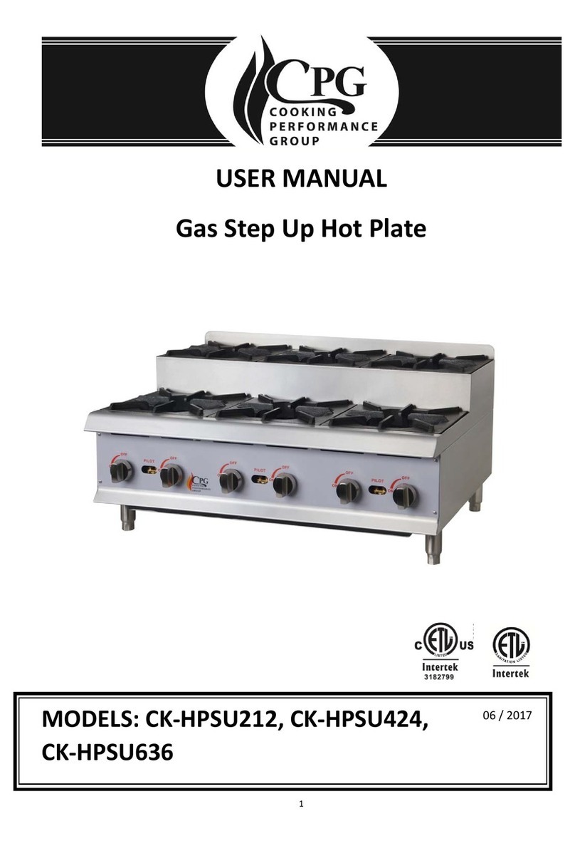
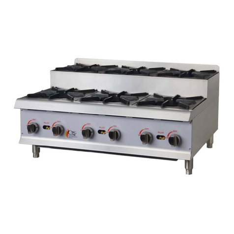
CPG ULTRA Series User manual

USER MANUAL
Gas Countertop
Chrome Plated Griddles
with Thermostatic Controls
CHROME PLATED GRIDDLE MODELS:
NATURAL GASLIQUID PROPANE
REVISED 3/2020
351GTUCPG24L
351GTUCPG36L
351GTUCPG48L
351GTUCPG60L
351GTUCPG72L
351GTUCPG24N
351GTUCPG36N
351GTUCPG48N
351GTUCPG60N
351GTUCPG72N
24" Wide
36" Wide
48" Wide
60" Wide
72" Wide

2www.CookingPerformanceGroup.com
USER MANUAL
FEATURES AND SPECIFICATIONS
• Durable stainless steel construction
• ⁄” thick chrome plated cooking surface
• Independent, controlled cooking zones
• 30,000 BTU stainless steel “U” shape burners
• Each burner has a continuous pilot for instant ignition
• Full 20” depth plate provides greater cooking surface
• Removable, full width waste tray
• Heavy duty adjustable feet
• ⁄” rear gas connection
NOTE: Depth DOES NOT include regulator (3.25") size.
CONTENTS
Features & Specifications .............................. 2
Safety Precautions .................................... 3
Serial Plate ........................................... 3
Installation Instructions................................ 4
Gas Connection....................................... 5
Cooking with a Chrome Plated Griddle ................. 6
Lighting Instructions .................................. 6
Seasoning Griddle .................................... 7
Operating Instructions................................. 7
Temperature Guide & Useful Accessories................ 7
Cleaning & Maintenance ............................... 8
Troubleshooting ...................................... 9
Parts Diagram ......................................10-11
Congratulations on your purchase of Cooking Performance Group commercial cooking equipment!
At Cooking Performance Group, we take pride in the design, innovation, and quality of our products.
When used as intended and with proper care and maintenance, you will experience years of reliable
operation from your Cooking Performance Group equipment. To ensure optimal performance, we have
outlined the following instructions and guidelines in this manual carefully for your review.
MODEL DIMENSIONS
(W x D x H)
PLATE
THICKNESS
# OF
BURNERS POWER PRESSURE
(") W.C.
NET
WEIGHT
GROSS
WEIGHT
351GTUCPG24 /L /N 24" x 29.3" x 16.3" ⁄" 2 60,000 BTU 6" NG/10" LP 159 lb. 189 lb.
351GTUCPG36 /L /N 36" x 29.3" x 16.3" ⁄" 3 90,000 BTU 6" NG/10" LP 226 lb. 269 lb.
351GTUCPG48 /L /N 48" x 29.3" x 16.3" ⁄" 4 120,000 BTU 6" NG/10" LP 299 lb. 359 lb.
351GTUCPG60 /L /N 60" x 29.3" x 16.3" ⁄" 5 150,000 BTU 6" NG/10" LP 363 lb. 441 lb.
351GTUCPG72 /L /N 72" x 29.3" x 16.3" ⁄" 6 180,000 BTU 6" NG/10" LP 430 lb. 522 lb.

www.CookingPerformanceGroup.com 3
USER MANUAL
CLEARANCE REQUIREMENTS:
Combustible Sides: 6”
Combustible Back: 6”
Serial # 1101000001
Conforms to ANSI STD Z83.11-2016 and certified to CSA 1.8 STD- 2016
Conforms to NSF / ANSI STD. 4
Made in China
Item # 351GTUCPG24N
Model # G24T
GRILL COUNTER 24" THERM
Total BTU: 60,000
Gas Type: Natural gas
Manifold Pressure: 6 in.w.c
Orifice Size: # 41
SAFETY PRECAUTIONS
CAUTION: Potential hazard or unsafe practice could result in minor or moderate injury and product or
property damage.
NOTICE:
• Local codes regarding installation vary greatly from one area to another. The National Fire
Protection Association, Inc., states in its NFPA96 latest edition that local codes are “Authority
Having Jurisdiction” when it comes to requirement for installation of equipment. Therefore,
installation should comply with all local codes.
• This product is intended for commercial use only. Not for residential use.
WARNING:
• Do not store or use gasoline or other flammable vapors and liquids in the vicinity of this or any
other appliance.
• Improper installation, adjustment, alteration, service, or maintenance could lead to property
damage, injury, or death. Read the installation, operating, and maintenance instructions
thoroughly before installing or servicing CPG equipment. This manual must be retained
for future reference.
• Instructions must be posted in a prominent location. All safety precautions must be taken in the
event the user smells gas. Safety information can be obtained from your local gas supplier.
• A factory authorized agent should handle all maintenance and repair. Prior to conducting any
maintenance or repair work contact an authorized service agency.
GAS PRESSURE:
The appliance and its individual shuto valve (to be supplied by user) must be disconnected from the
gas supply piping system during any pressure testing of that system at test pressures in excess of
⁄ PSI (3.45 kPa). The appliance must be isolated from the gas supply piping system by closing its
individual manual shut-o valve during any pressure testing of the gas supply piping system at test
pressures equal to or less than ⁄ PSI (3.45 kPa).
SERIAL PLATE
NOTE: The serial plate is located
on the right side of the unit.

4www.CookingPerformanceGroup.com
USER MANUAL
INSTALLATION INSTRUCTIONS
THESE UNITS ARE SUITABLE FOR INSTALLATION ON NON-COMBUSTIBLE
SURFACES ONLY. DO NOT INSTALL NEAR ANY COMBUSTIBLE SURFACES.
IMMEDIATELY INSPECT FOR SHIPPING DAMAGE:
All containers should be examined for damage before and during unloading. The freight carrier has
assumed responsibility for its safe transit and delivery. If equipment is received damaged, either apparent
or concealed, a claim must be made with the delivering carrier.
Apparent damage or loss must be noted on the freight bill at the time of delivery. It must then be signed
by the carrier representative (ie: driver). If this is not done, the carrier may refuse the claim. The carrier can
supply the necessary forms.
Concealed damage or loss if not apparent until after equipment is uncrated, a request for inspection
must be made to the carrier within 15 days. The carrier should arrange an inspection. Be certain to retain
all contents and packaging material.
Installation and service should be performed by an authorized service agency. If you have questions
concerning the installation, operation, maintenance, or service of your equipment, visit CPG’s website at
www.CookingPerformanceGroup.com.
Make sure that the floor where you plan to locate the griddle is capable of supporting its weight along with
any accessories. Adequate clearance should be provided for proper operation and servicing. Level the
griddle once you’ve uncrated it in your facility using the adjustable feet.
Proper ventilation is crucial to safe and optimum performance. Ensure that the griddle is installed
underneath a ventilation hood according to all applicable local and national codes. Keep adequate
clearance for air openings into the combustion chamber.
COMBUSTIBLE CLEARANCE REQUIREMENTS: 6" Sides • 6" Back

www.CookingPerformanceGroup.com 5
USER MANUAL
GAS CONNECTION
NOTE:
This griddle ships from the factory configured for areas with an altitude that is lower than 6,500 feet.
1. Ensure gas supply and gas type, as shown on unit serial plate agree. Unit installation must conform
with the National Fuel Gas Code, ANSI Z223.1/NFPA 54, the National Gas Installation Code, CSA-B149.1,
or the Propane Installation Code, CSA-B149.2 as applicable and in accordance with local codes.
2. A manual gas shut-o valve must be installed in the gas supply line ahead of the appliance and
gas pressure regulator for safety and ease in servicing.
3. The gas pressure regulator supplied must be installed on the appliance prior to connecting the
equipment to the gas line. Failure to install a regulator could be potentially hazardous and will
void limited equipment warranty.
4. Pipe threading compound must be resistant to the eects of liquefied petroleum gases.
CAUTION: DO NOT use an open flame to check for leaks. Check all gas piping for leaks with a soap and
water solution prior to operating unit.

6www.CookingPerformanceGroup.com
USER MANUAL
ADJUSTING PILOT LIGHT
1. Turn o the manual valve and wait 5 minutes to clear gas.
2. Turn all knobs to “OFF” position.
3. Hold an ignition source (match) at pilot. When the flame is established, remove ignition source.
4. Turn burner knobs to “ON”. If the burner does not ignite, promptly open pilot valve more.
If pilot flame appears larger than necessary, turn it down and reset burner ignition.
The pilot flame should be as small as possible but large enough to guarantee reliable ignition
of burners when knobs are turned to “ON”.
LIGHTING INSTRUCTIONS
The pilot light on the griddle has been pre-set at the factory. A screwdriver may be required for the initial
lighting to adjust the flame for your elevation.
COOKING WITH A CHROME PLATED GRIDDLE
Your new CPG chrome plated griddle has excellent heat retention and heat transfer as well as minimal
flavor transfer. CPG has created a griddle that oers a reduction in energy costs and clean up time,
translating into a great deal of profit savings.
Since the chrome plated griddle has such a high level of heat retention, it acts as a heat shield that does
not allow as much upward radiation, creating a cooler work environment. The significant amount of heat
retained on the chrome griddle also allows for a rapid heat transfer, which produces faster cook times at
lower temperatures.
Unlike steel plate griddles, the chrome plate on the griddle prevents food particles from getting trapped
on the cooking surface, thus preventing flavor transfer. In other words, your pancakes for breakfast will
not taste like last night's salmon.
LIGHTING PILOT LIGHT:
1. Select the burner required, depress and turn the corresponding gas control knob
counter-clockwise to “PILOT” position.
2. With the gas control knob depressed, manually light pilot burner.
3. Release gas control knob approximately 10-20 seconds after lighting pilot burner.
4. Pilot burner should stay lit. Provided it does not, repeat steps 2 and 3.
5. Rotate gas control knob counter-clockwise to desired temperature mark.
6. The main burner will now be ignited automatically.
NOTE: If you want the pilot to remain ON:
DO NOT move the knob back towards "OFF" from the pilot.
If you want to extinguish the pilot:
Turn the knob back to the "OFF" position.

www.CookingPerformanceGroup.com 7
USER MANUAL
NOTE: Seasoning is not required, but the below procedure may be done to improve
the non-stick qualities of the cooking surface.
1. Heat the griddle to a 300-350°F (150-180°C) and pour on a small amount of cooking oil,
about 1 oz. (30cc) per square foot of surface.
2. Spread the oil over the entire griddle surface with a cloth to create a thin film.
3. Wipe o any excess oil with a clean lint free cloth.
4. Repeat this procedure 2 times.
1. Turn the burners on to the desired temperature for about 15-20 minutes before cooking
for preheating. We recommend the operating temperature for a chrome griddle to be
10-15°F lower than standard griddles. Start with lower temperatures and increase as necessary.
2. If dierent temperature settings are to be used, adjoining areas should be set at progressively
higher temperatures using the lowest temperatures on the outside burners.
3. Upon completion of each batch of food, scrape the work area of the griddle clean with
the blade scraper.
SEASONING GRIDDLE
OPERATING INSTRUCTIONS
• The finish on chrome-plated griddles is delicate and must be handled with care. Be sure to follow
suggested guidelines for care and maintenance to prevent voiding the warranty.
• Please note that the griddle is NOT intended for use where the surface will be hacked, hit,
cut, or chopped on. DAMAGE CAUSED BY THIS IS IRREPARABLE.
TEMPERATURE GUIDE
USEFUL ACCESSORIES
Bacon
Eggs
(over easy/medium
& scrambled)
Grilled
Cheese
Hamburger
Patty Pancakes Salmon Sausage
325°F 250-275°F 325°F 325-350°F 360-370°F 325°F 315-325°F
ITEM # DESCRIPTION
470M35110BK 12" Black High Temperature Slotted Turner
92284120BK 13½" High Heat Nylon Slotted Turner
147GRIDDLKLN 32 oz. Liquid Grill/Griddle Cleaner
181GS6 Heavy-Duty Aluminum Grill Scraper
407WDWB020 Natural Non-Scratching Sti Bristled Brush

8www.CookingPerformanceGroup.com
USER MANUAL
CLEANING & MAINTENANCE
INITIAL CLEANING:
1. Prior to operating your new griddle, heat the griddle to 200-300°F to loosen and melt any
coating that was applied to the griddle at the factory.
2. Add water or Noble Chemical Griddle Kleen cleanser to the surface and use the blade scraper
to remove the oil residue.
NOTE:The only scraper that should be used is the razor blade style provided.
Other types may nick the surface.
3. Rinse and dry with a lint free cloth.
DAILY CLEANING:
1. Clean the plate while still hot between 300-350°F.
2. Scrape griddle plate with blade scraper.
3. Pour water (or for heavy duty cleaning, Noble Chemical Griddle Kleen cleanser) on the surface
and immediately scrub the griddle with a natural non-scratching sti bristle brush.
4. Sweep the water or cleanser into the trough drain at the front of the griddle.
5. Wipe o and polish the surface with a clean lint free cloth and polish solution suitable for
chrome griddles.
6. Rinse with water to remove any excess polish.
NOBLE CHEMICAL GRIDDLE KLEEN
•Fast-acting formula quickly removes grease and other buildup.
• Can be used on a pre-heated surface for even greater results.
• Non-flammable for the best in safety and peace of mind.
• Easy application helps ensure eective cleaning by even inexperienced workers.
• Available in 32 oz. bottles and 3 oz. QuikPacks
CAUTION: CHROME PLATED GRIDDLES ARE DELICATE PIECES OF EQUIPMENT
RECOMMENDED CLEANING AGENT
• USE Recommended accessories (page 7).
• DO NOT use a griddle stone, brick, or screen.
Damage caused by these utensils is irreparable.
• DO NOT use ice to cool the surface of the
griddle. This may cause warping.
• DO NOT use a power washer, jet, hose,
or steam cleaner.
• DO NOT hit, chop, hack, or cut on the
griddle plate.

www.CookingPerformanceGroup.com 9
USER MANUAL
NOTICE: The above examples are provided for your reference. Provided a failure occurs, stop using,
and consult an authorized service agency. All maintenance should be done after the power supply and
gas supply are shut o.
TROUBLESHOOTING
PROBLEM POSSIBLE CAUSES SOLUTIONS
Heat does not come on
when the thermostat or
burner valve is on.
Pilot burner not lit. Light and adjust pilot burner (pg. 6).
Griddle shut-o valve not in ON position. No solution necessary.
Gas valve malfunction. Replace the gas valve.
Pilot burner will not
light.
Pilot valve turned o. Turn the pilot valve on. (pg. 6)
Obstructed pilot orifice. Clear obstructions from the pilot orifice.
Pilot gas turned o at the pilot. Adjust pilot to permit gas flow.
Pilot burner will not
stay lit.
Obstructed pilot orifice Clear obstructions from the pilot orifice.
Gas supply is not purged of air. Purge gas supply of air (pg. 5).
Air is blowing pilot light out. Turn any fans away from the broiler or move
to a less breezy location.
Fat appears to smoke
excessively.
Heat is set too high. Turn heat down.
Moisture in the food may be turning into steam. No solution necessary.
Food sticks to the
griddle, or burning
around edges.
Heat is set too high. Turn heat down.
Griddle surface needs to be cleaned and/or re-seasoned Clean and/or re-season griddle surface (pg. 7)
Griddle surface needs to be oiled. Oil griddle surface with appropriate food oil.
Food is undercooked
inside.
Heat is set too high or too low.
If cooked on the outside, turn heat down
and increase cook time.
If undercooked on the outside, turn heat up
and increase cook time.
Food may not have been cooked for long enough time. Increase cook time.
Food tastes greasy or
has an objectionable
o-flavor
Food itself may have o flavor. Check raw product for freshness.
Food may have been stored improperly before cooking. Check storage containers and use by dates.
Too much fat used. Use less fat.
Heat is set too low. Turn heat up.

10 www.CookingPerformanceGroup.com
USER MANUAL
PARTS DIAGRAM
MODEL:351GTCPG72NL
# DESCRIPTION MODEL CODE QTY
1 BURNER
351GTUCPG24 /L /N
06.05.1470672
2
351GTUCPG36 /L /N 3
351GTUCPG48 /L /N 4
351GTUCPG60 /L /N 5
351GTUCPG72 /L /N 6
2 REGULATOR ALL MODELS 01.22.1069501 1
3FLAME DEVICE SYSTEM
NO INCLUDE INJECTOR
351GTUCPG24 /L /N
01.22.1069542
2
351GTUCPG36 /L /N 3
351GTUCPG48 /L /N 4
351GTUCPG60 /L /N 5
351GTUCPG72 /L /N 6
4
ODS INJECTOR 0.45
351GTUCPG24N
01.20.1068513
2
351GTUCPG36N 3
351GTUCPG48N 4
351GTUCPG60N 5
351GTUCPG72N 6
ODS INJECTOR 0.25
351GTUCPG24L
01.20.1068512
2
351GTUCPG36 3
351GTUCPG48L 4
351GTUCPG60L 5
351GTUCPG72L 6

www.CookingPerformanceGroup.com 11
USER MANUAL
# DESCRIPTION MODEL CODE QTY
5 GREASE TRAY
351GTUCPG24 /L /N 01.05.1029318 1
351GTUCPG36 /L /N 01.05.1029318 1
351GTUCPG48 /L /N 01.05.1029318 1
351GTUCPG60 /L /N 01.05.1030891 2
351GTUCPG72 /L /N 01.05.1030870 2
6 FOOT
351GTUCPG24 /L /N
01.02.1005373
4
351GTUCPG36 /L /N 4
351GTUCPG48 /L /N 4
351GTUCPG60 /L /N 6
351GTUCPG72 /L /N 6
7 THERMOSTAT VALVE
351GTUCPG24 /L /N
01.20.1068510
2
351GTUCPG36 /L /N 3
351GTUCPG48 /L /N 4
351GTUCPG60 /L /N 5
351GTUCPG72 /L /N 6
8 MAIN PIPE ASSEMBLY
351GTUCPG24 /L /N
06.05.1472204
2
351GTUCPG36 /L /N 3
351GTUCPG48 /L /N 4
351GTUCPG60 /L /N 5
351GTUCPG72 /L /N 6
9 PILOT PIPE ASSEMBLY
351GTUCPG24 /L /N
06.05.1472205
2
351GTUCPG36 /L /N 3
351GTUCPG48 /L /N 4
351GTUCPG60 /L /N 5
351GTUCPG72 /L /N 6
10 ORIFICE
351GTUCPG24N
01.20.1068641
2
351GTUCPG36N 3
351GTUCPG48N 4
351GTUCPG60N 5
351GTUCPG72N 6
351GTUCPG24L
01.20.1068651
2
351GTUCPG36 3
351GTUCPG48L 4
351GTUCPG60L 5
351GTUCPG72L 6
11 DIAL
351GTUCPG24 /L /N
06.05.1473191
2
351GTUCPG36 /L /N 3
351GTUCPG48 /L /N 4
351GTUCPG60 /L /N 5
351GTUCPG72 /L /N 6
12 ORIFICE CONNECTION
351GTUCPG24 /L /N
01.18.1067404
2
351GTUCPG36 /L /N 3
351GTUCPG48 /L /N 4
351GTUCPG60 /L /N 5
351GTUCPG72 /L /N 6
Other manuals for ULTRA Series
1
This manual suits for next models
10
Table of contents
Other CPG Cooktop manuals
Popular Cooktop manuals by other brands
Frigidaire
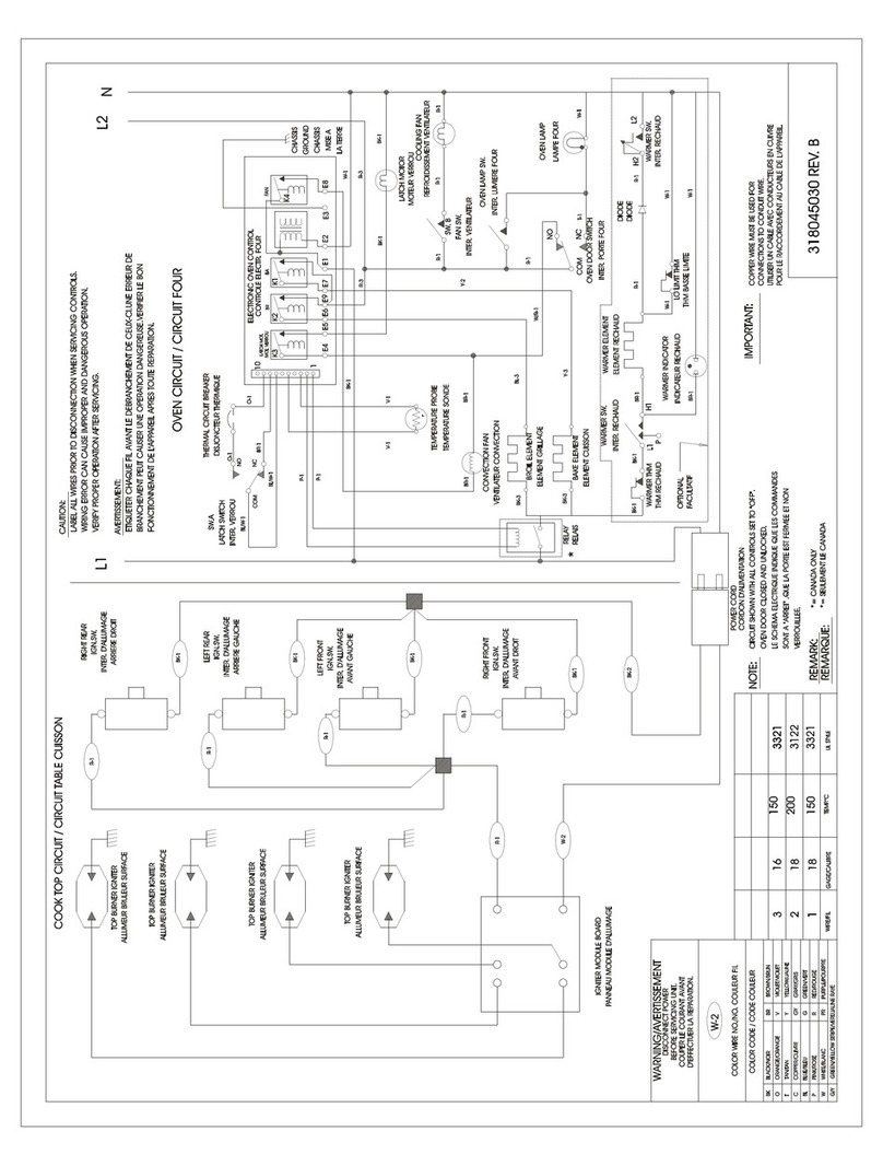
Frigidaire FCS388WHCB Wiring diagram
Clatronic
Clatronic EKP 3788 E instruction manual

Stove Guard
Stove Guard Guardian COOKTOP Installation & operating manual
Fisher & Paykel
Fisher & Paykel CG365DW Series user guide
Hupfer
Hupfer WHP Series operating instructions

Jenn-Air
Jenn-Air Pro-Style JGS8860BDP Use & care guide
