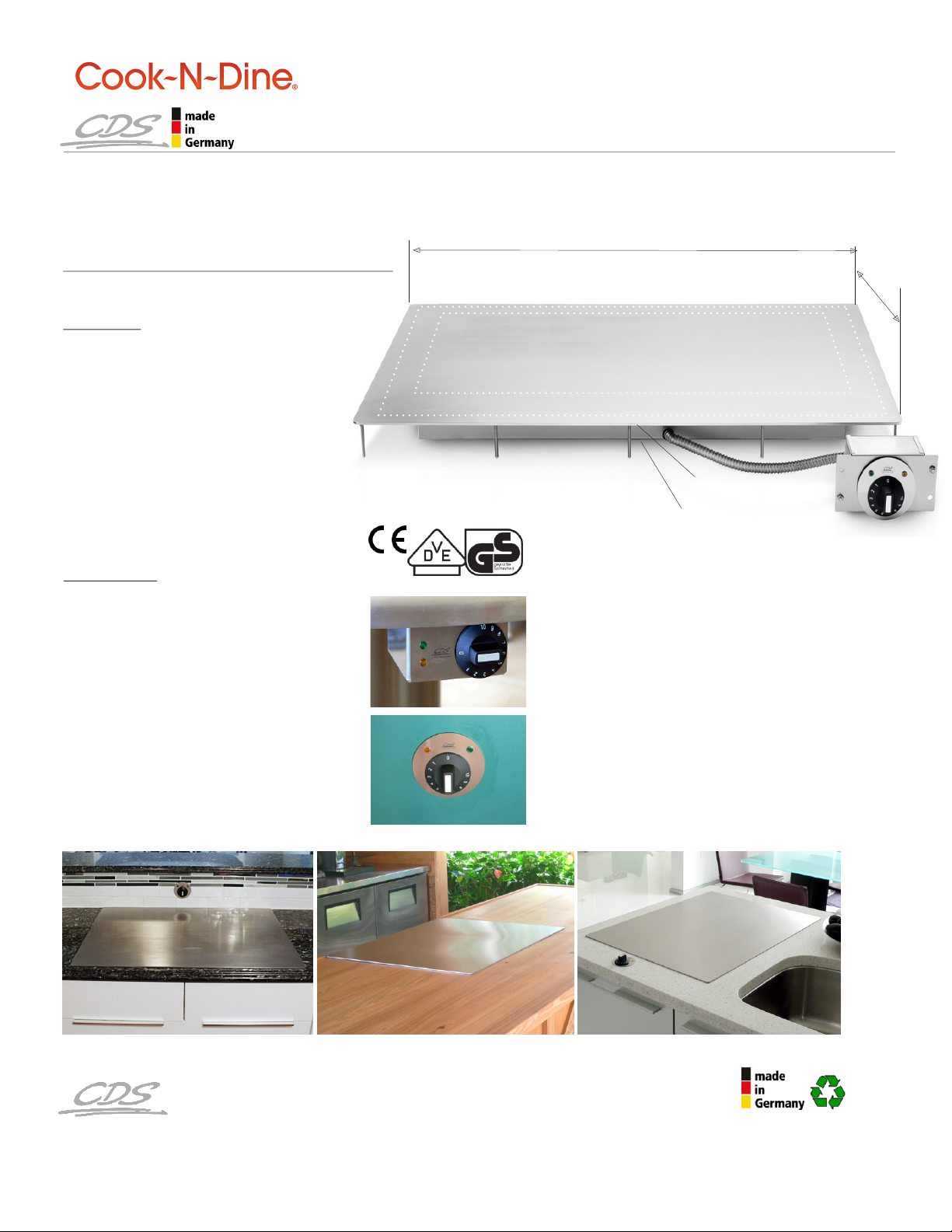
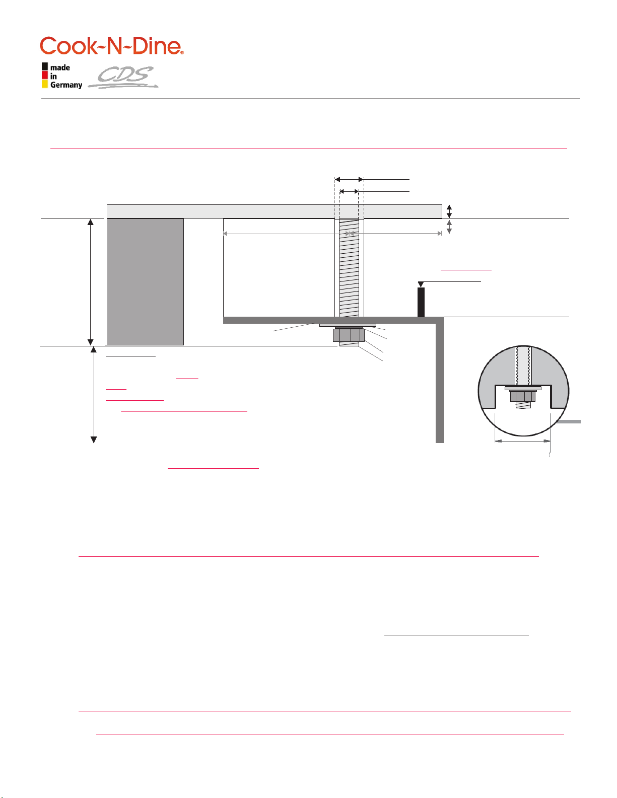
CDS Cook-N-Dine MO-80 User manual

BUILT-IN TEPPAN
model # MO-80
1
2
3
4
5
6
SOLID 304 STAINLESS STEEL TOP
CONTROL BOX “A” for open mount + outdoors
CONTROL BOX “B” for concealed mounting
FLEXIBLE CONDUIT
SEALED HEATING ELEMENT ENCLOSURE
STAINLESS STEEL MOUNTING BOLTS 1-3/4”
stainless steel washers & nuts included
10 FT. POWER CORD (3 m) included
COOKING GUIDE, included
8
9
CND TEPPANYAKI GRILL COOK TOP SPECIFICATIONS
Size: L 31-1/2” x W 23-5/8” (depth) |80 cm x 60 cm
!!! IMPORTANT: WILL NOT FIT ABOVE
STANDARD 24” DEEP* CABINETS !!!
(front-to-back facing long side)
Total cooking approx. 685 sq/in incl. warming
INDOOR + OUTDOOR USE | IPX4 RATED
Material: Professional Food Grade Best Alloy
German Stainless Steel type 304 (V2A)
5/32” thick (4 mm) cold pressed, hand-
welded. Built-to-last. Silk-brushed finish.
Power:
Electric:
1800 Watt | 1.8 kWh on high
120V | 50-60 Hz | 20 AMP
ProStyle: 2250 Watt | 240V | 10 AMP
Ship weight: 60 lbs | ship size 37” x 31” x 7”
Ship weight: 25 kg | ship size 93 x 74 x 13 cm
Analog temperature control:
1-10 dial | 2 indicator lights | thermostat
Contact Heat: 130ºF to 450ºF (55º-230ºC)
5 Year Limited Warranty.
Electrical + electronic parts:
1 year limited manufacturers’parts + labor.
VDE issued CE/ GS Safety Approval.
Electrical + Electronic
Components: UL approved.
OPTIONS:
- control box “B” for interior mount (default)
- control box ”A” for undermount + outdoors
1
4
2
3
6
6
6
5
3
L 31-1/2” | 80 cm
HOT cooking center
W 23-5/8”
~
1” ~3.5” warming
cool
The manufacturer reserves the right to update, change, alter or discontinue any model at any time without further notice.
2
“A” box
“B” box front plate
3
SINCE 1887 - OVER 125 YEARS OF INNOVATION & PRECISION MANUFACTURING
1-9/16”
built-in height
(40 mm)
ULTRA
SLIM !
PATENTED SHALLOW-DIP-TECHNOLOGY + CONTACT HEAT
Stainless steel production uses up to 80% recycled raw material
©2016 p&p | www.cookndine.com | All rights, errors and misprints reserved.

BUILT-IN TEPPAN
model # MO-80
INSTALL SHEET 1 of 2
©2016 p&p | www.cookndine.com | All rights, errors and misprints reserved.
23-5/8 inch
600 mm
MINIMUM CUTOUT
29-1/8 in | 740 mm
31-1/2 inch | 800 mm
1-3/4 inch
45 mm
9 ft
power
cord
MINIMUM
CUTOUT
21-1/4 in
540 mm
conduit length
~19.5” | ~500 mm
Electrical Rating: 120V |1800 Watt |15 AMP | 50-60 Hz >> REQUIRES 20 AMP ELECTRICAL BREAKER <<
1.8 kWh on high (alt. 240V/1800 Watt, 8 AMP or ProStyle 2250W-240V, 10 AMP)
8ALWAYS Check control box label for correct voltage BEFORE plugging in!
Bolts are 1-3/4 inch (45 mm) long; bolt diameter is 13/64ӯ (5 mm) 8drill 5/16ӯ (8 mm)
8 The Control Box MUST be firmly fastened to a NON-MOVING surface. Conduit + power cord to be secured.
8 CAUTION: DO NOT SNAP, PULL or TWIST THE CONDUIT DURING INSTALLATION ! ! !
Warranty becomes void if capillary tube (thermostat) inside the conduit is damaged during installation.
1.
2.
4.
Mark bolt holes, drill 5/16 inch | 8 mm olts will fit holes loosely.
Clean underside edges of unit with rubbing alcohol or similar.
3. Slide cook top into place. Do not apply excessive force. Unit needs to slide in without any resistance. Press
down evenly to compress Silicone. Secure ALL* BOLTS with supplied nuts and washers from underneath. Find all
nuts, washers and the extension key for “B” control in a small plastic bag inside the pouch.
!!! IMPORTANT: Tighten nuts with hand tool only. Do not use any power tools!!! *otherwise warranty becomes void.
Mark, drill and fasten the control box into place
Connect the power cord VERY FIRMLY to the rear of the control box. IMPORTANT: Check label and outlet for
correct voltage!!! Now connect the electrical 3-prong plug (other end) to a properly grounded power outlet.
ØØ - b Clean counter surface thoroughly!!!
Apply thin bead of Silicone Sealant around the edges of the underside of the unit. Do not leave any gaps.
This protects from potential moisture intrusion, especially when installed outside without overhead weather cover.
!!! IMPORTANT: MAKE SURE TO PREVENT SILICONE FROM GETTING INTO THE BOLT HOLES !!!
8REFER TO SEPARATE INSTALL SHEET FOR “B” CONTROL
Optional: seal the round metal plate with Silicone to prevent potential moisture intrusion.
!!! IMPORTANT: DO NOT DRILL NOR CUT ANY HOLES BEFORE UNIT IS PHYSICALLY PRESENT !!!
! ! ! DO NOT CUT OFF THE BOLTS ! ! ! DO NOT OPEN CONTROL BOX OR WARRANTY EXPIRES ! ! !
SPACE
REQUIREMENT
6 INCH H
10 CM H
OVERALL
BUILT IN
HEIGHT

BUILT-IN TEPPAN
INSTALLATION DETAIL
PAGE 2 of 3
Bolts/studs are 1-3/4 inch (45 mm) long; bolt/stud diameter is 3/16” (5 mm) 8drill 5/16” (8 mm) !!!Ø Ø
VERY IMPORTANT:
DO NOT CUT OR DRILL BEFORE UNIT IS PHYSICALLY PRESENT. DO NOT CUT OFF THE BOLTS/STUDS8 7
8 CAUTION: DO NOT SNAP, PULL or TWIST THE FLEXIBLE CONDUIT DURING INSTALLATION ! ! !
Warranty becomes void if capillary tube inside the conduit (thermostat) is damaged during installation.
CONTROL BOX MUST BE FIRMLY FASTENED TO A NON-MOVING SURFACE.
COUNTER TOP
COUNTER TOP
HEATING
ELEMENT
ENCLOSURE
CUTOUT
TEPPANYAKI COOK TOP COOK-TOP
8 MM | 5/16” REQUIRED HOLE DIAMETER
5 MM | 3/16” BOLT DIAMETER
45 MM
1.8 INCH
STUD
LENGTH
WASHER
LOCK WASHER
NUT
STUD
ANGLE
BRACKETS
PRE-PUNCHED 304
35” x 25/32” x 1-3/16” | 30 x 20 mm
(MO-80 + MO-61 only; order separately)
COUNTER SINK
nuts if necessary
8 7
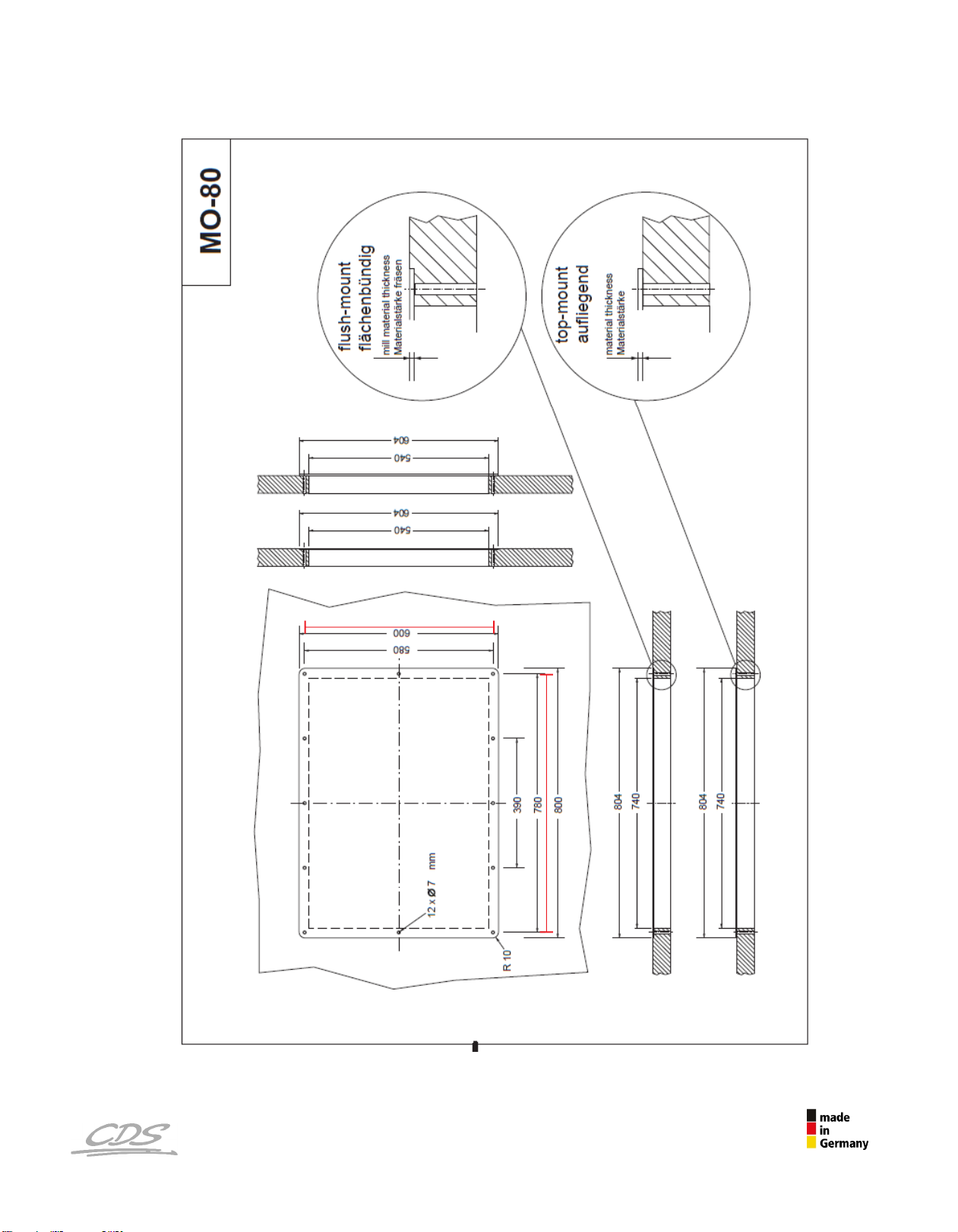
MO-80: Absolute minimum 6 inches from counter edge to edge of cook top are strongly advised.
! Make sure to HAVE THE UNIT and ALL install sheets ON SITE ahead of time for counter top templating !
ATTENTION !!! MUST READ !!! INSTALLATION INTO STONE/GRANITE COUNTER TOPS
Please be reminded that the CND stainless steel teppanyaki grill surface will flex slightly when switched on thus
developing a shallow dip in the cooking center. This motion is intended and is counteracted by the secured
studs, which hold the unit in place. Talk to your supplier and installer ahead of time. You must provide them
with a full set of install sheet documentation at that time. An experienced stone professional will be able to
advise on all aspects to watch out for, e.g. on how much counter-top (“meat”) is necessary at the narrowest point
for the particular stone of choice to accommodate a Cook-N-Dine built-in teppanyaki appliance properly.
IMPORTANT NOTE: COUNTER TOP THICKNESS OF ~1.5 IN (40 mm) IS MANUFACTURER ADVISED
UNLESS MATERIAL HAS BEEN RE-INFORCED BY MEANS OF RODDING OR COMPARABLE.
RODDING is a professional business practice to strengthen porous, fissured or “brittle” Natural Stone/Granite.
Narrow areas of material are reinforced on the underside
This will support and strengthen those areas and is intended to prevent possible damage.
CND offers 304 stainless steel custom-made 12 gauge pre-punched angle brackets (order separately) which
can be installed along the full length of the cutout (both long sides). The unit is then fastened through the
brackets’ pre-punched holes (see above). Stress applied to the counter material during operation should thus be
evenly distributed. VERY IMPORTANT: The use of brackets cannot guarantee the prevention of damage.
Everything strictly depends on the natural properties of the counter top material. Therefore, Cook-N-Dine can-
not be held responsible for any type of damage to stone counter tops due to installation/operation of CND units.
surrounding large cutouts (e.g. sinks, cook tops)
10 mm
3/8”
20 mm
3/4”
3-4 MM material strength
Optional:
Route metal thickness
for perfect flush installation
IMPORTANT:
WHEN INSERTING THE UNIT,
TIGHTEN THE NUTS WITH A HAND WRENCH.
DO NOT USE FORCE!!! NO POWER TOOLS!!!
THE STUDS MUST SLIDE
INTO THEIR DESIGNATED
HOLES EASILY AND
! ! ! WITHOUT ANY RESISTENCE ! ! !
RE-TIGHTEN AFTER A COUPLE OF USES. NOTE: DRAWINGS ARE NOT TO SCALE.
©2016 p&p | www.cookndine.com | All rights, errors and misprints reserved.
RODDING:
inserted epoxied metal rod
to re-inforce stone counter
(ref. OFFICIAL MARBLE
INSTITUTE OF AMERICA INFO)
4 inch | 10 cm
CLEARANCE

Hole
for fastening screws
Hole for
fastening
screws
Stem for
dial knob
Control
Light
Sockets
0
dial knob
Hollow Stem
Extension
DIRECTIONS:
1. Remove packaging and carefully pull off the DIAL KNOB ONLY while holding on to the round plate. Do not use force or tools!
2. Now separate the round steel plate from Control Light Sockets by carefully wiggling it away WITH the yellow and green light plastic caps
Hold one with two fingers and gently pull plate away; repeat with other. Yellow and green PLASTIC CAPS STAY IN PLACE in the plate.)
3. Mark all necessary holes utilizing the provided template below. Drill required holes and gently thread light sockets through their
designated openings. DO NOT SNAP THE PRONGS! Now fasten the box to interior of cabinet wall or underside of counter top.
4. Gently pull light sockets out a little bit and re-connect with plastic caps in the metal plate; affix plate with two small flathead screws, or
silicone into place.
5. Connect the hollow extension to stem if needed (packed with nuts + washers). Slide dial knob onto stem (match flat side of stem
with flat side of female receptacle at back of knob). Do not use force. The “0” has to align centered below the CDS logo.
CAUTION: DO NOT TWIST OR SNAP DELICATE WHITE WIRING OF INDICATOR LIGHTS.
BUILT-IN TEPPAN
TYPE “B” CONTROL BOX
CONCEALED MOUNT
4” (102 mm)
3” (76 mm)
2-3/8”
(60 mm)
5-3/8” (137 mm)
Holes for screws
to attach
plate
Hole
for
stem
Control/Indicator Light
Plastic Caps
11/16"
11/16"
9/32" 9/32"
1 17/32"
1 17/32"
1 13/16 in
4 7/8"
5 3/8"
ø 3/8”
10 mm
ø
6 mm
7/32”
ø 7/32”
6 mm
ø 9/64”
3.6 mm
ø 9/64”
3.6 mm
ø 9/64”
3.6 mm
ø 9/64”
3.6 mm
ø 5/8”
16 mm
8 CAUTION: DO NOT SNAP, PULL or TWIST THE CONDUIT DURING INSTALLATION ! ! !
Warranty will expire if capillary tube inside the conduit is damaged during installation.
Control box must be firmly fastened to a non-moving surface.
8 VERY IMPORTANT NOTE: Do not open the control box or warranty expires!
IMPORTANT: To use as 1:1 template
set “page scaling” to “none” when printing
Stainless
Steel Cover Plate
3-1/8“ dia (80 mm)
cabinet
wall
interior
cabinet
space exterior
YELLOW
GREEN
7 mm
39 mm
18 mm
18 mm
46 mm
39 mm
7 mm
124 mm
8137 mm - PLEASE MEASURE ACROSS TO MAKE SURE TEMPLATE IS 1:1
Prongs prevent
light sockets from
slipping into box only
©2016 p&p | www.cookndine.com | All rights, errors and misprints reserved.

SINCE 1887 - OVER 125 YEARS OF INNOVATION & PRECISION MANUFACTURING
©2016 p&p | www.cookndine.com | All rights, errors and misprints reserved.
bolt spacing
30.709in
bolt spacing
22.835in
Popular Cooktop manuals by other brands

AIRLUX
AIRLUX ATI322BK Instructions of use and maintenance

Teka
Teka IZS 96600 MSP user manual

NEFF
NEFF T28V56N0 Operating, installation and caring instructions

Cosmo
Cosmo COS-DIC304 Installation & user manual

Fisher & Paykel
Fisher & Paykel CE365DBX1 Product dimensions

Fisher & Paykel
Fisher & Paykel MINIMAL CID834DTB4 installation guide