Craden DP6 User manual

1
1.0 DP6 & DP7 DOCUMENT PRINTERS - FUNCTIONAL SPECIFICATIONS
1.1 PRINT CHARACTERISTICS
Print Method Impact with automatic thickness compensation
DP6: 9 wire dot matrix DP7: 24 wire dot matrix
Print Line Width 8.0” (203 mm)
Character Spacing 5, 6, 8.5, 10, 12, 17, 20 and 24 characters/inch
Font 96 char. ASCII, international character support
Print Speed
(chars/second)
DP6 DP6 DP7 DP7
Chars/inch 10 12 10 12
Draft 165 200
Normal 125 150 150 180
Correspondence 32 37 75 90
Dot Graphics
(dots/inch)
DP6: 60, 120, 240 horizontal; 72, 144 vertical
DP7: 60,120,180, 360 horizontal; 72, 180 vertical
Feed Speed 50 msec. single line feed at 5 or 6 lines/inch
12 inches/second (305 mm/sec) slew speed
Feed Accuracy +/- 0.6%
1.2 FORMS CHARACTERISTICS
Media Single sheets, passbooks, 6 part multipart forms and
envelopes.
Document Width 2.5” (64 mm) to 9.5” (241 mm)
Document Length 2.5” (64 mm) minimum, no maximum
Document Thickness 0.0035” (0.09 mm) to 0.062” (1.57 mm)
Non-printable Areas DP6 DP7
Top of form 0.25”(6.4mm) 0.16”(4.1mm)
Above horiz. fold 0.25”(6.4mm) 0.38”(9.7mm
Below horiz. fold 0.31”(7.9mm) 0.27”(6.9mm)
Bottom of form 0.40”(10.2mm) 0.45”(11.4mm)
Vertical fold/edge 0.25”(6.4mm) 0.25”(6.4mm)
1.3 RIBBON
Cartridge Endless loop ribbon with internal reinking
DP6: NEC P2200 compatible
DP7: Panasonic KX-P155 compatible

2
1.4 INTERFACE
Standard Serial RS-232, DP6: 1200-9600 baud, 4KB buffer
DP7: 2400-19200 baud, 11KB buffer
Optional RS-232 dual ports or PC parallel port
Command Sets IBM Proprinter/4722, Unisys and Craden
Protocols DTR, Xon/Xoff and Block
Power Input 100-130 or 200-260 VAC, 50-60 Hz, 50 W max.
1.5 PHYSICAL CHARACTERISTICS
Dimensions Width: 14.1” (357mm) Height: 6.3” (160 mm)
Depth: 10.8” (275 mm) operating, 7.8” (197 mm) standby
Weight 18.3 pounds (8.3 kg) + 3.5 pounds (1.6 kg) packing
1.6 ENVIRONMENTAL & STANDARDS
Operating
Storage
10 to 40C, 10 to 90% humidity
-30 to 70C, 5 to 95% humidity
Standards IEC 950, UL 1950, UL File E91899
FCC 20780 Class A certified, Canadian UL Listed

3
2.0 INSTALLATION
2.1 NORMAL INSTALLATION PROCEDURE
1. Read this section and 3.1 to 3.6 on Operation and Configuration.
2. Remove the cabinet lid and cut the shipping strap that fastens the carriage to the rail on the metal box.
Save the packing material.
3. Install the ribbon cartridge (See 3.3).
4. Check that the label on the printer rear correctly indicates the input supply voltage. (Either 115 VAC for
100-130 VAC input or 230 VAC for 200-260 VAC). If it is incorrect, see Changing Supply Voltage in 2.3.
CAUTION: CONNECTION OF A PRINTER WIRED FOR 115 VAC TO A 230 VAC INPUT CAN
PERMANENTLY DAMAGE THE PRINTER!
5. Check that the power switch on the printer rear is off ("0" side depressed). Connect the line cord to the
printer and then to an electrical outlet. If a suitable line cord was not supplied with the printer, procure an
IEC HAR (harmonized) line cord that has an IEC 320-C13 style connector and the appropriate HAR plug
for your country.
6. Connect and fasten the interface cable to the rear panel connector. (See 3.13.3 for cabling information).
7. Documents longer than 8" will feed out the printer rear. Insure that space is available for the longest
document to be fed.
8. Turn on the power switch located on the rear of the printer. READY should be displayed.
9. Configure the printer by the procedure in 3.6. Default settings are:
LINES/INCH = 6 PROTOCOL = DTR
CHARS/INCH = 10 BAUD RATE = 9600
CHARS = SCRIPT WORD LENGTH = 8
PRINT = NORMAL PARITY = NONE
QUIET MODE = N STOP BITS = 1
DOCUMENT INSERT TOP EDGE INPUT BUFFER MULTIPLE LINE INSERT WITH 1 SEC
PAUSE EMULATION MODE C
BEGIN PRINTING IMMEDIATELY RETURN ON FEED Y
LINE#1 =. 250 IN
In printers with the automatic alignment feature:
SKEW DETECTION CORRECT SKEW
SKEW DETECTION ALLOWED = .050
IF FORM SKEWED ENTER/EJECT KEYS
IF NARROW FORM PROCEED
Common variations are EMULATION MODE I for IBM Proprinter emulation and PROTOCOL = XON/XOF
for software that does not use DTR hardware handshaking. Function 94 settings are factory selected for a
specific printer mechanism and should not usually be changed.
10. Perform a local print test using 95 FUNCT. (See 3.9)
11. If the host is unable to print correctly, check that the Communication Parameters selected under 93
FUNCT match the host parameters and review all Printer Parameters selected under 92 FUNCT.

4
2.2 RESHIPMENT
If possible, retain the original packing material for reshipment. In any event the following precautions must
be observed:
1. Fasten the carriage with a cable tie, string or wire passing around the top of the carriage plate and through
the hole in the front of the guide rail. Insure that the carriage can't move horizontally or vertically.
2. If the original packing material is not used, insure that the cabinet lid will not move during shipment and
that the unit has sufficient protective padding on all sides.
2.3 CHANGING SUPPLY VOLTAGE
The printer can be set to operate with either 115 VAC or 230 VAC input. It will operate from 50 or 60 Hz at
either setting. The label on the back indicates the current setting. To change the voltage setting:
CAUTION: THIS CHANGE MUST BE PERFORMED BY TRAINED SERVICE PERSONNEL
1. Disconnect the line cord from the printer.
2. Remove the screw on the right end of the line cord receptacle and the screw to the left of the power switch.
Slide the power input assembly out of the printer rear.
3. Disconnect the internal power cable from the power input assembly.
4. Use a small blade to depress the locking tab on the side of the green/yellow wire contact and slide the
contact out of the connector. Use the blade to pry the plastic key out of the cable connector.
5. Insert the green/yellow wire contact into the connector position where the key had been and insure that it
locks in place. Insert the key into the connector position where the green/yellow wire had been.
6. Reconnect the internal connector to the power input assembly.
7. CHECK THE CONNECTOR TO THIS CHART. THIS IS IMPORTANT!
Position 1 is the pin closest to the power switch.
Position: 1 2 3 4 5 6 7 8
115 VAC: Brown Blue Grn/Yel Wht/Brn Key Wht/Blue
230 VAC: Wht/Blue Grn/Yel Wht/Brn Key Blue Brown
8. Use a meter to insure there is less than 0.1 ohm resistance from the center blade of the line cord
receptacle and the printer baseplate.
9. Slide the power input assembly back into the printer and fasten it.
10. Replace the fuse and fuse holder with the type indicated on the label on the back corresponding to the new
input voltage.
11. Modify the label on the back to indicate the new supply voltage.

5
3.0 OPERATION
3.1 AUTOMATIC DOCUMENT INSERTION
Insertion procedures may be configured to satisfy varied applications. (See Printer
Parameters in 3.6.1). This description first explains a basic insertion sequence and then
describes variations.
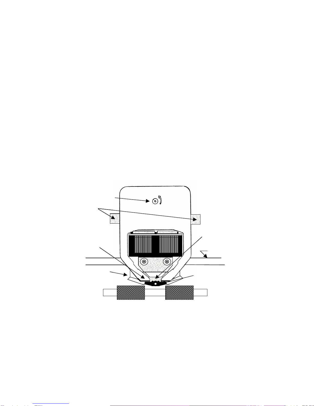
1. Place the document under the clear plastic guide and gently push the left edge of the
document against the edge of the document guide.
2. Slide the document forward until it contacts the feed rollers which will automatically
move the document to the first printable line.
3. Printing can now commence. After printing is complete the document may be ejected.
Step 2 may be configured so that the rollers do not activate for a few seconds or until the
A key is pressed. This allows more time to insert cumbersome documents or to train
new operators.
Printers with the auto alignment feature should be configured for no delay. Documents
should be inserted toward the left edge guide and rollers, then quickly released to allow
them to automatically align. Auto alignment may be disabled for an individual document by
pressing the FUNCT key before insertion. See 3.6.5 to configure auto alignment.
Step 2 may be configured to move the document down to the last (bottommost) printable
line.
Step 3 may be configured to delay printing until the ENTER key is pressed. This allows
the operator to insure that the document has inserted correctly. If not, it may be EJECTed
and reinserted.
3.2 SEMI-AUTOMATIC DOCUMENT INSERTION
If delay printing until the ENTER key is pressed has been configured, the document can be positioned to
begin printing at a specific place:
1. Proceed with steps 1 and 2 of the automatic insertion procedure.
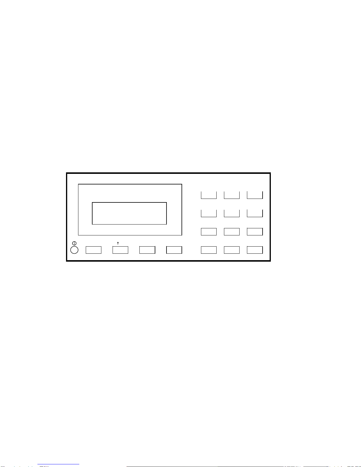
2. Use the A and B keys to align the center of the desired print line with the front edge of the metal guide
above the document.
3. Press the ENTER key. The desired print line will be automatically positioned in front of the printhead and
printing can now begin.
4. After printing is complete the document may be ejected.
When Configuration 12 is selected in 94 FUNCT, pressing ENTER before document insertion allows keypad
entry of the number of lines to be fed before printing begins.
3.3 RIBBON CARTRIDGE LOADING/REPLACEMENT
The DP6 cartridge (Part# 99059) is compatible with the NEC P2200 cartridge. Its drive knob is on the right
side of the cartridge. The DP7 cartridge (Part # 99073) is compatible with the Panasonic KX-P155. Its drive
knob is in the center of the cartridge. The useful life of cartridges from various suppliers may vary greatly and
some may be too heavily reinked for document printing applications. The reinker in some DP7 cartridges
must be manually engaged by removing a clip or pressing a spring when printing becomes light. Do not
engage the reinker until printing becomes light or else printing will become too dark.

6
3.3.1 DP6 Ribbon Cartridge Loading/Replacement
To replace a DP6 ribbon cartridge:
1. Remove the lid. If the printer has just finished more than 3 minutes of continuous printing, the printhead
fins may be hot to the touch. Avoid contact with the fins.
2. Press the A and B keys simultaneously to position the printhead nose just to the right of the leftmost
rubber roller segment.
3. Release the old cartridge from the carriage by pulling the release bar on top of the cartridge forward. Lift
the carriage shaft and remove the old cartridge.
4. Rotate the ribbon drive knob until the slot on its bottom side lines up with the ribbon drive tab on the
carriage. Pull a small loop of ribbon from the nose of the cartridge.
5. Lift the carriage shaft with a little finger. Insert the ribbon loop between the bottom of the printhead nose
and slotted plastic ribbon shield and then push the cartridge against the carriage until it snaps into place.
6. Insure that the ribbon is located between the printhead nose and the ribbon shield and the shield is seated
with the notched side toward the rear of the printer. If the ribbon is caught on the front of the printhead
nose use a pen point to push it into place. Rotate the knob on the cartridge clockwise and check that the
ribbon moves correctly.
Ribbon Shield
Ribbon Drive Knob
Release Bar
Carriage Shaft
Printhead Fins
Gap Adjust Screws (2)Printhead Attach Screws (2)
Printhead Nose
Leftmost Roller
DP6 RIBBON CARTRIDGE LOADING

7
3.3.2 DP7 Ribbon Cartridge Loading/Replacement
To replace a DP7 ribbon cartridge:
1. If the new cartridge has a plastic ribbon shield attached, remove it.
2. Pull about a 1/2" loop of ribbon from the new cartridge.
3. Remove the lid. If several minutes of continuous printing have just been finished, the printhead and
carriage may be hot to the touch. Avoid contact with those parts.
4. Press the A and B keys simultaneously to position the printhead nose between two drive roller
segments.
5. Lift the carriage shaft with a little finger. Remove the old cartridge by pressing the side clips while pulling
the old cartridge forward.
6. Push the metal ribbon shield downward. Guide the new cartridge's ribbon loop around the pivoting slider
and under the printhead nose.
7. Locate the cartridge tips behind the pivoting slider.
8. Move the cartridge toward the carriage and rotate the cartridge knob counter-clockwise until the cartridge
seats on the carriage plate.
9. Insure that the ribbon lies flat against the printhead nose and that both metal side clips lock onto the
cartridge tabs.
3.4 KEYPAD OPERATION
EJECT: ejects an inserted document if the print buffer is empty.
Drive Knob
Side Clips
Cartridge Tip
Ribbon Shield
Printhead Nose
Carriage Shaft
Pivoting Slider
DP7 RIBBON CARTRIDGE LOADING

8
A: moves a document up 1/60" with each depression. If held depressed, the document will slowly
move into the printer. Also initiates document insertion if the printer is configured for key rather
than automatic insertion. (See 3.6.1)
B: moves a document down 1/60" with each depression. If held depressed, the document will slowly
move out of the printer .
FUNCT: enters previously keyed digits as a function code. All function codes beginning with 9 are reserved
for internal printer operations. All other function codes are transmitted to the host system and
their usage is defined by the host. On printers with the auto alignment feature, pressing FUNCT
before document insertion will disable auto alignment for an individual document. See 3.6.5 to
configure auto alignment.
CLEAR: erases any previously keyed digits before they are transmitted to the host by the FUNCT or
ENTER keys.
ENTER: transmits previously keyed digits to the host system. All responses are defined by the host. This
key also initiates document printing if the printer is configured to delay printing until the ENTER
key is pressed (See 3.6.1).
0 to 9: enter digits to be transmitted to the host by the FUNCT or ENTER keys. Key depressions appear
on the lower display line.
KEYPAD & DISPLAY
PANEL
3.5 DISPLAY
OPERATION
The display
consists of 2 lines
of 16 characters
each and is used
to display messages both from the printer and the host system. There is a contrast knob to the left of the
EJECT key that should be adjusted for maximum legibility depending on the display viewing angle. When the
printer is turned on, "READY" will be displayed.
READY
1
2
FUNCT CLEAR ENTEREJECT
3
4
5
6
7
8
9
0
B
A

9
3.6 CONFIGURATION
The printer may be completely configured from the keypad with all parameters saved in a non-volatile
memory. There are 4 configuration function codes:
Configuration Category Press
Printer Parameters 9 2 then FUNCT
Communication Parameters 9 3 then FUNCT
Service Parameters 9 4 then FUNCT
Override Parameters 9 9 then FUNCT
After accessing a category, each parameter will be displayed. Press A to display the next choice for the
parameter or press ENTER to display the next parameter. If the display does not change when A is
pressed, the keypad is locked. See 3.6.4 to unlock the keypad.
3.6.1 Printer Parameters
Press 9 2 then FUNCT to display the following parameters or press 9 0 0 then FUNCT to print them on a
previously inserted document. Changes may be made as described above. Before proceeding, see 3.1-3.2
and select the insertion sequence which best fits your application.
DISPLAY REMARKS
LINES/INCH = 5 or 6 Select 5 or 6 lines per inch vertical spacing
CHARS/INCH = 10, 12 or 17 Select 10, 12 or 17 characters per inch horizontal spacing.
CHARS = BLOCK or SCRIPT Select BLOCK or SCRIPT lower case characters in NORMAL mode
(DP6 only).
PRINT = NORMAL, CQ or
DRAFT Select NORMAL, correspondence quality CQ or high speed DRAFT
(DP6 only) print. Do not use DRAFT on thick forms or passbooks.
QUIET MODE = Y or N Select Y for reduced noise on thin documents. Select N for darker print
on thick documents.
DOCUMENT INSERT = TOP
or BOTTOM EDGE Select insertion to the TOP EDGE or the BOTTOM EDGE of the
document.
DOCUMENT INSERT WITH
X SEC PAUSE or WITH A
KEY
Select automatic insertion 0, 1 or 2 seconds after a placing a
document in the input tray or delay insertion until A is pressed to allow
more time for aligning documents.
BEGIN PRINTING
IMMEDIATELY or
AFTER ENTER KEY
Select to begin printing IMMEDIATELY after the document insertion or
delay printing until ENTER is pressed to verify proper alignment.
LINE # 1 = .XXX Select the distance, between -0.80” and 0.80”, from the document top
edge to the center of the first print line. Select 0.25” unless needing
software compatibility with another printer.
See 3.6.5 for automatic alignment parameters that appear on the Printer Parameter menu.
NOTE: Most Printer Parameters may be configured by the host system via the HT or other commands. This
allows for dynamic reconfiguration on a document by document or line by line basis.

10
3.6.2 Communication Parameters
Press 9 3 then FUNCT to display the following Communication Parameters or press 9 0 0 then FUNCT to
print them on a previously inserted document. Changes may be made as described in 3.6.
DISPLAY REMARKS
INTERFACE PROTOCOL =
BLOCK, DTR, XON/XOF or
PARALLEL INTERFACE
Select the protocol which matches your system configuration (See
3.13). Select PARALLEL if the parallel interface option is installed
& skip the next 4 items.
BAUD RATE = XXXX Select 1200 (DP6 only), 2400, 4800, 9600 or 19200 (DP7 only)
baud.
WORD LENGTH = 7 or 8 Select 7 or 8 bits/word.
PARITY = XXXX Select parity bit as EVEN, ODD or NONE.
STOP BITS = 1 or 2 Select 1 or 2 stop bits.
INPUT BUFFER SINGLE LINE or
MULTIPLE LINE Select a SINGLE LINE or a MULTIPLE LINE buffer of 3K (DP6)
or 11K (DP7).
EMULATION MODE =
C, I, EF4565 or
EF4600/EFP95
Select C to enable commands used with previous versions of this
printer. Other selections enable commands compatible with
popular PC based financial printers.
AUTO CARRIAGE RETURN ON
FEED = Y or N or
N
Select Y unless compatibility with software written for another
printer is needed.
DUAL PORT = Y or N Select Y if the dual port option is installed to allow printer sharing
between two hosts. Either DTR or XON/XOF protocol must be
selected.
PAPER OUT = NO DOC or
NEVER Select NO DOC if the parallel interface is to indicate paper empty
whenever no document is in the printer or NEVER if it is never to
indicate paper empty.
SELECT = DOC PRES or
ALWAYS Select DOC PRES if the parallel interface is to indicate off-line
whenever no document is in the printer or ALWAYS to always
indicate on-line.

11
3.6.3 Service Parameters
Press 9 4 then FUNCT to display the following Service Parameters. These parameters are factory selected
specifically for each printer mechanism and recorded on the label next to the display inside the printer. They
do not usually need to be modified by the user.
CAUTION: CHANGE OF THESE PARAMETERS BY UNTRAINED PERSONNEL MAY RESULT IN
INCORRECT PRINTER OPERATION.
DISPLAY REMARKS
TOP OFFSET = XX Adjusts the uppermost print line location. Smaller values print
closer to the top document edge.
INDEX OFFSET = XX Adjusts the distance moved when semi-automatic positioning is
used. Larger values move the print line up the document.
LEFT OFFSET = XX Adjusts the carriage home location during document insertion.
Larger values move the carriage to the left.
LEFT MARGIN = XX Adjusts the first column print position. Larger values move printing
to the right.
CAR. ALIGN = XX Positions lines printed right to left so they align with lines printed left
to right. Larger values move those lines to the left.
FORWARD COMPENSATION
= XX Adjusts distances moved down the document. Larger values
increase the distance moved between the topmost and bottommost
line.
REVERSE COMPENSATION
= XX Adjusts distances moved up the document. Larger values increase
the distance moved between the bottommost and topmost line.
EJECT HOLD OFFSET = XX Adjusts how much of the document is held in the feed rollers after it
is ejected. Lower values hold less of the document.
CONFIGURATION = XX Selects custom interface options. Select 00 unless indicated
otherwise on the Parameter label or incorrect operation may occur.
GATE OFFSET = XX Adjusts gate height. Larger values raise gate. (DP7 with Automatic
Alignment feature only)
NORMAL DARKNESS = 0 to
10 Adjusts darkness at normal print speed. Lower values reduce
darkness and increase ribbon life. Select the lowest value that
provides suitable legibility on thick forms (DP7 only).
CQ DARKNESS = 0 to 10 Adjusts CQ print darkness (DP7 only).

12
3.6.4 Override Parameters
Press 9 9 then FUNCT to display the following Override Parameters. Changes should be made only by
trained personnel.
DISPLAY REMARKS
LOCKED or UNLOCKED LOCKED allows parameters to be displayed but not changed.
UNLOCKED allows parameters to be changed by the A key.
COVER OVERRIDE OFF or
ON OFF requires the cabinet lid to be closed for printing to occur. ON
allows trained personnel to print with the lid removed. Replacing the lid
automatically sets the override OFF.
3.6.5 Automatic Alignment Parameters
The following printer parameters may be selected at the end of the Printer Parameter (9 2 FUNCT)
menu on printers with the automatic alignment feature:
DISPLAY REMARKS
SKEW DETECTION =
CORRECT SKEW, DETECT
SKEW, or IGNORE
select CORRECT SKEW to automatically align skewed documents,
DETECT SKEW to detect but not align skewed documents, or
IGNORE to disable both skew detection and correction.
SKEW DETECTION ALLOWED
= .030, .050, .080, .110 or .130 Select the maximum skew per 4 inches of document width. Treatment
of documents with excess skew is set by the next parameter.
IF FORM SKEWED =
ENTER/EJECT KEYS or
AUTOMATIC EJECT
If a document has excess skew, ENTER/ EJECT KEYS will continue
printing if ENTER is pressed or eject the document if EJECT is
pressed. AUTOMATIC EJECT will always eject a document with
excess skew
IF NARROW FORM =
PROCEED or ENTER/EJECT
KEYS
Documents less than 4.5 inches wide will be detected as skewed.
PROCEED will always accept the document, ENTER/EJECT KEYS will
continue printing if ENTER is pressed or eject the document if EJECT
is pressed.
3.7 DIAGNOSTICS
3.7.1 Power Up Diagnostics
Diagnostic routines are automatically executed during power-up. If a fault is detected, ROM TEST BAD
or RAM TEST BAD may be displayed. If a fault occurs, press A to advance to the next test. However,
the printer should not then be operated. If the problem is not a POWER FAILURE (see 3.10.1), contact
your Service Personnel or see 5.6 of the Technical Manual for troubleshooting.
3.7.2 Enhanced Diagnostics
Diagnostics may be executed by pressing 9 0 then FUNCT. If no faults exist, PROM REVISION XX,
ROM TEST OK and RAM TEST OK will be displayed. If a fault exists, "BAD" will be displayed instead of
"OK" until A is pressed to advance to the next test.
After RAM TEST XXX is displayed, SENSORS LFBC will be displayed. L is the left home carriage sensor; F
and B are the front and back document sensors and C is the cover open sensor. Any sensor that is covered
will have its corresponding indicator erased. Each sensor may be activated to check for proper operation.
Press A to conclude this test.

13
3.8 SELF TEST
A document may be test printed by pressing 9 1 FUNCT. SELF TEST is displayed until a document is
inserted. Then CHAR LENGTH = 30 is displayed. Press A to select CHAR LENGTH = 80. (30 characters
requires a document at least 3 1/2" wide, 80 characters requires 8 1/2".) Do not print across a vertical fold or
document edge. Press ENTER to print the top and bottom lines of the document and then eject it.
3.9 LOCAL PRINTING
In addition to Self Test function 91, it is possible to print several variable length lines without host commands.
Proceed as follows:
1. Insert a form manually or automatically and then press 9 5 FUNCT.
2. In response to CHAR LENGTH = 30, key in a two digit number of characters per line and then press
ENTER. Insure that printing will not occur across a fold or document edge.
3. In response to LINE COUNT = 01, key in a 2 digit number of lines.
4. Each time ENTER is pressed, that number of lines will be printed.
5. Press EJECT to eject the document and CLEAR to clear the display.
3.10 ERROR CONDITIONS
3.10.1 Power Failure
All Configuration Parameters are stored in a non-volatile memory. Power up diagnostics display POWER
FAILURE if an error is detected in that memory. It is now necessary to re-enter the parameters. Press
FUNCT to begin the prompting sequence. The factory set values for the Service Parameters are listed on
the label next to the display inside the printer.
3.10.2 Document Jam
In the unlikely event that a document becomes jammed in the printer, printing will stop and "DOCUMENT
JAM" will be displayed. The operator must clear the jam condition by moving the printhead left as far as
possible and removing the document from the printer.
3.10.3 Cover Open
If the printer lid is removed to replace a ribbon cartridge or clear a document jam, COVER OPEN is displayed
and printing is disabled. Printing will resume 3 seconds after the lid is replaced.
3.10.4 Page Overflow
If the printer is commanded to move past the last printable line on a document it will eject the document and
display PAGE OVERFLOW INSERT NEXT PAGE. Printing will resume when another document is inserted.
3.10.5 Carriage Fault
This message will be displayed if the carriage could not move to the left margin and is probably caused by a
jammed carriage, bad motor driver fuse or a bad left home sensor.

14
3.11 DP6 & DP7 PROGRAMMING
CAUTION: DURING PROGRAM DEVELOPMENT ALL PRINTING SHOULD BE DONE ON SINGLE
SHEET PAPER UNTIL PRINT FIELDS ARE CORRECTLY FORMATTED. PRINTING DIRECTLY ACROSS
THICK FOLDS AND DOCUMENT EDGES CAN DAMAGE THE PRINTHEAD.
The printer accepts two separate command sets, C and I, that are selectable either from the keypad using 9
3 FUNCT (see 3.6.2) or the interface. Mode C is compatible with previous versions of this printer while Mode
I is compatible with popular PC based printers. If Mode I is selected, the DP6 can use a IBM Proprinter driver
and the DP7 can use a IBM Proprinter X24 driver. Unique Mode C commands to communicate with the
keypad/display and request status can still be accessed in Mode I by preceding the Mode C command with a
ESC character.
3.11.1 Mode C Command Summary
Mode C recognizes the following ASCII control sequences:
ASCII Hex Command
STX 02 Start envelope data
ENQ 05 Status request
BEL 07 Load upper display immediate
* BS 08 Reverse line feed
HT 09 Configuration download
* LF 0A Line feed
* VT 0B Vertical tab feed
* FF 0C Eject document
* CR 0D Print buffer
SO 0E Begin expanded characters
SI 0F End expanded characters
DC1/DLE 11/10 Key buffer request
DC2 12 Line count request
DC3/ETB 13/17 Load upper display delayed
DC4 14 Master reset
EM 19 Document length request
SUB 1A Status request delayed
ESC SO 1B 0E Begin double height characters
ESC SI 1B 0F End double height characters
* ESC n 1B 3# Feed document up #/120 inches
ESC A 1B 41 Begin 60 dot/inch graphics
ESC B 1B 42 Begin 120 dot/inch graphics
ESC E 1B 45 Begin bold print
ESC F 1B 46 End bold print
* ESC J n 1B 4A Feed document up n/216 inches
ESC ] 1B 5D Reverse line feed
ESC ~ I 1B 7E 49 Select Mode I
FS 1C Load lower display immediate
GS 1D Load lower display delayed
RS n 1E n Skip n blank spaces in print line
US 1F Begin/End underscore
Commands prefixed with a * will not be executed until after an ENQ is received if the BLOCK protocol is
used. ENQs are not required if DTR or XON/XOF protocols are used.

15
3.11.2 Mode C Document Movement Commands
BS or ESC ] moves the document down one line, with line spacing keypad selected (see
3.6.1) or set by an HT command.
LF moves the document up one line, with line spacing keypad selected (see 3.6.1) or set by
an HT command.
VT n moves the document a variable number of lines or steps with n being a single byte, bit
coded as 01ULCCCC where:
U = 1 = Up feed U = 0 = Down feed
L = 1 = Line feed (1/6” or 1/5”) L = 0 = Step feed (1/60”)
CCCC = Line count or step count
ESC n moves the document up (CCCC)/120 inches where n is a single byte bit coded as
0011CCCC.
ESC J n moves the document up n/216 inches where n is a single binary coded byte.
FF ejects the document.
If any document movement command (BS, LF, VT, ESC n, ESC ], ESC J n or FF) has been preceded by any
printable ASCII characters, they will be printed before the movement command is executed.
3.11.3 Mode C Print Commands
CR prints all preceding printable ASCII characters. There is no document movement due to the
CR.
SO starts double width printing. All characters received after an SO and before an SI, CR or
feed command will be printed double width.
SI stops double width character printing.
ESC SO starts double height printing. All characters received after an ESC SO and before an ESC SI,
CR or feed command will be printed double height. Single height characters will be printed in
line with the top of double height characters if they are mixed in a print line.
ESC SI stops double height printing.
ESC E starts bold, double strike printing in 10 and 12 character/inch NORMAL print speed and
reduces print speed by 33% (DP6) or 50% (DP7).
ESC F stops bold printing.
RS n inserts n blank spaces into the print line and can be used to reduce the number of
characters transmitted when large blank spaces are to be printed. n is of the form
01NNNNNN where NNNNNN is the number of blanks to be inserted. RS A is 1 blank, RS z
is 58.
US enables or disables underscoring of printable characters. All characters received after a US
and before another US, CR or feed command will be printed with the character underscored.
STX
prints envelopes. It must be immediately followed by two bytes, X and Y, each bit coded as
01NNNNNN. NNNNNN/10 inches is the distance from the top edge of the envelope to the first
line of text for X and from the left edge of the envelope to the first column of text for Y.
Following X and Y are normal lines of text separated by
LF's and finally terminated by a FF
which causes printing and ejection.
DC4 clears all previously received data out of the buffer.

16
3.11.4 Mode C Display Commands
BEL immediately displays the following 16 characters on the upper line of the alphanumeric
display. The characters must not be control characters and there must be exactly 16
displayable characters.
FS loads the lower display line just like BEL loads the upper line.
DC3 or ETB operate identically to a BEL command but all previously received print and
document movement commands are executed before the upper line of the display is
loaded.
GS loads the lower display line just like DC3 loads the upper line.
3.11.5 Mode C Configuration Commands
HT changes the machine configuration and must be followed by 2 characters of the form
01PVHFCS and 01LEIBDQ where:
P = 1: Permanent configuration change.
0: Change just for one document
V = 1: 5 lines/inch vertical spacing
0: 6 lines/inch vertical spacing
H = 1: 12 characters/inch horizontal spacingif S=0
0: 10 characters/inch horizontal spacing if S=0
F = 1: Script lower case
0: Block lower case
C = 1: Correspondence quality print if S=0
0: Normal print if D = 0
S = 1: 17 characters/inch horizontal spacing
0: Horizontal spacing determined by H bit
L = 1: Lock keypad from modifying set up parameters
0: Unlock keypad for modifying set up parameters
E = 1: Document present set by ENTER key after insertion
0: Document present set automatically after insertion
I = 1: Insertion initiated by DOWN key
0: Start insert _ seconds after document sensed in chute
B = 1: Insertion to bottom edge
0: Insertion to top edge
D = 1: Draft print (do not use on thick documents) if C=0
0: Print mode determined by C bit
Q = 1: Quieter print on thin documents
0: Darker print on thick documents
All parameters configurable by an HT are also programmable from the keypad. See 3.6.1.
ESC ~ I clears all previously received data out of the buffer and switches the interface to Mode I.

17
3.11.6 Mode C Status and Keypad Commands
Status, key buffer contents, line count or document length data are transmitted when requested by the host.
ENQ requests printer status and is executed when it is received.
SUB also requests printer status but it is executed identically to an ENQ only after all previously
received commands have been executed. SUB may be used to interrupt the host and notify it
that the printer is now idle.
Printer status is a single byte that is bit significant as follows:
0 1 DP XE DJ KB BZ BA
DP = Document present. Set whenever a document is in the feed path.
XE = Transmission error. If BLOCK protocol is used, all characters received since the last ENQ will be
ignored and should be retransmitted. If DTR or XON/XOF protocols are used the character
associated with the error will be printed as a “@”.
DJ = Document jam. The printhead has not returned to the document edge correctly and operator attention
is required.
KB = Key buffer. The key buffer contains key stroke information that will be transmitted upon receipt of a
DC1.
BZ = Busy. Either printing or document movement is now occurring.
BA = Input buffer available. At least 1000 characters of space are available in the input buffer or the buffer
is empty. Buffer operation is detailed in 3.13.1.
DC1 or DLE request keypad data. Upon receipt of either, all keypad input that has been pressed since the
previous DC1 or DLE will be transmitted. A maximum of 16 strokes can be buffered. Transmitted
characters will be one of the following:
ASCII Meaning
0-9 Numeric keys 0-9
: FUNCTion key
; ENTER key
< Either A or B key
= EJECT key
? End of buffer
The last character transmitted is always a ?. If a DC1 or DLE is received and no keys have been
pressed only a ? will be transmitted.
As numeric keys are pressed, their values are displayed on the lower display line. Pressing ENTER or
FUNCT transfers the key strokes to the key buffer. Pressing CLEAR deletes numeric key strokes
before they are transferred to the key buffer.
Function values beginning with 9 are reserved for internal printer operation and are not transferred to
the key buffer. See 3.6 to 3.9 for details of the internal printer functions.
DC2 requests line count information. Upon receipt, 2 bytes are transmitted. The first byte indicates the
number of lines and the second indicates the number of additional 1/60” steps moved since the
document was initially registered at top edge or bottom edge.
EM requests document length information. Upon receipt, 2 bytes representing the document length (if the
document was automatically inserted to the bottom edge) are transmitted. The first byte indicates the
number of lines and the second byte indicates the number of additional 1/60 inch steps.

18
3.11.7 Mode C Graphics Commands
Dot addressable graphics may be printed at 60 or 120 dots/inch (dpi) horizontally by 72 or 144 dpi vertically.
ESC A must precede each line of 60 dpi data with a maximum of 480 data bytes. ESC B must precede each
line of 120 dpi data with a maximum of 960 bytes. Each line of data must be terminated by a feed command,
usually a VT e, ESC 1 or ESC 9.
Each data byte is of the form 1ABCDEF where A is the lowest and F is the highest of 6 vertical dots printed in
a single dot column. Each bit must be set to a 1 for the corresponding dot to be printed.
VT e moves a document up 5/60 inch and positions it for printing contiguous rows of graphics since 5/60 is
the same height as 6/72. The RS command is useful for filling multiple blank dot columns. For example, the
following sequence will print a diagonal line starting in the upper left corner of column 1 and slanting down to
the right:
ASCII Hex
ESC A A B D H P ` VT e 1B 41 41 42 44 48 50 60 0B 65
ESC A RS F A B D H P ` VT e 1B 41 1E 46 41 42 44 48 50 60 0B 65
ESC A RS L A B D H P ` VT e 1B 41 1E 4C 41 42 44 48 50 60 0B 65
ESC 1 feeds a document up 1/120 inch or about one half dot height. Graphics can be printed at a vertical
density of 144 dpi by using ESC 1 but the host must interleave the data. Each line of data must contain dot
data for every other row of dots to be printed. After an ESC 1 and the next line of dot data, an ESC 9 moves
the document 9/120 inch and positions it for printing the next contiguous row of dots.
Assuming full width lines, graphics throughput is 18 seconds/inch for 60 by 72 dpi and 22 seconds/inch for
120 by 72 dpi. Speed is halved when printing 144 dpi vertically

19
3.12.1 Mode I Command Summary
Mode I recognizes the following ASCII control sequences:
ASCII Hex Command
* BS 08 Print the buffer and backspace one character
HT 09 Move the print pointer to the next horizontal tab
* LF 0A Line feed
* VT 0B Move the document to the next vertical tab
* FF 0C Eject the document
* CR 0D Print the buffer
SO 0E Begin expanded characters
SI 0F Begin 17.1 character/inch printing
DC2 12 Begin 10 character/inch printing
DC4 14 End expanded characters
CAN 18 Clear the print buffer
ESC - n 1B 2D n Begin (n=1) or end (n=0) underscore
ESC 0 1B 30 Set 1/8 inch line spacing
ESC 1 1B 31 Set 7/72 inch line spacing
ESC 2 1B 32 Set line spacing stored by prior ESC A
ESC 3 n 1B 33 n Set n/216 inch line spacing
ESC 4 1B 34 Eject the document
ESC 5 n 1B 35 n Begin (n=1) or end (n=0) automatic LF after CR
ESC : 1B 3A Begin 12 character/inch printing
ESC A n 1B 41 n Store n/72 inch line spacing
ESC B 1B 42 Set vertical tab stops
ESC D 1B 44 Set horizontal tab stops
ESC E 1B 45 Begin bold print
ESC F 1B 46 End bold print
ESC G 1B 47 Begin correspondence quality (CQ) print
ESC H 1B 48 End correspondence quality print
ESC I n 1B 49 n Begin CQ (n=2) or normal (n=0) print
* ESC J n 1B 4A n Feed document up n/216 inches
ESC K 1B 4B Begin 60 dot/inch graphics
ESC L 1B 4C Begin 120 dot/inch graphics
ESC R 1B 52 Set all tabs to default values
ESC W n 1B 57 n Begin (n=1) or end (n=0) expanded chars
ESC X mn 1B 58 Set left and right margins at columns m and n
ESC Y 1B 59 Begin 120 dot/inch full speed graphics
ESC Z 1B 5A Begin 240 dot/inch graphics
ESC [ @ 1B 5B 40 Begin or end double high or wide
ESC [ I 1B 5B 49 Set character pitch
ESC [ J 1B 5B 4A Set 1/5 inch line spacing
ESC [ d 1B 5B 64 Set print quality
ESC [ g 1B 5B 67 Set graphics mode (DP7 only)
* ESC ] 1B 5D Reverse line feed
ESC d 1B 64 Move print position
ESC ~ C 1B 7E 43 Select Mode C
ESC XXX 1B XXX Execute Mode C command XXX

20
Commands prefixed with a * will not be executed until after an ESC ENQ is received if the BLOCK protocol is
used. ESC ENQ's are not required if DTR or XON/XOF protocols are used.
3.12.2 Mode I Document Movement Commands
LF moves the document up one line, with line spacing keypad selected (see 3.6.1) or set by an ESC
0,1,2 or 3 command.
ESC 0 sets line spacing to 1/8 inch.
ESC 1 sets line spacing to 7/72 inch.
ESC 2 sets line spacing stored by a prior ESC A n.
ESC 3 n sets line spacing to n/216inch with n being a single binary coded byte.
ESC 5 n sets auto LF if n=1 and resets it if n=0. A line feed is automatically performed when a CR is
received if auto LF is set.
ESC A n stores lines spacing of n/72 inch with n being a single binary coded byte but the stored line
spacing will not begin until it is set by an ESC 2.
ESC [ J followed by the 4 byte hexadecimal sequence 02 00 20 01 sets line spacing to 1/5 inch.
VT moves the document up to the next vertical tab stop or does a LF if no tab stops are set.
ESC B nnnnn0 sets up to 64 vertical tab stops at each line n with each n being a single binary coded
byte and terminating with a 0 byte. ESC B 0 clears all vertical tab stops.
ESC R clears all vertical tabs and sets horizontal tabs to default values of column 9 and every eighth
column to the right.
ESC J n moves the document up n/216 inches with n being a single binary coded byte.
ESC ] moves the document down one line, with line spacing keypad selected (see 3.6.1) or set by an
ESC 0,1,2 or 3 command.
FF or ESC 4 ejects the document.
If any document movement command (LF, VT, FF, ESC 4, ESC J # or ESC ]) has been preceded by any
printable ASCII characters, they will be printed before the movement command is executed.
3.12.3 Mode I Print Commands
CR prints all preceding printable ASCII characters. There is no document movement due to the CR
unless auto LF has been set by a ESC 5 01 command and then a LF will be performed.
BS prints all preceding printable ASCII characters and positions the print pointer so the next
character will be printed over the last character.
HT moves the print pointer to the next horizontal tab to the right if one is set.
ESC D nnnnn0 sets up to 28 horizontal tab stops at each column n with each n being a single binary
coded byte and terminating with a 0 byte. ESC D 0 clears all horizontal tab stops.
ESC R sets all horizontal tabs to default values of column 9 and every eighth column to the right and
clears all vertical tabs.
ESC d mn moves the next print position right by (256 X n + m)/120".
ESC X mn sets the left and right margins at columns m and n. Printing will then begin at column m and
can not extend past column n.
SO starts double width printing. All characters received after an SO and before a CR, DC4, CAN,
ESC W or feed command will be printed double width.
DC4 stops double width character printing.
ESC W n starts double width printing if n=1 and stops it if n=0.
This manual suits for next models
1
Table of contents
Other Craden Printer manuals