Contents
Figure 1-4. Unsuitable Paper .........................
1-7
Figure 1-5. Form Override Area .......................
1-7
Figure 1-6. Perforation Pitch .........................
1-8
Figure 1-7. Paper Edge at a Horizontal Perforation. ......
1-8
Figure 1-8. Perforation Intersections. ..................
1-8
Figure 1-9. Raised Portion at a Perforation. .............
1-9
Figure 1-10. Sprocket Holes ..........................
1-9
Figure 1-11. Aligned Sprocket Holes ...................
1-9
Figure 1-12. Incorrectly Folded Paper ..................
1-10
Figure 1-13. Printable Area, Overlapping Multi-part Forms
1-11
Figure 1-14. Dotted Paste Positions. ...................
1-12
Figure 1-15. Stapled Area 1 ..........................
1-12
Figure 1-16. Stapled Area 2 ..........................
1-13
Figure 1-17. Stapled Area 3 ..........................
1-13
Figure 1-18. Correct Multi-part Form Binding ...........
1-13
Figure 1-19. Printable Area for Fanfold Paper with a Label
1-14
Figure 1-20. Printable Area for Labels. .................
1-15
Figure 1-21. Label and Carrier. .......................
1-16
Figure 1-22. Data Transmission Timing ................
1-19
Figure 1-23. Control Panel ...........................
1-22
Figure 1-24. Multi-part Forms with a Label .............
1-25
Figure 1-25. Overlapping Multi-part Forms .............
1-25
Figure 1-26. Main Components .......................
1-34
Figure 1-27. M-3C11 Printer Mechanism ...............
1-35
Figure 1-28. C117 MAIN Board Assembly. ..............
1-36
Figure 1-29. C117 PSB Board Assembly ................
1-37
Figure 1-30. C117 PNL Board Assembly. ...............
1-37
Figure 1-31. Housing. ...............................
1-38
List of Tables
Table 1-1. Options and Consumables. ..........................
Table l-2. Character Size and Pitch. ...........................
Table 1-3. Printing Speeds ...................................
Table 1-4. Character Tables ..................................
Table 1-5. Acceptable Environmental Conditions. ................
Table 1-6. Rated Electrical Ranges ............................
Table 1-7. Parallel Interface Signals and Connector Pin Assignments
Table 1-8. Serial Interface Signals and Connector Pin Assignments
Table 1-9. Selecting the Paper Memory Area ....................
Table 1-10. Setting the Page Length. ...........................
Table 1-11. Setting the Paper Type. ............................
Table 1-12. DIP Switch Settings ...............................
Table 1-13. IBM Mode Selection ...............................
Table 1-14. ESC/P Mode Selection .............................
Table 1-15. Interface Selection ................................
1-2
1-4
1-4
1-4
1-17
1-18
1-20
1-21
1-26
1-27
1-27
1-31
1-32
1-32
1-33
VIII
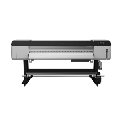
EPSON DFX-5000+ Service Manual
