Crafco SUPER SHOT 125 User manual

SUPER SHOT 125 DIESEL MELTER
PART MANUAL - 26378
REV. E

2
Revised: 05/22/02

3
SUPER SHOT 125 DIESEL MELTER

4
TABLE OF CONTENTS
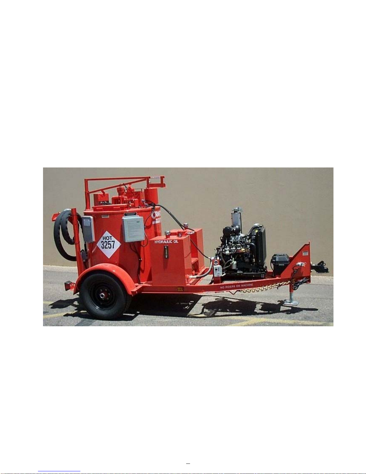
SuperShot125DieselMelter...................................................................................................... 5
SafetyPrecautions....................................................................................................................... 6-7
LimitedWarranty.......................................................................................................................... 7
WarrantyClaimInstructions......................................................................................................... 8
Specifications............................................................................................................................... 9
Introduction...................................................................................................................................10
Operating Instructions
MachineStartUp...................................................................................................... 11-12
DispensingtheMaterial/ActivePump Protection..................................................... 13
Loading The Machine/Shutdown and Clean-out Procedures/Storing Machine.......14
Instructions For Ordering Parts/Electric Hose Care and Cautions.......................... 15
HoseTransportInstructions..................................................................................... 16
Maintenance
MaintenanceInstructions......................................................................................... 17
MaintenanceChart/ServiceInstructions.................................................................. 18
RecommendedFluidsansLubricants/TypicalSpecifications................................. 19
SuperShotPumpReplacement.............................................................................. 20
SuperShotPump Replacement Diagram............................................................... 21
Trouble Shooting
Trouble Shooting Guide - Hose Does Not Heat...................................................... 22
HoseCircuitDiagram............................................................................................... 23
Trouble Shooting Guide - Hose Does Not Heat (continued)................................... 24
Trouble Shooting Guide - Material Does Not Dispense ......................................... 24
HoseCircuitDiagram............................................................................................... 25
Trouble Shooting Guide - Material Does Not Dispense.......................................... 26
Trouble Shooting Guide - Pump Rotates but No Material Is Discharged................ 26
Trouble Shooting Guide - Material Dispening Rate Too Slow................................. 26
HoseCircuitDiagram............................................................................................... 27
RTDSensor - Ohms vs.Temperature...................................................................... 28
DieselBurnerAdjustments/Diesel Burner Settings.................................................. 29
BurnerSchematic..................................................................................................... 30
BurnerTrouble Shooting.......................................................................................... 31
HydraulicSchematic................................................................................................. 32
Trouble ShootingHydraulics.................................................................................... 33
Parts SS125Diesel MelterDiagramsandParts............................................................... 34-39
TankDetail Diagram and Parts................................................................................ 40-41
ControlBoxDiagramandParts............................................................................... 42-43
EngineAssemblyDiagram and Parts...................................................................... 44-45
HydraulicControlValve DiagramandParts............................................................ 46
Pump/AgitatorMotorAssemblyDiagramandParts................................................ 47
DieselBurnerDiagramandParts............................................................................ 48-49
HydraulicDiagramandParts................................................................................... 50-51
ElectricalCablesandParts...................................................................................... 52-53

5
SUPER SHOT
125 DIESEL MELTER
This manual is furnished with each new CRAFCO SUPER SHOT 125 DIESEL MELTER.
This manual will help your machine operators learn to run the melter applicator properly
and understand its mechanical functions for trouble-free operation.
Your CRAFCO SUPER SHOT 125 DIESEL MELTER is designed to give excellent service
and save maintenance expense. However, as with all specially engineered equipment, you
can get best results at minimum costs if:
1. You operate your machine as instructed in this manual.
2. Maintain your machine regularly as stated in this manual.
WARNING: The engine exhaust from this product contains chemicals
known to the State of California to cause cancer, birth defects or other
reproductive harm. Operate in well ventilated area only. Engine exhaust
is deadly.

6
SAFETY PRECAUTIONS
•High operating temperatures of sealant and machine require protective clothing,
hard-soled shoes and heat resistant gloves to be worn by operator.
•Always wear eye protection.
•Observe all CAUTION AND WARNING signs posted on machine.
•Avoid the entrance of water into any part of the machine. Water will displace heat transfer
oil or sealant, which could be hazardous to personnel surrounding the machine when it
reaches operating temperatures.
•Avoid bodily contact with hot sealant material or heat transfer oil, serious burns may
result.
•Read Operator Manual thoroughly before operating machine.
•Make sure operator is familiar with machine operation.
•Do not operate in closed building or confined areas.
•Shut-down burner and engine prior to refilling diesel tank.
•When adding solid material to sealant tank, stop mixer, lift lid, place material onto lid and
close lid before restarting mixer. Hot material could splash and cause serious burns if this
procedure is not followed.
•Keep hands, feet, and clothing away from all moving parts.
•Always keep a fire extinguisher near the unit. Maintain extinguisher properly and be
familiar with its use.
•DO NOT exceed 525°F for heat transfer oil temperature.
•DO NOT overfill heat transfer oil level. Expansion of oil during heat up could cause
overflow. With machine in level position, check oil each day before starting burner, add oil
to top mark on dipstick if required (at 70°F.). Use only recommended heat transfer oil
and change after 500 hours of operation or one year, whichever occurs first.
•Follow operating instructions for starting and shut-down of burner. See Operating
Instructions.
•Calibrate temperature control prior to initial operation and each 50 hours of operation.
See Temperature Control Calibration.

7
SAFETY PRECAUTIONS
•Replace any hoses which show signs of wear, fraying, or splitting. Be sure all fittings and
joints are tight and leak-proof, each time machine is used.
•Precaution is the best insurance against accidents.
•The melter should not be left unattended with burner lit.
•Tighten all bolts and screws after every 100 hours of operation.
•Crafco, Inc. assumes no liability for an accident or injury incurred through improper use of
the machine.
LIMITED WARRANTY
Crafco, Inc., through its authorized distributor, will replace for the original purchaser free of
charge any parts found upon examination by the factory at Mesa, Arizona, to be
defective in material or workmanship. This warranty is for a period within 60 days of
purchase date, but excludes engine or components, tires, and battery as these items are
subject to warranties issued by their manufacturers.
After 60 days, Crafco, Inc., warrants structural parts, excluding heating system, hydraulic
components, material pump and hoses, hot oil pump, applicator valves, and electrical
components for a period of (1) one year from date of delivery. Crafco, Inc., shall not be
liable for parts that have been damaged by accident, alteration, abuse, improper lubrica-
tion/maintenance, normal wear, or other cause beyond our control.
The warranty provided herein extends only to the repair and/or replacement of those
components on the equipment covered above and does not cover labor costs. The
warranty does not extend to incidental or consequential damages incurred as a result of
any defect covered by this warranty.
All transportation and labor costs incurred by the purchaser in submitting or repairing
covered components must be borne by the purchaser.
Crafco, Inc. specifically disavows any other representation, warranty, or liability related to
the condition or use of the product.
WARNING: Use of replacement parts other than genuine Crafco parts
may impair the safety or reliability of your equipment and nullifies any
warranty.

8
WARRANTY CLAIM INSTRUCTIONS
Please follow the instructions stated below when calling in a warranty claim. Failure to
follow these procedures may be cause to void the warranty.
1. Call your local Crafco Distributor. If you do not know who your local distributor is,
call a Crafco Customer Service Representative, (Toll Free 1-800-528-8242) for
name, location, and telephone number.
2. On contacting the distributor, be prepared to identify the machine type, model
number, and serial number, also, the date of purchase if available.
3. Should the cause of the malfunction be a defective part, the distributor will advise
you of the procedure to follow for a replacement.
4. The warranty is valid only for parts, which have been supplied or recommended by
Crafco, Inc.
If you have any additional questions regarding warranty repairs and parts, please do not
hesitate to call toll free 1-800-528-8242.
CRAFCO, INCORPORATED
235 SOUTH HIBBERT DRIVE
MESA, AZ 85210
480-655-8333
Toll Free 1-800-528-8242

9
SPECIFICATIONS
Vat Capacity..................................................................125 Gallons
Melt Capacity................................................................90 Gallons/Hour
Heat Transfer Oil Required...........................................34 Gallons at 70°F.
Tank Construction.........................................................Double Boiler Type
Tank Opening Size....................................................... 14” X 18”
Maximum Heat Input.................................................... 250,000 BTU’s
Burner and Temperature Control..................................Diesel-Forced Air
Thermostatic Control
Engine - Isuzu...............................................................Twin Cylinder
Model 3LB1 - Diesel 25.4 BHP @ 3600 RPM
Hydraulic Drive Mechanism..........................................All hydraulic with infinite
speed on mixer and material
pump.
Mixer.............................................................................Full sweep mixer with two
horizontal paddles
vertical risers.
Axle....................................................................................Single-5,200Lb.Torsional
Tires (2)........................................................................ ST225/75R15 Load Range D
Dry Weight....................................................................Approximately 2,600 Lbs.
Diesel Tank Capacity.................................................... 24 Gallons
Hydraulic Tank Capacity............................................... 24 Gallons

10
SUPER SHOT 125 DIESEL MELTER
OPERATING INSTRUCTIONS
INTRODUCTION
The CRAFCO SUPER SHOT 125 MELTER was developed to melt Crafco brand
sealant. However, it will work well with most road asphalt and federal specification crack or
joint sealant.
DO NOT operate machine without following these instructions:
1. Fill fuel tank with diesel fuel (use #1 in cold weather, #2 in warm weather).
2. Check engine crankcase oil level (refer to Engine Operator’s Manual).
3. Check hydraulic fluid level, at 70°F. Add fluid if necessary.
4. Check heat transfer oil level, at 70°F., the oil should be at the full mark on the
dipstick. DO NOT overfill or spillage may occur when oil is heated and
expands.
5. All toggle switches should be turned “OFF” and both temperature control dials at
minimum settings.
6. Remember that safe operation of this equipment is the operator’s responsibility.
CAUTION:
Extreme care must be used when operating this equipment. Safety is the result
of being careful and paying attention to details. Remember the diesel flame is
about 2,200°F. Certain exposed parts of this machine when operating reach
500°F.; the sealant as high as 400°F. and the hydraulic fluid may reach 200°F.
Always wear protective clothing, hard-soled shoes, and eye protection. Be sure
that all joints and fittings are tight and leak proof. Immediately replace any hose
which shows any signs of wear, fraying, or splitting. Tighten all bolts, nuts, and
screws every 250 hours.

11
MACHINE START UP
TO START BURNER
1. Fully open the damper vent.
2. Start engine per Engine Manual.
3. Turn “POWER” toggle switch at control box “ON”.
4. Set hot oil temperature at 500°F. and material temperature at manufacturers
recommended temperature.
CAUTION:
If burner does not ignite the first time, turn toggle switch to “OFF.” Turn toggle
switch to “ON” again. Burner should ignite. If burner still does not ignite,
determine cause of malfunction (see Trouble Shooting Guide Pg. 22-26).
NOTE: The solid material in the tank melts first around the walls and bottom of the
material tank. Material temperature sensor is located by the wall; therefore, it is
possible that at the beginning of the melting process the indicated temperature
reaches operating value, but the material closer to the center of the tank is still solid.
This is normal and when the heated hose is ready for operation, most of the material
in the tank will be melted and heated to application temperature.
5. Allow the heating oil to continue to heat. When sealant material reaches 275°F.
mixer may be engaged by turning the toggle switch at hydraulic control panel “ON”.
If the mixer does not move, allow the material to heat longer. Jamming of mixer
causes hydraulic oil to overheat and machine damage could occur. NOTE: Mixer
speed is preset at the factory and cannot be adjusted. Mixer cannot be
engaged until material reaches 275°F.
6. Hose will automatically turn “ON” when material temperature reaches approximately
275°F. See Operating Instructions. Adjust the temperature dial to 380°F. or manu-
facturers recommended temperature. The hose will come up to temperature in
approximately 30 minutes. After the hose is hot, the light in the control box marked
“heated hose” will turn off and the temperature may be reduced to approximately
360°F. It is advisable to run the hose at the recommended temperature setting.
NOTE!! The hose must be up to 325°F. before dispensing can take place. If hose
does not dispense when trigger is activated then allow material to heat longer. If
hose still does not dispense material then shut machine down and locate plug in the
line and remove.
IMPORTANT!! DO NOT twist or kink hose. Avoid sharp bends and continuous
twisting. Maintain minimum, 10 inch bend radius. DO NOT exceed 400°F. setting
on hose controller!! DO NOT move or bend hose when cold. Damage may result.
DO NOT leave hose “ON” for longer than 30 minutes without dispensing material.
Coking will occur and permanently damage hose. DO NOT remove hose from boom
during operation, kinking will occur.

12
MACHINE START UP
IT IS STRONGLY RECOMMENDED THAT THE HOSE BE STORED IN THE HOSE
HANGER WHEN NOT IN USE OR WHEN IN TRANSIT. THIS WILL HELP
PREVENT TWISTING OR KINKING.
7. The heated hose supplied with the machine is Teflon lined with steel over braid. It
has a heating element, which runs down the hose to heat the material within the
hose. The hose is covered with high temperature, durable rubber hose. The wand
has an aluminum tube to protect both the wand and the operator. The pistol grip
actuator is equipped with an electric switch which when depressed sends a signal to
actuate the pump. At the end of the wand, a high temperature elastomeric output
valve is attached. The valve is pressure actuated and opens automatically when
fluid pressure is applied. The wand is equipped with a trigger lock to prevent
accidental pump actuation when not pumping material. The trigger should be in the
“LOCKED” position at all times except when intentionally pumping material.

13
DISPENSING THE MATERIAL
NOTE: PROTECTIVE CLOTHING, GLOVES, HARD SOLED SHOES,
AND FACE SHIELD OR SAFETY GLASSES SHOULD BE WORN
WHEN OPERATING OR FILLING THIS EQUIPMENT. READ
ENTIRE MANUAL BEFORE OPERATING.
The wand is equipped with a disposable duckbill valve on the end, which shuts off the flow of
material when the pump is turned off and prevents excessive dripping of material. This valve also
directs the material into a stream for easy application into the crack. Other sealing tips are
available. See your local distributor for options.
Some difficulty may be encountered when starting up on cold days. Although the wand is designed
to heat the material all the way down to the tip, on cold days it may be necessary to place the tip of
the wand under the lid to facilitate material melting in the valve. Insert the wand tip for only a short
time before proceeding.
When the material and the hose have reached proper application temperature, you are ready to
dispense material. Turn the pump speed control to the lowest setting by turning the speed control
knob fully counter clockwise. With the wand tip inserted into the top of the melter, depress trigger
on the wand and slowly increase pump speed by turning the speed control knob clockwise until the
pump motor starts to turn. Material should start to flow from the tip of the duckbill valve. Adjust the
pump speed for the desired rate of flow for the application and dispense material as required. The
rate of flow may be varied while the pump is running by rotating the control knob.
NEVER POINT THE WAND AT ANY PART OF THE BODY OR
AT ANY OTHER PERSON. HOT MATERIALS CAN CAUSE
SEVERE BURNS. WEAR PROTECTIVE EQUIPMENT WHEN
FILLING OR OPERATING THE EQUIPMENT. READ MANUAL
BEFORE OPERATING EQUIPMENT.
ACTIVE PUMP PROTECTION
The pump is completely encircled by a protective screen. The screen shall not allow any-
thing larger than 1/2” (1.27 cm) in size to pass from the sealant tank into the pump suction
port. The screen shall continuously rotate 360 around the pump whenever the sealant
agitator is engaged. The active screen will protect the pump from foreign object damage
and will self clean as it rotates around the sealant pump and suction port.

14
LOADING THE MACHINE
When loading solid material into the sealant tank, the mixer will stop when the lid is lifted.
To load, lift the lid, place the material on the lid and close lid. Following this procedure will
prevent the hot material from splashing and causing serious burns to personnel.
The solid material must be added at intervals, which will allow the mixer to rotate without
jamming. If blocks of material are fed in too quickly, jamming will result and slow down the
melting process.
SHUTDOWN AND CLEAN-OUT PROCEDURE
When shutting down the machine for the day, there are several schools of thought about
how much material to leave in the machine. Crafco recommends leaving the melter about
half full. This will give a fairly rapid heat up rate in the morning, but will allow enough
material to start dispensing right away when the material becomes molten.
1. Reverse the pump for approximately 30 seconds.
2. Turn the “POWER” toggle switch “OFF”.
3. Store the hose in the hose hanger per transport decal on machine.
IMPORTANT!! DO NOT kink or twist hose, as permanent damage will result.
4. Turn the mixer toggle switch to “OFF”.
5. Shut the engine down by turning the key to the “OFF” position.
STORING MACHINE
The melter should be stored in an area where moisture cannot enter the machine heating
system such as hot oil, controls, etc. Extended down time can cause moisture build up in
heating oil tank.
If there is any suspicion that moisture may have collected in heat transfer oil, warm heat
transfer fluid to 300°F. for 2 to 3 hours to evaporate the moisture.

15
INSTRUCTIONS FOR ORDERING PARTS
Parts may be ordered from your local CRAFCO Distributor or directly from CRAFCO, Inc. if
a distributor is not available in your area. When ordering parts, give the following
information:
1. Part number.
2. Machine model.
3. Serial number.
Write, telephone, or fax: CRAFCO, INCORPORATED
420 N. Roosevelt Ave.
Chandler, Az. 85226-2601
Phone: 602-276-0406
Fax: 480-961-0513
Toll Free: 1-800-528-8242
ELECTRIC HOSE CARE AND CAUTIONS
Twisting and kinking of the electric hose (used on LF, BAX, SS60, SS125, and SS250
Melter) is the number one cause of hose failure.
When this happens, the electric heating wires are shorted out to the metal hose cover and
the hose stops heating.
This type of failure is not covered under the Crafco warranty.
To help prevent twisting and kinking and the resulting hose damage, the operator should:
a. Not move or use hose unless it has been turned on at least 30 minutes and
set at a minimum temperature of 300°F.
b. Make sure hose swivel between hose and wand moves freely.
c. Limit the hose bending to a radius of 10 inches.
d. Avoid bending the hose over sharp edges such as the edge of the frame or
tank.
e. Avoid twisting.
f. Do not exceed 400°F. on the hose or material temperature.
g. Follow all instructions of the melter as well as those in the instruction manual.

16
HOSE TRANSPORT INSTRUCTIONS
1. Remove hose from jib support and rotate jib support towards front of machine until it
locks into position.
2. Wrap hose on hose hanger two complete wraps (Approximately 20 inch diameter).
3. Store wand in support hook.
CAUTION:
Hose damage will occur if:
a. Hose is bent or moved when cold.
b. Hose is twisted or bent at less than a 10 inch radius.
c. Hose is moved prior to being turned on at least 35 minutes and set at
380OF.
d. Operator crosses over or under hose causing hose to twist or wires between
hose and wand connection to twist or wrap up.
e. Swivel is cold and not free to move allowing hose to twist.
f. Hose to wand wiring is pulled, stressed, or used to support the wand.

17
MAINTENANCE INSTRUCTIONS
ENGINE
See Engine Owner Manual for operating and maintenance instructions.
HYDRAULIC SYSTEM
Check hydraulic fluid daily. Change hydraulic filter every 250 hours of operation. Change
hydraulic fluid every 500 hours of operation.
HEAT TRANSFER OIL
Check oil level every 8 hours of operation. Change oil every 500 hours of operation.
WHEEL BEARINGS
Re-pack wheel bearings every 24,000 miles or every two years, using a good grade of
bearing grease.
LUG NUTS
Wheel nuts/bolts should be torqued before first road use and after each wheel removal.
Check and retorque after the first 10 miles, 25 miles, and again at 50 miles. Check periodi-
cally thereafter. Torque in stages. 1st stage 20-25 ft.lbs., 2nd stage 50-60 ft.lbs., 3rd stage
90-120 ft.lbs.
TIGHTENING SEQUENCE
BRAKES
Check brakes daily. Refer to DEXTER AXLE Operation Maintenance Service Manual
located in the manual box.
TONGUE JACK
Lubricate tongue jack, using a good grade of bearing grease.
MIXER BEARING
Lubricate every 50 hours with good quality, high temperature grease.
TEMPERATURE CONTROL CALIBRATION
Check control knob calibration weekly.
1. Calibrate by aligning the line on the control knob
with the calibration line on the scale plate (See Fig. 1).
Fig. 1

18
SERVICE INSTRUCTIONS
1. Conduct a general inspection of your machine at least once a week. Replace all
worn or damaged parts, make any necessary adjustments and tighten all loose nuts
or screws.
2. Keep regular replacement items in stock for emergency repairs and to avoid costly
“down” time.
3. Watch for leaks. Tighten fitting or repair as necessary.
4. Clean machine externally periodically. Check with sealant manufacturer for
recommendation.
5. Follow recommended maintenance procedures on maintenance chart.
MAINTENANCE CHART
SRUOH
NOITACOLERUDECORP805052005
levelliokcehcenignE.launaMnoitcurtsnIenignEeeS*
enignerehtO ecnanetniam dnagnitarepOenignEeeS .snoitcurtsnI
ecnanetniaM
yrettaB.ylkeewlevelretawkcehC
liorefsnarttaeH.kcehC*
liorefsnarttaeH.egnahC*
retlifliociluardyH.egn
ahC*
liociluardyH.liokcehC*
liociluardyH.lioegnahC*
renruB
.noitalusnixobrenrubkcehC*
.llecdacnaelC*
.sedortcelekc
ehC*
.sehsurbrewolbkcehC*
.erusserpelzzonkcehC*
sgniraebleehW doogagnisukcap-er&naelC .esaerggniraebfoedarg .s
raeyowtyreveroselim000,42yrevE
kcajeugnoT foedargdooggnisu,esaerG .esaerggniraeb .raeyaecnO

19
RECOMMENDED FLUIDS AND LUBRICANTS
The following is a list of suitable heat transfer oil to be used in Crafco equipment.
TYPICAL SPECIFICATIONS
ISO 68 Viscosity Index 95-100
Flash Point, COC 445°F. Pour Point 0°F.
Viscosity @ 100°F.-SUS 325 Carbon Residue 1%
Viscosity @ 210°F.-SUS 50
WARNING:
The heat transfer oil in this machine is a grade that has been tested and
recommended by Crafco, Inc. The addition of any grade of oil not specifically
recommended by Crafco, Inc., shall be cause for warranties to be voided.
All oils subjected to high temperatures deteriorate with time and lose many of
their characteristics. Tests conducted by Crafco, Inc. have determined that for
best results and safety, the heat transfer oil in this machine must be drained
and replaced with Crafco, Inc. recommended oil after five hundred (500) hours
of operation or one (1) year, whichever occurs first.
NOITACILPPADEDNEMMOCERTNIOPLLUF
lioenignE.launamsrenwouzusIotrefeR.stQ3
leseiD etamilcdloC1# etamilcmraW2# .slaG42
liociluardyHocaxeT86-DHodn
oR.slaG42
liorefsnarttaeH86O&RlageR.slaG43
RECUDORPEMANTCUDORPREBMUNTCUDORP
ocaxeTlageR86O&R
noxxEairolaC34TH
ocrAenelibuR--
ogtiCyrtneS86O&R
.oCliOfluGytiruceS86O&R
.oCliOllehSamrehTC
norvehCliOr
efsnarTtaeHnorvehC--
oconoCliOrefsnarTtaeH86O&R

20
SUPER SHOT PUMP REPLACEMENT
Step 1
Bring melter up to temperature as preparation for draining the material tank. Remove pipe cap located at rear
of machine and drain tank (CAUTION!! EXTREMELY HOT MATERIAL).
Step 2
Remove both guards from the motor mount to access the chain and sprockets.
Step 3
Rotate agitator until connecting link is accessible. Disassemble the connecting link and remove the drive
chain.
Step 4
Loosen set screw in the lower coupling half between the hydraulic motor and the drive shaft.
Step 5
Remove the (4) hydraulic hoses and cap off all ports. Note: Mark hoses for ease of replacement.
Step 6
Remove the (4) bolts holding motor mount on top of melter. Lift off motor mounting and set aside.
Step 7
Remove (2) bolts holding agitator shaft bearing. Note: Do not remove bearing from agitator shaft.
Step 8
When unit has cooled sufficiently, remove (6) bolts holding paddles on top of screen. Remove paddles from
tank.
Step 9
Remove pump drive shaft from center of agitator shaft then lift agitator shaft and screen assembly as high as
possible and insert screw driver into shaft hole. This will support the assembly while removing the pump from
the tank.
Step 10
Remove the (6) bolts, which fasten the pump to the tank. Lift the pump from the material tank (CAUTION!!
THE PUMP WEIGHS APPROXIMATELY 90LBS.)
Step 10
IMPORTANT:Clean any sealant from top of pump mounting plate and clean-out shaft holes. (WARNING!!!
PREMATURE PUMP WEAR WILL OCCUR IF THIS IS NOT DONE.)
Disassembly of Material Pump
Step 11
Remove the (2) bolts, which hold the pump plates together. Disassemble the (3) plates from each other
(NOTE: as pump is being disassembled make note of the orientation of holes in each plate).
Step 12
Clean all pump parts thoroughly before beginning to reassemble the pump.
Step 13
Assemble the pump, check for free movement of the pump gears. If gears do not turn freely, loosen bolts
slightly and align plates until the gears turn freely. Torque all the bolts to 35 ft. lbs.
Step 14
Install all parts in machine starting at: Step 10 and working backward to Step 1.
Other manuals for SUPER SHOT 125
1
Table of contents
Other Crafco Melting Machine manuals
Popular Melting Machine manuals by other brands

VALCO MELTON
VALCO MELTON ISOMELT user manual

CPMG
CPMG Magma M1 Owner's/operator's manual

Chandler And Me
Chandler And Me CMP-15-ANZ user manual

3M
3M Scotch-Weld AE II LT quick start guide

CIMLINE
CIMLINE C1 Owner's/operator's manual

Viega
Viega ProRadiant Basic Digital Snow Melt Control... Product instructions