CIMLINE MATRIX 1500 Owner's manual

2601 Niagara Lane · Plymouth, MN 55447 · (763) 557-1982 · (800) 328-3874 · Fax (763) 557-1971
Melter Applicator
Owner / Operator Manual
(Includes Safety and Service Information)
Part # 161073 Revised 1/31/08
Melter Applicator

- 2 -
Table of Contents
Shipping Papers and Information ..................................................................................... 3
Safety Notes........................................................................................................................ 4
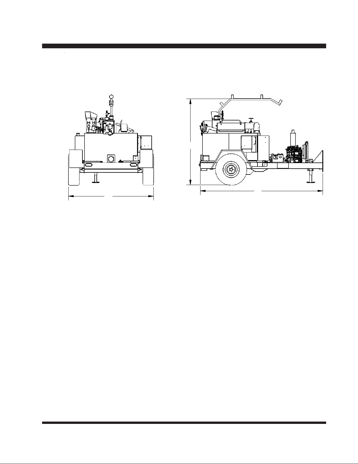
Dimensions and Weights ................................................................................................... 5
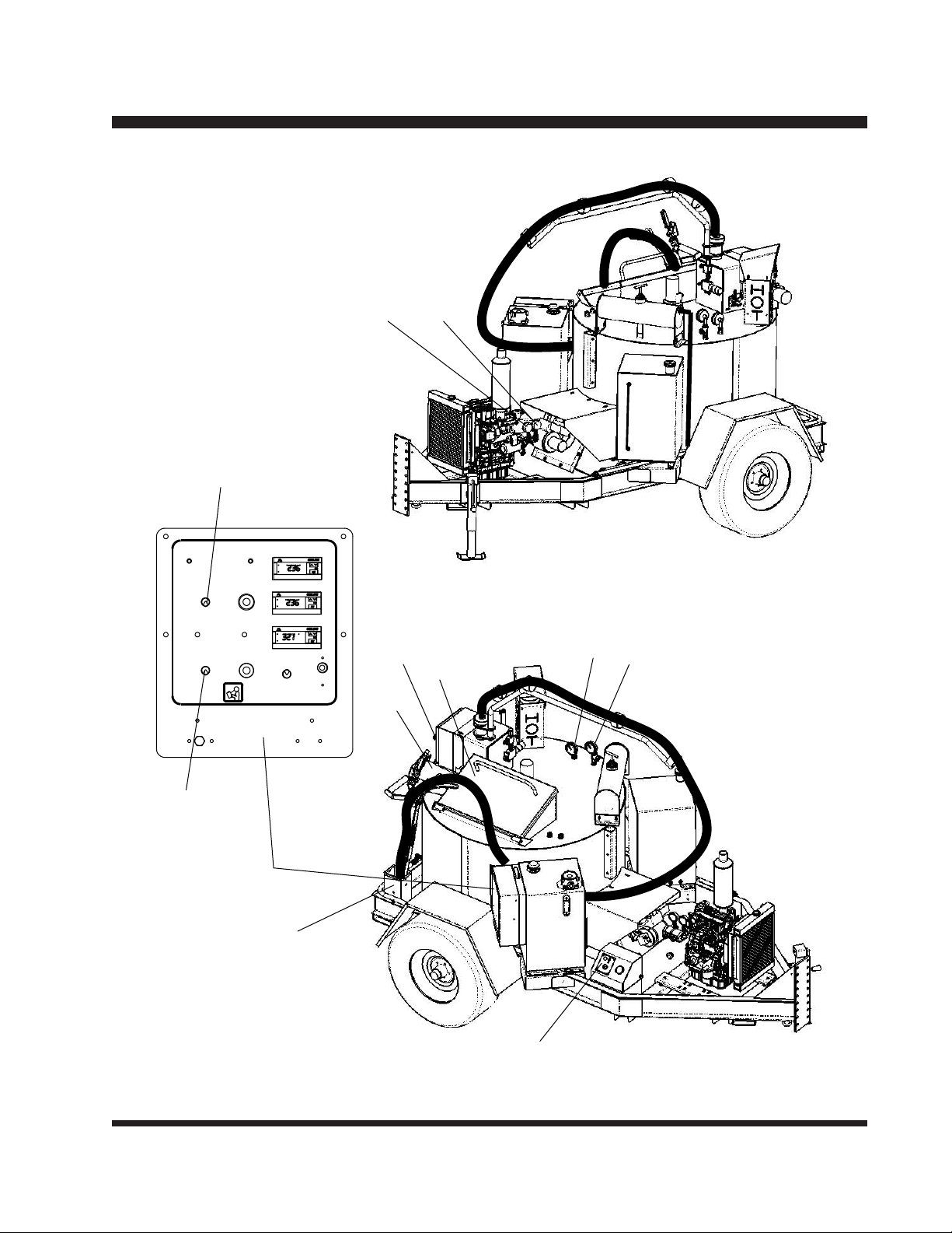
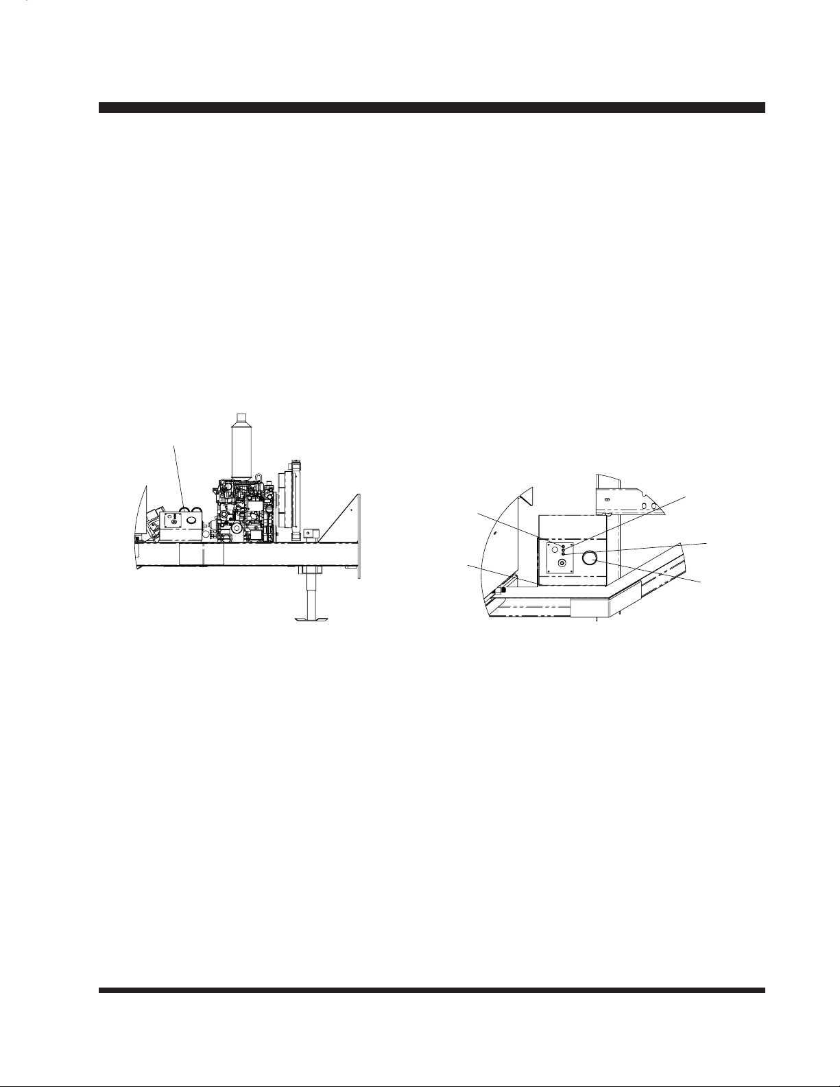
Controls and Their Functions ........................................................................................... 6
Operating Sequence .......................................................................................................... 8
Starting the Engine.............................................................................................................9
Automatic Temperature Control Setting......................................................................... 10
Setting Temperature Controllers..................................................................................... 11
Material Loading Procedure ............................................................................................ 12
Sealing Procedure ............................................................................................................ 12
Material System Cleanout ................................................................................................ 13
Electric Eye and Fuse Inspection ................................................................................... 14
Burner Motor Brush Inspection ...................................................................................... 14
Burner Nozzle Replacement ............................................................................................ 15
Chamber Lining Inspection ............................................................................................. 15
Adjusting Replacement Burner ....................................................................................... 16
Adjusting Fuel Pump Pressure ....................................................................................... 17
Adjusting Burner Nozzle, Electrode and Head Position ............................................... 18
Maintenance...................................................................................................................... 21
Fluid and Components Specifications ........................................................................... 22
Heat Transfer Oil Specifications ..................................................................................... 23
Material Tank Capacity ..................................................................................................... 24
Trouble Shooting Guide ................................................................................................... 25
Hydraulic Schematic ........................................................................................................ 26
Primary Control ................................................................................................................ 27
Wiring Diagrams ............................................................................................................... 28
Wiring Diagrams ............................................................................................................... 29
Electrical Components .................................................................................................... 30
Diesel Engine Components ............................................................................................. 31
Sealing Attachments ........................................................................................................ 32
Sealing Hose Accessories ............................................................................................... 33
Plumbing System Parts List ............................................................................................ 34
Plumbing System Parts List ............................................................................................ 35
Oil Burner Parts List ........................................................................................................ 36
Combustion Chamber Parts List..................................................................................... 37
Hydraulic and Fuel Tank Components ........................................................................... 38

- 3 -
A packet containing IMPORTANT INFORMATION has been enclosed with your Melter.
This packet contains:
1) Operation Instructions
2) Parts List
3) Warranty Information
4) Manufacturer's Documents
a) Engine
b) Material Pump
c) Burner (Diesel only)
d) Parts/ Wiring Manual
IMPORTANT: This manual contains the basic information required to operate, maintain
and repair the CIMLINE Melter you have purchased. The use of this manual insures accu-
rate adjustments, operation and proper lubrication of your equipment. Please keep it
handy.
Any parts orders or service problems relating to CIMLINE equipment should be directed to
the CIMLINE Parts Department at either (763) 557-1982 or (800) 328-3874. When order-
ing parts, please have the following information available.
Serial Number: ____________________________
Model Number: ____________________________
Engine Model (H.P.): ____________________________
Engine Manufacturer: ____________________________
Pump Number: ____________________________
Replacement Part Number(s):
Shipping Papers and Information

- 4 -
PLEASE READ AND UNDERSTAND ENTIRE OPERATORS MANUAL BEFORE
PROCEEDING
WARNING: Protective clothing must be worn. Refer to ANSI Regulations:
1) Wear gloves with wristlets.
2) Wear long sleeve shirt with sleeves rolled down and cuffs buttoned.
3) Wear a face shield.
4) Load Melter from ground level.
5) Keep material door closed at all times except when adding material.
6) Never stand on any part of the machine.
7) Do not pull, twist, stretch or kink the material hose.
8) Do not operate without safety cover on hose.
9) Do not touch exhaust stacks or mufflers.
10) Wear heavy leather boots or shoes.
11) Wear long pants with no cuffs.
WARNING: Do not over fill the melting tank. For best results, add only as much
material as required for the job or a maximum of 75% of tank capacity.
(Model 1500-112 gallons.)
WARNING: On a new Melter applicator or a unit that has been idle for some time,
slowly raise the oil temperature to 250º F and hold there for approxi-
mately 20 to 30 minutes. This will help get rid of any condensation that
may be in the oil chamber.
WARNING: Never leave machine unattended while it is running.
Safety Notes

- 5 -
Dimensions and Weights
Model 1500 Shown

- 6 -
Controls and Their Functions
NOTE: This general outline will only familiarize you with the machine. Read through
the entire manual before putting this machine into operation. (Refer to Dia-
gram 1 on page 9)
1) Access Port: The sealing wand is placed in here when not in use. This allows
operator to continue circulating material through the hose to prevent material from
cooling and freezing up.
2) Loading Door Place the material on safety door to load the melting tank.
3) Oil Temperature Gauge: Monitors the heat transfer oil temperature.
4) Material Temperature Gauge: Monitors the heat of the material in the tank.
5) Pressure Valve: This valve controls the flow rate of the material being pumped to
the hose and sealing wand by changing the pressure setting. (Turning the valve
clockwise will increase the pressure which in turn will increase the flow). During
sealing operations, this valve alone can be used to regulate flow.
6) Agitation Drive Control Switch: Flip this toggle switch to the forward-off-reverse
fuction.
7) Pressure Gauge: This gauge measures the pressure required to turn the agitator.
By observing this gauge, the operator can tell if the agitator is rotating.
8) Pump Drive Control Switch: Flip this toggle switch to the forward-off-reverse
fuction.
9) Temperature Control Box: This control allows the operator to set the desired oil
and material temperatures. The setting will be maintained automatically.
10) Wand Holder: On models with the electrically heated hose, the wand is placed into
this holder..
11) PSI Gauge: This gauge will tell you the amount of pressure in the hydraulic system.
12) Ignition: This will allow you to start the engine. (This must be turned on to allow
the machine to start.

- 7 -
1
23
4
5
6
TM
X
MATRI 1500
READ OWNER'S MANUAL
BEFORE OPERATING
OFF
Material Tempature
(See Matl Spec Sheet)
Oil Tem pature
(Max 550°F)
Heated Hose
Tempa ture (Max 400°F)
Material Pump
Forward
Off
Reverse
Off
Reverse
Agitator
Forward ON
Heated
Hose
Circuit
Indicator
Light
Indicator
Light
BY CIMLINE EQUIPMENT
2601 Niagara Lane
Minnea polis, MN 55447 U.S.A.
800-328 -3874
(15 Amp)
Heated
Hose
711
8
10
9
12

- 8 -
Operating Sequence
NOTE: This step by step procedure is only an outline. Refer to the page(s) indi-
cated for complete instructions.
PROCEDURE: PAGE
1) Place wand in return port . 6
2) Switch pump and agitator toggle switch to the forward position.
10
3) Start engine per engine operating instructions. 9
4) Add material, typically 2-3 biscuits if tank is empty. 12
5) Adjust flow to sealing wand.
12
6) Remove Wand and start sealing. 12
Once the oil temperature reaches 325deg F, the agitator will start rotating.
Once the Material temperature reaches 350 Deg F, the material pump will start.
At the end of the Day
1) Return Wand to Access Port and pin trigger 6
2) Switch the material toggle switch to the reverse operation and allow to run 2 min. 12
3) Turn engine off and remove key. 12
4) Lock hose boom in tow position.
5) Always secure sealing wand, sealing hose and hose boom
before towing the Melter.
NOTE: When leaving reheatable material in tank, allow the agitator to run until the
oil and material temperatures are the same.

- 9 -
Starting the Engine
Starting the Engine
NOTE: Read the engine instruction manual before starting.
Engine RPM is factory set and fixed at 3000 RPM.
Diesel Engine:
Your Isuzu Diesel Powered Melter is equipped with an electronic shutdown system . If the
system detects excessive water temperature, low alternator output, or low oil pressure, the
engine will automatically shut down. The indicator light that remains on indicates the mal-
function. An integral digital hourmeter records engine run time,
The engine must be running before igniting the burner. The burner will only operate if the
ignition key is turned on. DO NOT turn on burner without engine running.
Water
Temperature
Charging
System
Oil
System
Hour
Meter
Battery Box
Battery
Box

- 10 -
Automatic Temperature Control Setting
NOTE: On diesel units, the engine must be running before activating temperature
control. The automatic temperature control system monitors the heat trans-
fer oil temperature and material temperature.
1) Set the oil controller (A) to 550º F(288º C) (See Setting Temperature Controllers, pg.
17)
2) Set the material controller (B) to the recommended material working temperature
which is typically listed on the material container.
3) Turn switch (H) on to activate the heated hose.
4) Set the heated hose controller (C) to350º. Light (J) will be on when the controller is
calling the generator to activate.
5) Turn rocker switchs (D) and (K) to the forward position.
A
G
C
H
B
F
J
G
I
E
K
D
MATRI 1500
X
TM
Heated
Hose
(15 Amp)
BY CIMLINE EQUIPMENT
2601 Niagara Lane
Minneapolis, MN 55447 U.S.A.
800-328-3874
Indicator
Light
Indicator
Light
Heated
Hose
Circuit
ON
Agitator
Forward
Reverse
Off
Reverse
Off
Material Pump
Forward
Heated Hose
Tempature (Max 400 F)
Oil Tempature
(Max 550 F)
Material Tempature
(See Matl Spec Sheet)
OFF
READ OWNER'S MANUAL
BEFORE OPERATING
When lights (G) and (F)
are on, the burner has
been activated.
Light (E) will only be on
when the material tem-
perature is above 350º.
(this signals the material
pump to come on.
Light (I) will only be on
when the oil temperature
is above 325º. (this sig-
nals the agitator to come
on).

- 11 -
Setting Temperature Controllers
"PFo" indicates broken or absent probe.
"PFc" indicates short circuited probe.
Increase (UP)
Decrease (DOWN)
A
B
1) Press and hold set button (A) for 5 sec. Light (B) will turn on while in the setting
mode.
2) Press "UP" or "DOWN" button until desired temp is shown.
3) Press set button (A) , light (B) will turn off and the readout will display actual
temperature.
4) Indicator light (B) will remain on anytime the burner is running.
NOTE: Press set button (A) at anytime to display the setpoint temperature.
For safety, the high limit settings are locked in at the factory to prevent overheating. The
settings are:
Oil Controller- 550º F (288º C)
Material Controller- 450º F (232º C)
Heated Hose Controller- 400º F (218º C)
These settings can be field adjusted for specific applications.
Consult the factory for instructions.

- 12 -
Sealing Procedure
1
2
3
1) Turn flow control valve (A) counter clockwise until valve bottoms out.
2) With wand in access port (B) and the trigger pinned, open loading (C) door and
increase flow valve (A) until the desired flow has been achieved.
3) Close loading door (C) and unpin wand trigger.
4) Pull wand from access port and proceed to joint or crack to be filled.
5) Place the sealing tip into the joint, press trigger and begin sealing by dragging tip
through the joint.
6) If the flow rate is incorrect, repeat steps 1 through 5.
7) As you approach the end of the joint, depress the trigger to avoid access spillage.
Loading Empty Tank
1) All material must be clean. Keep all
foreign matter out of melting tank.
2) Open the material door (1) and place
slab or biscuit (2) on the open door
against the holder (3).
3) Push door to the closed position. DO NOT DROP MATERIAL INTO THE MELTER
WITH DOOR OPEN.
A
B
C
8) To avoid material
freezing in the
hose, always return
the wand to the
access port and pin
the trigger to allow
material to circulate
through the hose.
Material Loading Procedure

- 13 -
Material System Cleanout
NOTE: The material loading doors and wand access port must be closed at all
times.
REVERSE FLOW CLEANOUT METHOD (Diagram 13)
1) To clean out the machine at the end of the day, return the wand to the access port
(B) and pin trigger. Go to the Run the pump in reverse for 2 - 3 minutes.
2) Go to the control box and flip the pump toggle switch to the reverse mode (see
page 10). Run the pump in reverse for 2 - 3 minutes.
3) Turn off engine (see page 9).
4) Return pump toggle to the forward operation.
5) Unpin and remove wand from access port and place in wand holder.
FLUSHING NON-REHEATABLE MATERIALS
(must have optional draincock)
1) Pump the material tank as low as possible and open draincock to empty tank.
2) Add 5 to 10 gallons of recommended flushing solvent to tank through the access
port.
3) Place the wand into access port and open wand valve.
4) Circulate the solvent approximately 5 to 10 minutes.
5) Pump the solvent through the wand into a container and dispose of it according to
EPA
guidelines.
6) Add another 5 to 10 gallons of material and circulate for 5 minutes.
7) Pump this 5 to 10 gallons into empty containers and reuse it for the first purge next
time the unit is used.

- 14 -
Burner Motor Brush Inspection
Electric Eye and Fuse Inspection
Diesel Burner - Electric Eye Inspection
The diesel burner is equipped with an electronic eye which detects the presence of a
flame. If the eye does not detect a flame after ignition, it will shut down the burner.
B
CD
A
Primary Control
Periodically this eye will get covered
with soot or dirt from the burner. If your
burner lights and then shuts down
immediately, you can normally expect
the problem to be a dirty electric eye.
To clean the eye, simply loosen the two
retaining clip screws (A) and rotate the
clips which hold the hinged spark box
(B) to the burner. Gently wipe the eye
(C) with a soft cloth and reattach the
spark box.
After cleaning the eye, if the burner will
not stay ignited after initial firing, check
fuse located inside the primary control
box. You can open the box by loosen-
ing the two screws (D) and removing the
box.
Due to the high current draw of the burner motor, it is advised to inspect the brushes for
excessive wear every 100 hours of operation. If the brushes are worn out completely it will
stop the motor and typically damage or destroy the ignition transformer assembly.
The brushes can be inspected and installed in a matter of minutes as follows:
C
B
1/8"
1) Remove the brush caps (A) with a
standard straight slot screw driver.
2) Remove the brushes (B) and inspect.
If there is less than 1/8" of brush re-
maining, replace it immediately. If not,
reinstall existing brush.
3) Be sure the radius (C) of the brush
follows the curvature of the motor as
shown below.
4) When the brushes are worn close to 1/
8", check frequently to avoid failure.
A

- 15 -
A
C
B
Chamber Lining Inspection
After each 200 hours of operation, the chamber lining should be inspected. Remove (8)
burner mount securing bolts (A) and pull out burner and mount. Inspect lining (B) for ex-
cessive cracking. Also check the condition of retainer (C). Lining cracks are acceptable as
long as they are not large enough to allow flame to contact the combustion chamber walls.
Burner Nozzle Replacement
During operation, oil is forced through the
burner nozzle at 140 PSI to permit the fuel
to be atomized for easy ignition. The
nozzle orifice has normal wear due to this
high pressure. Due to the high wear, it is
recommended that the nozzle be replaced
at least once per operating season. To
replace the nozzle, remove the burner from
chamber. Remove the two screws which
secure the burner head (A) to the air tube
(B). Carefully insert a 5/8" deep well
socket over the nozzle (C) and turn it
counterclockwise to remove. Be very
careful not to bend the electrodes (D) while
performing this task. When installing the
new nozzle, do not touch the filter portion
(E) of the nozzle. The filter is so fine that
oil from your skin can clog the filter.
B
A
C
E
D

- 16 -
To adjust excess air flow into the burner: (Diagram 14)
1) Loosen screw (A) and rotate air band (B) to the wide open position, then tighten
screws.
2) Loosen 2 screws (C) and rotate the air shutter (D) until the pointer arrow (E) points
to the number 8 setting.
3) Start the burner and allow it to run for about 10 minutes.
4) Loosen the viewport retaining bolt (F) and swing cover (G) out of the way as shown.
5) While observing the flame through the view port , decrease the air shutter (D) by
rotating it until the flame tip appears slightly smoky, then increase the air until the
flame clears up. The arrow (E) should be in the vicinity of 7 - 10. Tighten two screws
(C).
6) Close and secure viewport.
The excess air adjustments on the Beckett ADC burner are essential to prevent the poten-
tial damage to the burner and the burner combustion chamber. Excess air is required to
insure that the carbon and hydrogen are supplied with enough oxygen to burn completely.
If there is not enough excess air, the unit will smoke inside the combustion chamber and
eventually lead to unburned fuel residue left in the chamber. The function of the combus-
tion chamber is to reflect and retain heat to insure that all the atomized oil is burned.
Even a slight amount of soot can decrease the effectiveness of the chamber. It is esti-
mated that 1/8" of soot is equivalent to approximately a 1" thick fiberglass sheet.
With too little excess air, eventually the unburned fuel accumulates into the lining material.
Eventually it will burn even when the burner is turned off. The heat generated by this flame
will vent out through the burner and can cause internal damage to the burner. Typically it
will damage the plastic coupling which operates the fuel pump and it can also damage the
primary control unit. Other common problems include blackening and even distorting the
optic eye.
The burner is factory set with the air band (B) at the wide open position and the air shutter
(D) adjusted typically between the 8 and 10 setting. Decreasing the excess air settings can
lead to the chamber fires as outlined above.
Note that as the nozzle wears, the flame characteristics will change. It is important to
check the nozzle periodically and replace it each year as outlined in the owners manual.
Adjusting Replacement Burner

- 17 -
The fuel pressure is factory set @ 140 PSI. As the pump wears, it may require adjustment
as follows:
1) If your unit is not already equipped with a fuel pressure gauge, remove plug (H) and
insert a 0-200 psi gauge.
2) With the pump running, loosen jamnut (J) and turn screw (K) clockwise to increase
the pressure, CCW to decrease pressure.
3) Hold the screw (K) with a screwdriver while tightening jam nut (J).
Adjusting Fuel Pump Pressure

- 18 -
Adjusting Burner Nozzle, Electrode and Head Position
Your CIMLINE 110, 230 or 410 Melter is equipped with a model ADC burner. Each unit
comes with a nozzle, electrode and head position gauge. For optimum performance, the
steps below should be performed periodically. The burner must be removed from the
combustion chamber.
Step 1: Setting the Electrode Gap
Check electrodes to see if the gap is aligned with the lines on the gauge. The gap should
be
from 1/8" to 5/32" as shown below. Bend the electrodes slightly if required. If the elec-
trodes are way out of line, you may have to remove the head and realign as described in
Step 3.
Step 2: Inspecting Nozzle Concentricity
The nozzle should be approximately centered within the head. Insert the gauge as shown.
The center of the nozzle should be aligned with the center line. Rotate the gauge and
check alignment from several locations. BE CAREFUL NOT TO SCRATCH THE SUR-
FACE. If it is not concentric, you may have to replace or straighten center bracket.
P/N 152668
Centering bracket

- 19 -
Adjusting Burner Nozzle, Electrode and Head Position
Step 3: Setting Electrode Position
Insert gauge as shown below. The electrode tip should be in line with the intersection of
the cross hairs labeled "DC". If not, you must remove the head, then loosen the electrode
retaining screw just enough to allow you to slide the electrodes into the proper location.
Tighten the screws and replace the head.
Step 4: Setting Nozzle Position
Insert the gauge against the head. The end of the gauge should now touch the nozzle. If
not, slightly loosen the knurled nut and the screw on the escutcheon plate until the entire
nozzle assembly can be moved forward or backward. Adjust accordingly and tighten
the knurled nut and screw.
Electrode retaining screw
Escutcheon Plate
Knurled Locknut
Screw

- 20 -
Maintenance
Engine: The operation and life of the engine depends on you and your operator. Do not
start engine until the engine precheck is complete. The engine precheck consists of check-
ing the oil, the fuel level, the hydraulic oil level and the air filter. Basic engine mainte-
nance is shown in Table 1 on page 34. For more detailed information please refer to the
Engine Operator Maintenance Manual and Warranty provided with your Melter applicator.
NOTE: When breaking in a new Melter, we recommend running the engine for one
hour with no load prior to actual use on the job.
Air cleaner: Due to the dusty conditions that can be created by road work, it is essential to
check the engine air cleaner element daily. Remove element and shake out the accumu-
lated dust and dirt. Wipe out dirt from inside cover and from housing. Check engine
manual for washing instructions. We recommend stocking replacement filters.
Lubrication: The Melter should be greased according to table 1 on page 40 of this
manual.
Diesel Units: Use of high quality detergent oil of API (American Petroleum Institute) service
class CC or CD grade. Select the viscosity based on the air temperature at
the time of operation. Check your engine manual for other recommenda-
tions.
Burner: There are several items that need to be inspected periodically on the burners.
These items include the burner motor brushes, the nozzle, electrode and head position,
chamber lining and the 4 electric eye. Inspect according to table 1 on page 40. There is a
section on how to perform each of these operations in this manual, check the index on
pages 2 & 3 to locate the appropriate section.
Other manuals for MATRIX 1500
1
Table of contents
Other CIMLINE Melting Machine manuals