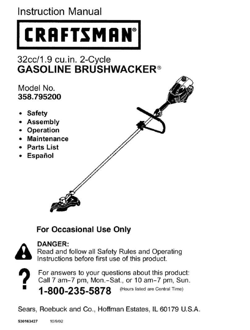
Craftsman 316.792440 User manual

Operator's Manual
M
UNIVERSAL BRUSHCUTTER ATTACHMENT
Model No. 316.792440
CAUTION: Before using this product,
read this manual and follow all its Safety
Rules and Operating instructions.
,, SAFETY
o ASSEMBLY
OPERATION
MAINTENANCE
PARTS LIST
ESPANOL, R 15
Sears Brands Management Corporation, Hoffman Estates, IL 60179 U.S.A.
Visit our website: www.craftsrnan.corn
769-07354 P00 11/11

TABLEOFCONTENTS
Safety............................................... 2
Warranty............................................. 4
KnowYourUnit........................................ 5
Specifications......................................... 5
Assembly............................................. 6
Operation............................................. 9
Maintenance......................................... 10
CleaningandStorage.................................. 12
RepairProtectionAgreements........................... 14
PartsList............................................ 31
ServiceNumbers.............................. BackCover
Allinformation,illustrationsandspecificationsinthismanualarebased
onthelatestproductinformationavailableatthetimeofprinting.We
reservetherighttomakechangesatanytimewithoutnotice.
Thepurposeofsafetysymbolsistoattractyourattentionto
possibledangers.Thesafetysymbols,andtheirexplanations,
deserveyourcarefulattentionandunderstanding.Thesafety
warningsdonotbythemselveseliminateanydanger.The
instructionsorwarningstheygivearenotsubstitutesforproper
accidentpreventionmeasures.
SYMBOL MEANING
DANGER: Signals an EXTREME hazard.
Failure to obey a safety DANGER signal WILL result in
serious injury or death to yourself or to others.
WARNING: Signals a SERIOUS hazard.
Failure to obey a safety WARNING signal CAN result in
serious injury to yourself or to others.
CAUTION: Signals a MODERATE hazard.
Failure to obey a safety CAUTION signal MAY result in
property damage or injury to yourself or to others.
Read the operator's manual and follow all warnings and safety
instructions. Failure to do so can result in serious injury to the
operator and/or bystanders.
NOTE: Advises you of information or instructions vital to the
operation or maintenance of the equipment.

•iMPORTANT SAFETY iNSTRUCTiONS
READ ALL iNSTRUCTiONS BEFORE OPERATING
o
o
o
o
o
o
o
o
o
WARNING: When using the unit, all safety rules must be
followed. Please read these instructions before operating
the unit in order to ensure the safety of the operator and any
bystanders. Please keep these instructions for later use.
Carefully read and understand the operator's manual of the unit
that powers this attachment.
Read the instructions carefully. Be familiar with the controls and
proper use of the unit.
Do not operate this unit when tired, ill or under the influence of
alcohol, drugs or medication.
Children must not operate the unit. Teens must be accompanied
and guided by an adult.
All guards and safety attachments must be installed properly
before operating the unit.
inspect the unit before use. Replace damaged parts. Check for
fuel leaks. Make sure all fasteners are in place and secure.
Replace parts that are cracked, chipped, or damaged in any
way. Do not operate the unit with loose or damaged parts.
Carefully inspect the area before starting the unit. Remove all
debris and hard or sharp objects such as glass, wire, etc.
Be aware of the risk of injury to the head, hands and feet.
Clear the area of children, bystanders and pets; keep them
outside a 50-foot (15 m) radius, at a minimum. Even then, they are
still at risk from thrown objects. Encourage bystanders to wear
eye protection. Ifyou are approached, stop the unit immediately.
SAFETY WARNINGS FOR GAS UNITS
WARNING: Gasoline is highly flammable and its vapors
can explode if ignited. Take the following precautions:
• Store fuel only in containers specifically designed and approved
for the storage of such materials.
Always stop the engine and allow it to cool before filling the
tank. Never remove the fuel tank cap or add fuel when the
engine is hot. Always loosen the fuel tank cap slowly to relieve
any pressure in the tank before fueling.
Always mix and add fuel in a clean, well-ventilated outdoor area
where there are no sparks or flames. DO NOT smoke.
Never operate the unit without the fuel cap securely in place.
Avoid creating a source of ignition for spilled fuel. Wipe up any
spilled fuel from the unit immediately, before starting the unit.
Move the unit at least 30 ft. (9.1 m) from the fueling source and
site before starting the engine. DO NOT smoke.
Never start or run the unit inside a closed room or building.
Breathing exhaust fumes can kill. Operate this unit only in a well
ventilated outdoor area.
J
WHILE OPERATING
Wear safety glasses or goggles that meet ANSi Z87.1-1989
standards and are marked as such. Wear ear/hearing protection
when operating this unit. Wear a face or dust mask if the
operation is dusty.
Wear heavy long pants, boots, gloves and a long sleeve shirt. Do
not wear loose clothing, jewelry, short pants, sandals or go
barefoot. Secure hair above shoulder level.
Make sure the attachment is not in contact with anything before
starting the unit.
Use the unit only in daylight or good artificial light.
Use the right tool. Only use this tool for its intended purpose.
Always hold the unit with both hands when operating. Keep a
firm grip on both handles or grips.
Do not overreach. Always keep proper footing and balance. Take
extra care when working on steep slopes or inclines.
Keep hands, face, and feet away from all moving parts. Do not
touch or try to stop moving parts.
Do not operate the unit faster than the speed needed to do the job.
Do not run the unit at high speed when not in use.
Use extreme caution when reversing or pulling the unit towards you.
DO NOT force the unit. It will do a better, safer job when used at
the intended rate.
Always stop the unit when operation is delayed or when walking
from one location to another.
If you strike or become entangled with a foreign object, stop the
unit immediately and check for damage. Do not operate before
repairing damage. Do not operate the unit with loose or
damaged parts.
Use only original equipment manufacturer (OEM) replacement
parts and accessories for this unit, as listed in the Parts List
section of this manual. Use of any other parts or accessories
could lead to serious injury to the user, or damage to the unit,
and void the warranty.
Keep the unit clean of vegetation and other materials that may
become lodged between the brush blade and blade shield.
If the unit starts to vibrate abnormally, stop the unit immediately.
inspect the unit for the cause of the vibration. Vibration is
generally an indicator of trouble.
OTHER SAFETY WARNINGS
All service, other than the maintenance procedures described in
this manual, should be performed by a Sears or other qualified
service dealer.
Before inspecting, servicing, cleaning, storing, transporting or
replacing any parts on the unit:
1. Stop the unit.
2. Make sure all moving parts have stopped.
3. Allow the unit to cool.
4. Disconnect the spark plug wire.
The brush blade becomes very sharp from use. Always wear heavy
gloves when handling, replacing or cleaning the brush blade.
Never store the unit with fuel in the tank, inside a building where
fumes may reach an open flame (pilot lights, etc.) or sparks
(switches, electrical motors, etc.).
Be sure to secure the unit while transporting.
Store the unit in a dry place, secured or at a height to prevent
unauthorized use or damage. Keep out of the reach of children.
Never douse or squirt the unit with water or any other liquid.
Keep handles dry, clean and free from debris. Clean after each
use, see Cleaning and Storage instructions.
Keep these instructions. Refer to them often and use them to
instruct other users. If you loan this unit to others, also loan
them these instructions.
SAVE THESE INSTRUCTIONS
3
,, SAFETY & iNTERNATiONAL SYMBOLS ,,
This operator's manual describes safety and international symbols and pictographs that may appear on this product. Read the operator's
manual for complete safety, assembly, operating and maintenance and repair information.
SYMBOL MEANING
:_ •SAFETY ALERT SYMBOL
indicates dangeB waining oi Caution: Mayb eUsed
Jm I conjunction with other symbols or pictographs:
oREAD OPERATOR'S MANUAL
I WARNING: Read the oPerator;S manUai(Sl and
fo!!ow al! warnings and safety instruct!onsi Eai!ure t°
.... .... de so can resu t n Set oUS nJUrYtOthe cpe[ator
and/or bystanders;
4t _ ,, WEAR EYE AND HEARING PROTECTION
WARNING: Thrown objects and !oud noiSe can
,-_-il | m cause severe eye injury and hearing loss: Wear eye
Pprotection meeting ANSI Z87:1 _1989 Standards and
ear protecti0n when operating this unit, Usea fu!! face
shield when needed.
SYMBOL
._lQ
MEANING
THROWN OBJECTS AND ROTATING CUTTER CAN
CAUSE SEVERE iNJURY
WARNING: Small objects can be propelled at high
speed, causing injury Keep away from the rotating rotor.
_, bKEEP BYSTANDERS AWAY
_I_ WARNING: Keep all bystanders, especially children
_. and pets, at least 50 feet (15 m) from the operating area.
_TRIMMER/BRUSHCUTTER SAFETY
WARNING: Thrown objects and rotating cutter can
i cause severe injury. Keep bystanders, especially
_._ hildren and pets at least 50 feet (15 m) away from
the cutting area. The cutting attachment shield must
be used when using the trimmer cutting attachment.
CRAFTSMAN TWO YEAR FULL WARRANTY
FOR TWO YEARS from the date of purchase, this product is warranted against any defects in material or workmanship. A defective product
will be replaced free of charge.
For warranty details to obtain free replacement, visit the web site: www.craftsman.com
This warranty does not cover the blade, which is an expendable part that can wear out from normal use within the warranty period.
This warranty is void if this product is ever used while providing commercial services or if rented to another person.
This warranty gives you specific legal rights, and you may also have other rights which vary from state to state.
Sears Brands Management Corporation, Hoffman Estates, IL 60179

APPLiCATiONS
Asabrushcutter:
• Cuttingweedsandlightbrushofupto1/2inchindiameter
Otheroptionalaccessoriesmaybeusedwiththisunit.
TOOLS REQUIRED:
Phillips Screwdriver
Pliers
Shoulder
Harness Loop
Hanger
Small Crescent Wrench
Shoulder Harness 24 in. J-Handle
Assembly w/Hardware
Gearbox
®
® ®
®
Blade Shield
Locking Rod
Approximate Unit Weight (attachment only) ................................................................. 3.75 Ibs. (1.7 kg)
Cutting Path Diameter, Cutting Blade ........................................................................ 8 in. (204 mm)
Shoulder Harness ..................................................................................... single quick snap
* All specifications are based on the latest product information available at the time of printing. We reserve the right to make changes at any
time without notice.
5

Beforeusingthebrushcutteradd-on,someadjustmentsmustbe
madetothetrimmer.Suchas:
• Removethecurrentassisthandle
Installthesupplied24"J-handle
Installtheshoulderstrapclip(ifnecessary)
Attach/adjusttheshoulderstrap
REMOVING THE CURRENT ASSIST HANDLE
The trimmer may be configured with one of several types of assist
handles. The current assist handle must be removed and the 24" J-
handle, which is included, must be installed in order to use this add-
on.
Follow the instructions outlined in the trimmer's operator's manual
in order to remove the current handle and its clamps, screws, nuts,
bolts or other hardware.
NOTE: The trimmer may be equipped with a small J-handle. This
small handle is NOT an acceptable substitute for the larger J-
handle that is included with the 316.792440. Remove the smaller
J-handle so the larger, 24-inch handle may be installed.
iNSTALL AND ADJUST THE 24" J=HANDLE
Installing
1. Remove the screws, nuts, clamp pieces that were installed on
the J-handle for shipping.
2. Hold the bottom clamp to the underside of the shaft housing,
about 7-8" from the shaft grip (Fig. 1).
3. Place the J-handle between the top and middle clamp pieces
(Fig. 1).
4. While holding the three pieces together, install the four (4)
screws through the top clamp and into middle clamp.
NOTE: The holes in the top and middle clamp will line up only when
assembled correctly.
5. Place the clamps and J-handle the over the shaft housing and
onto the bottom clamp.
6. Hold each hex nut in the bottom clamp recess with a finger.
Start screws with a large Phillips screwdriver. Do not tighten until
making the handle adjustment.
Adjusting
7. Loosen the screws so that the J-handle can be easily moved in
the clamp assembly. Do not remove the screws or nuts.
8. Slide the J-handle in or out until the arrow/white line on the
decal touches the clamp assembly (Fig. 2).
9. While holding the unit in the operating position (Fig. 11), move
the J-handle to the location that provides the best grip.
10. Tighten the clamp screws evenly, until the J-handle issecure.
NOTE: Once the new J-handle is installed, there is no need to
change back to the original handle.
Screws (4)
Top Clamp"_
J-Handle
Fig. 1
Decal
Fig. 2
Wire Form
Support Fitting
Fig. 3
Shaft Grip
_ Upper Boom
Nut
Harness Loop
Fig. 4

iNSTALL THE SHOULDER HARNESS LOOP
When operating the brush cutter add-on, the shoulder harness must
be used that was provided with this add-on.
Check to see if the trimmer has a wire form support fitting that the
shoulder strap can clip to. If the unit has the fitting that is shown in
Figure 3, the provided harness loop does not need to be installed. If
so, proceed to the next section Install the Shoulder Harness.
If the trimmer does not have an existing wire form fitting, the
provided harness loop must be installed.
To install the supplied shoulder harness clip:
1. Remove the bolt, nut and washer that were installed on the
harness loop for shipping. Keep them handy.
2. Pull the clamp open and push it onto the boom.
3. Arrange the clip so that it is close to the shaft grip and away
from the J-handle (Fig. 4).
4. Insert the bolt through the clip and secure it with the washer and
nut, using a pair of pliers and a small crescent wrench.
iNSTALL THE SHOULDER HARNESS
1. Push the strap through the center of the buckle.
2. Pull the strap over the cross bar and down through the slot in
the buckle (Fig. 5).
3. Put the harness on over head and onto the left shoulder. Snap it
on to the support fitting (Fig. 6).
4. Adjust length to fit the operator's size. Pull tab to lengthen, pull
strap to shorten (Fig. 7).
Fig. 5
Fig. 6
\
Fig. 7

OPERATING THE CONVERTIBLE TM COUPLER SYSTEM
[__J WARNING: To avoid serious personal injury and |
|
damage to the unit, shut the unit off before removing or 1
installing an attachment.
NOTE: To make installing or removing the attachment easier, place
the unit on the ground or on a work bench.
installing the Attachment
NOTE: Remove the protective cap and gray spacer from the upper
and lower shafts prior to assembling the attachment.
1. Turn the knob counterclockwise to loosen (Fig. 8).
2. While firmly holding the attachment, push it straight into the
Convertible TM coupler until the release button snaps firmly into
the primary hole (Fig. 10).
NOTE: Aligning the release button with the guide recess will help
installation (Fig. 9).
3. Turn the knob clockwise to tighten (Fig. 8).
_ CAUTION: Before operating this unit, be sure that the 1
release button is fully snapped into the primary hole (Fig. 3),
and that the knob (Fig. 8) is securely tightened.
For decorative edging with the line head trimmer attachment, lock
the release button of the attachment into the 90 ° hole (Fig. 8).
Removing the Attachment
1. Turn the knob counterclockwise to loosen (Fig. 8).
2. Press and hold the release button (Fig. 9).
3. While firmly holding the upper shaft housing, pull the attachment
straight out of the Convertible TM coupler (Fig. 10).
The Convertible TM Coupler System
The Convertible TM coupler system enables the use of these optional
attachments.
• Edger*
Cultivator
Turbo Blower
Brushcutter*
Pole Saw
Hedge Trimmer
Straight-shaft trimmer
Curved-shaft trimmer
*DO NOT use this attachment with an electric-powered unit.
_ ARNING: Before you begin using any attachment,
read and understand the manual that came with the J
attachment. Follow all safety information contained within.
I_hb!CAUTJON:Theseattachmentsaret°besnappedint° !
the primary hole only. Using the wrong hole could lead to
personal injury or damage to the unit.
90°Edging Hole
(Trimmer Only)
Fig. 8
Knob
Convertible TM Release Button
Coupler
Guide Recess
Fig. 9
Primary Hole
Upper Shaft
Housing Lower Shaft
Housing
Fig. 10

HOLDING THE UNiT
WARNING: Always wear eye, hearing, hand, foot and I
body protection to reduce the risk of injury when operating|
this unit. J
• Stand in the operating position (Fig. 11).
• Hold the shaft grip with the right hand. Keep the right arm
slightly bent.
• Hold the handle with the left hand. Keep the left arm straight.
• Hold the unit at waist level.
• The cutting blade is parallel to the ground and easily contacts
the weeds or brush without the need to bend over.
,_ I WARNING: Do not use the cutting blade for edging or
I _ I as an edger. Severe personal injury to the operator or J
others can result.
USING THE CUTTING BLADE
To establish a rhythmic cutting procedure:
• Plant feet firmly, comfortably apart.
• Bring the engine to full throttle before entering the material to be
cut. At full throttle the blade has maximum cutting power and is
less likely to bind, stall or cause blade thrust (which can result in
serious personal injury to the operator or others).
Jl
Fig. 11
,mL WARNING: Blade thrust may occur when the spinning
blade contacts an object that it does not immediately cut.
Blade thrust can be violent enough to cause the unit
and/or operator to be propelled in any direction, and
possibly lose control of the unit. Blade thrust can occur
without warning if the blade snags, stalls or binds. This is
more likely to occur in areas where it is difficult to see the
material being cut.
• Cut while swinging the upper body from left to right.
• Maneuver the unit in the opposite direction as the blade spins,
which increases the cutting action.
• After the return swing, move forward to the next area to be cut
plant feet again.
• Always release the throttle trigger and allow the engine to return
to idle speed when not cutting.
_L_WARNING: The blade continues to after the
spin engine
is turned off. The coasting blade can cause serious I
persona njury f acc denta y touched.
• When finished, always unsnap the unit from the harness before
taking off the harness.
• The cutting blade is designed with a second cutting edge which
can be used by turning the blade over.
WARNING: Do not sharpen the cutting blade.
Sharpening the blade can cause the blade tip to break off
while in use. This can cause severe personal injury to the
operator or any bystanders. Replace the blade.
To reduce the chance of material wrapping around the blade, follow
these steps:
• Cut at full throttle
• Swing the unit into material to be cut from left to right (Fig. 12)
• Avoid the material just cut on the return swing
WARNING: Do not clear away any cut material with the
engine running or blade turning. To avoid serious personal
injury, turn off the engine. Allow the blade to stop before
removing materials wrapped around the blade shaft.
Fig. 12
9

WARNING: To prevent serious injury, never perform
maintenance or repairs while the unit is running. Always
allow the unit to cool before servicing or repairing the unit.
Disconnect the spark plug wire to prevent the unit from
starting accidentally.
NOTE: Some maintenance procedures may require special tools or
skills. If unsure about these procedures, take the unit to a Sears
or other qualified service dealer. Call 1-800-4-MY-HOME for
more information.
Shaft Bushing Hole
Locking Rod Slot
Output Shaft Shaft Bushing
REPLACING THE CUTTING BLADE
Replace the cutting blade when it becomes dull. Never sharpen a
dull blade. Follow the instructions in this section to successfully
replace the blade.
I _1_ I WARNING: To avoid serious personal injury,alway s
wear gloves while handling or installing the blade.
Remove the Cutting Blade
_ ARNING: The gear housing gets hot with use. It can
result in injury to the operator. The housing remains hot for
a short time even after the unit is turned off. Do not touch
the gear housing until it has cooled.
I
NOTE: To make cutting blade removal and installation easier,
place the unit on the ground or on a work bench.
1. Align the shaft bushing hole with the locking rod slot and insert
the locking rod into the bushing hole (Fig. 13).
2. Hold the locking rod in place by grasping it next to the boom of
the unit (Fig. 14).
3. While holding the locking rod, loosen the nut on the blade by
turning it clockwise with a 13 mm closed-end or socket wrench
(Fig. 14).
Remove the nut, blade retainer, and blade.
4,
Install the New Cutting Blade
_ ARNING: To avoid serious personal injury, always
wear gloves while handling or installing the blade. J
1. Place the cutting blade on the output shaft bushing (Fig. 15).
2. Make sure that the cutting blade is centered on the pilot step
and sitting flat against the output shaft bushing (Fig. 16).
I _ I WARNING: If the cutting blade is off-center, the unit will I
vibrate and the blade may fly off, causing possible serious
personal injury.
Locking Rod
Fig. 13
Fig. 14
Nut
Blade Retainer
Fig. 15
Square Bolt
Fig. 16
10

3. Aligntheshaftbushingholewiththelockingrodslotandinsert
thelockingrodintothebushinghole(Fig.13).
4. Putthebladeretainerandnutontheoutputshaft.Makesure
thatthebladeisinstalledcorrectly.
5. Tightennutcounterclockwiseagainstthebladewhileholding
thelockingrod:
•If using a torque wrench and an 13 mm socket tighten to: 325 -
335 inoib, 27 - 28 ft.olb, 37 -38 N_m.
Without a torque wrench, use a 13 mm closed-end or socket
wrench, turning the nut until the blade retainer is snug against
the shaft bushing. Make sure that the blade is installed correctly,
then rotate the nut an additional 1/4 to 1/2 turn
counterclockwise (Fig. 17).
6. Remove the locking rod from the locking rod slot.
j _ _WARNING: To avoid serious personal injury or damage
to the unit, do not start or operate this unit with the locking
rod in the locking rod slot.
WARNING: Do not sharpen the cutting blade.
Sharpening the blade can cause the blade tip to break off
while in use. This can result in severe personal injury.
Replace the blade.
1/4 -1/2 turn
Counterclockwise
Fig. 17
11

CLEANING
_ARNING: To avoid serious personal injury, always stop
the unit and allow it to cool before cleaning or maintaining J
the unit.
Use a small brush to clean the outside of the unit. Do not use strong
detergents. Household cleaners that contain aromatic oils such as
pine and lemon, and solvents such as kerosene, can damage plastic.
Wipe off any moisture with a soft cloth.
Clean the brush blade with water. Wipe the brush blade with a light
machine oil to prevent rust.
STORAGE
• Never store a fueled unit where fumes may reach an open flame
or spark.
Allow the engine to cool before storing.
Lock up the unit to prevent unauthorized use or damage.
Store the unit in a dry, well-ventilated area.
Store the unit out of the reach of children.
Short-term Storage (1=2 weeks)
1. Store the unit in a horizontal position. If this is not possible, store
the unit vertically with the engine at the top.
Long-term Storage
1. Remove the fuel cap, tip the unit and drain the fuel into an
approved container.
2. Start the engine and allow it to run until it stalls. This ensures
that all fuel has been drained from the carburetor.
3. Allow the engine to cool. Remove the spark plug and put 5 drops
of any high quality motor oil into the cylinder. Pull the starter rope
slowly to distribute the oil. Reinstall the spark plug.
4. Thoroughly clean the unit and inspect it for any loose or
damaged parts. Repair or replace damaged parts and tighten
loose screws, nuts or bolts.
Preparing the Unit for Use after Long=term Storage
1. Remove the spark plug and drain all of the oil from the cylinder.
NOTE: Do not use fuel that has been stored for more than 30 days.
Dispose of old fuel according to federal, state and local regulations.
12

HELP?
13

Congratulations on making a smart purchase. Your new Craftsman@ product is designed and manufactured for years of dependable
operation. But like all products, it may require repair from time to time. That's when having a Repair Protection Agreement can save you
money and aggravation.
Here's what the Repair Protection Agreement* includes:
[] Expert service by our 10,000 professional repair specialists
[] Unlimited service and no charge for parts and labor on all covered repairs
[] Product replacement up to $1500 if your covered product can't be fixed
[] Discount of 25% from regular price of service and related installed parts not covered by the agreement; also, 25% off regular price of
preventive maintenance check
[] Fast help by phone - we call it Rapid Resolution - phone support from a Sears representative. Think of us as a "talking owner's manual."
Once you purchase the Repair Protection Agreement, a simple phone call is all that it takes for you to schedule service. You can call anytime
day or night, or schedule a service appointment online.
The Repair Protection Agreement is a risk-free purchase. If you cancel for any reason during the product warranty period, we will provide a
full refund. Or, a prorated refund anytime after the product warranty period expires. Purchase your Repair Protection Agreement today!
Some limitations and exclusions apply. For prices and additional information in the U.S.A. call 1-800-827-6655.
*Coverage in Canada varies on some items. For full details call Sears Canada at 1-800-361-6665.
Sears installation Service
For Sears professional instaflation of home appliances, garage door openers, water heaters, and other major home items, in the U.S.A. or
Canada call 1-800-4-MY-HOME.
14

Manual del Operador
N
ACCESORIO UNIVERSAL CORTAMALEZAS
Modelo No. 316.792440
PRECAUCION: Antes de utilizar, este
producto lea este manual y siga todas
las reglas de seguridad einstrucciones
de operaci6n.
o SEGURIDAD
o ENSAMBLAJE
o OPERACION
o MANTENIMIENTO
LISTA DE PIEZAS
Sears Brands Management Corporation, Hoffman Estates, IL 60179 U.S.A.
Visite nuestro sitio web: www.craftsrnan.corn
769-07354 P00 11/11

TABLA DE CONTENIDO
Seguridad ........................................... 16
Garantia ............................................. 18
Conozca su unidad .................................... 19
Especificaciones ...................................... 19
Ensamblaje .......................................... 20
Operaci6n ........................................... 23
Mantenimiento ........................................ 25
Limpieza y almacenamiento ............................. 27
Convenio de protecci6n de reparaci6n ..................... 29
Lista de piezas ....................................... 31
NQmeros de servicio ......................... Contraportada
Toda la informaci6n, las ilustraciones y especificaciones que contiene
este manual se basan en la informaci6n mas reciente del producto,
existente en el momento de la impresi6n. Nos reservamos el derecho
de hacer cambios en cualquier momento, sin previo aviso.
El prop6sito de los simbolos de seguridad es Ilamar la atenci6n
sobre posibles peligros. Los simbolos de seguridad y sus
explicaciones merecen toda su atenci6n y comprensi6n. Las
advertencias de seguridad no eliminan de por si ningQn peligro.
Las instrucciones o advertencias que dan no sustituyen las
medidas adecuadas de prevenci6n de accidentes.
SJMBOLO SlGNIFICADO
PELIGRO: Indica un peligro EXTREMO.
El no obedecer una sehal de seguridad de PELIGRO
TRAERA COMO CONSECUENClA que usted u otras
personas puedan sufrir lesiones graves o la muerte.
ADVERTENCIA: Indica un peligro GRAVE.
El no obedecer una sehal de ADVERTENClA de seguridad
PUEDE conducir a que usted u otras personas sufran
graves lesiones.
PRECAUCl0N: Indica un peligro MODERADO.
El no obedecer una sehal de PRECAUClON de seguridad
PUEDE conducir a dahos a la propiedad o a que usted u
otras personas se lesionen.
Lea el manuaa del operador y siga todas las advertencias e
instrucciones de seguridad. No hacerlo puede ocasionar
lesiones graves al operador y/o a las personas presentes.
NOTA: Indica informaci6n o instrucciones de vital importancia para
la operaci6n o el mantenimiento del equipo.
16

•INSTRUCCIONES DE SEGURIDAD IMPORTANTES •
LEA TODAS LAS INSTRUCCIONES ANTES DE OPERAR
LA UNIDAD
_ DVERTENCIA: AI usar la unidad deben seguirse todas
las normas de seguridad. Lea estas instrucciones antes de
operar la unidad a fin de garantizar la seguridad del I
operador y de cualquier otra persona presente. Guarde I
estas instrucciones para poder usarlas mas adelante, j
• Lea cuidadosamente y entienda el manual del operador de la
unidad que impulsa a este acople.
Lea detenidamente las instrucciones. Familiaricese con los
controles y el uso adecuado de la unidad.
No opere esta unidad si esta cansado, enfermo o bajo los
efectos del alcohol, drogas o medicamentos.
Los ni_os no deben operar la unidad. Los adolescentes deben
estar acompa_ados y supervisados pot un adulto.
Todos los accesorios de protecci6n y seguridad deben estar
instalados adecuadamente antes de comenzar a operar la unidad.
Inspeccione la unidad antes de utilizarla. Reemplace las piezas
da_adas. Verifique que no haya fugas de combustible. AsegOrese
de que todos los sujetadores esten en su sitio y asegurados.
Cambie las piezas rajadas, melladas o da_adas de cualquier
forma. No opere la unidad si hay piezas flojas o da_adas.
Inspeccione cuidadosamente el Area antes de encender la
unidad. Elimine todos los escombros y los objetos duros o
filosos tales como cristales, alambres, etc.
Tenga en cuenta el riesgo de lesiones a la cabeza, las manos y
los pies.
Limpie el Area a recortar antes de cada uso. Retire las piedras,
vidrios rotos, clavos, alambres, cadenas y otros objetos que
podrian salir despedidos o enredarse en el accesorio de corte.
Aleje a los ni_os, personas presentes y animales domesticos del
Area; mantengalos fuera de un radio de 50 pies (15 m) como
minimo. AOn asi es posible que se arriesguen a ser golpeados por
los objetos lanzados. Sugiera a los presentes usar protecci6n para
los ojos. Si alguien se leacerca, pare la unidad inmediatamente.
ADVERTENCIAS DE SEGURIDAD PARA UNIDADES DE
GASOLINA
ADVERTENClA: La gasolina es sumamente inflamable
y, de prenderse, sus vapores pueden hacer expos 6n. |
Tome las siguientes precauciones: J
Almacene el combustible solo en los recipientes dise_ados y
aprobados especificamente para estos materiales.
Pare siempre el motor y deje que se enfrie antes de Ilenar el
tanque. Nunca quite la tapa del tanque de combustible ni eche
combustible cuando el motor este caliente. Antes de Ilenar el
tanque, siempre afloje la tapa lentamente para disipar la presi6n
del mismo.
Mezcle o eche siempre el combustible en un Area exterior bien
ventilada y limpia, donde no haya chispas ni llamas. NO fume.
No opere nunca la unidad si la tapa del combustible no esta
bien asegurada en su lugar.
Evite el peligro de incendio debido a combustible derramado.
Limpie de inmediato todo combustible derramado de la unidad
antes de encenderla. Antes de arrancar el motor, aleje la unidad
a una distancia de 30 pies (9.1 m) como minimo del lugar de
abasto de combustible. NO fume.
No arranque ni use nunca la unidad dentro de una habitaci6n o
edificio cerrados. Inhalar los gases de escape puede ser fatal.
Opere esta unidad solamente en un Area exterior bien ventilada.
17
AL OPERAR LA UNIDAD
Lleve puestas gafas o lentes de seguridad que cumplan las
normas ANSI Z87.1-1989 y esten marcados como tales. Use
siempre protecci6n para los oidos al operar esta unidad. Si la
operaci6n levanta polvo, Ileve puesta una mascara facial o
contra el polvo.
Use pantalones largos y gruesos, botas, guantes y camisa de
mangas largas. No use ropa holgada, alhajas, pantalones
cortos, sandalias ni ande descalzo. Asegure su cabello por
encima del nivel de los hombros.
Antes de arrancar la unidad, asegQrese de que la cuchilla no
haga contacto con ningQn objeto.
Use la unidad Qnicamente a la luz del dia o con buena luz artificial.
Use la herramienta correcta. Use esta herramienta solamente
con el prop6sito previsto.
Sostenga siempre la unidad con ambas manos al operarla.
Agarre firmemente ambos mangos o empu_aduras.
No intente alcanzar demasiado lejos. Mantenga siempre una
posici6n y equilibrio adecuados. Tenga mucho cuidado cuando
este trabajando en pendientes pronunciadas o inclinadas.
Mantenga las manos, la cara y los pies lejos de todas las partes
m6viles. No toque o trate de detener las piezas m6viles.
No opere la unidad a una velocidad mayor que la necesaria para
recortar bordes. No opere la unidad a alta velocidad cuando no
este recortando bordes.
Tenga mucho cuidado cuando invierta o mueva la unidad hacia
usted.
NO fuerce el equipo. El mismo trabajara mejor y con mayor
seguridad si Io utiliza a la velocidad para la que ha sido dise_ado.
Pare siempre la unidad cuando posponga el trabajo o mientras
camine entre diferentes zonas de corte.
Si golpea o se enreda con un objeto extra,o, pare de inmediato
la unidad y verifique si hay algQn da_o. No ponga a funcionar el
equipo sin reparar el da_o. No opere la unidad si hay piezas
flojas o da_adas.
Utilice solamente las piezas de repuesto y accesorios del
fabricante original que se listan en la secci6n Lista de piezas de
este manual. El uso de cualquier pieza o accesorio no
autorizado podria causar lesiones graves al usuario o da_os a la
unidad y anular la garantia.
Mantenga la unidad limpia de vegetaci6n y otros materiales que
puedan trabarse entre la cuchilla para malezas y el protector de
la cuchilla.
Si la unidad comienza a vibrar anormalmente, detengala de
inmediato. Inspeccione la unidad para encontrar la causa de la
vibraci6n. Generalmente, la vibraci6n es un indicador de
problemas.
OTRAS ADVERTENCIAS DE SEGURIDAD
Todos los servicios, que no sean los procedimientos de
mantenimiento descritos en este manual, deberan realizarse por
un centro de Sears u otro centro de servicio autorizado.
Antes de inspeccionar, dar mantenimiento, limpiar, guardar,
transportar o reemplazar cualquier pieza de la unidad:
1. Detenga la unidad.
2. AsegQrese de que todas las piezas m6viles esten detenidas.
3. Espere a que la unidad se enfrie.
4. Desconecte el cable de la bujia.
Con el uso, la cuchilla para malezas se pone muy afilada. Siempre
use guantes resistentes al manipular, reemplazar o limpiar la
cuchilla para malezas.
No guarde nunca la unidad con combustible en el tanque ni
dentro de una edificaci6n en la que los gases puedan ponerse
en contacto con una llama expuesta (luces piloto, etc.) o
chispas (interruptores, motores electricos, etc.).

• Cerci6resedeasegurarbienlaunidadaltransportarla.
Guardelaunidadenunlugarseco,bajoIlaveoenalto,afinde
evitarsuusonoautorizadoodafio.Mantengalafueradel
alcancedelosnifios.
Nomojenirocielaunidadconaguaniconning0notroliquido.
Mantengalosmangossecos,limpiosysinsuciedades.Limpiela
unidaddespuesdecadauso,consultelasinstruccionesde
Limpieza y almacenamiento.
Guarde estas instrucciones. Cons01telas con frecuencia y
utilicelas para instruir a otros usuarios. Si le presta esta unidad a
alguien, prestele tambien estas instrucciones.
GUARDE ESTAS INSTRUCCIONES
• SJMBOLOS INTERNACIONALES Y DE SEGURIDAD •
Este manual del operador describe simbolos y pictografias internacionales y de seguridad que posiblemente aparezcan en este producto.
Lea el manual del operador para informarse bien sobre la seguridad, ensamblaje, operaci6n, mantenimiento y reparaci6n.
SJMBOLO SIGNIFICADO SJMBOLO SIGNIFICADO
,,L osJMBOLO DE ALERTA DE SEGURIDAD
!
_,_ !ndica pe!igro, advertencia 0 precauci6n; Puede
_ ut zarse junto a otros sjmbo os o p ctografias,
oLEAELMANUALDELOPERADOR
ADVERTENCIA: Leaei 0 los manuales dei
operad0r y Siga t0das as advertenCias einStrucci0nes
de Seguridad. NO hacedo puede ocasionar lesiones
.... graves a! operador y!o a !as personas presentes,
hoUSE PROTECOION PARA LOS OJOS Y OJDOS
.__ ADVERTENClA: Cos 0bjetos ianzad0Sy el ruido
_ | fuerte pueden ocaSionar lesi0neS graves a !0S ojos
W p@dida de la audici6n, AI operar esta unidad, !!eve
" Puestas gafas o lentes de seguddad que cump!an !a
norma ANS! Z87: ! -1989 y protecc!6n para los oJd0sl
De set necesario, use un protector facial comp!eto;
__ =
,__,_ ' LOS OBJETOS QUE SALEN DESPEDIDOS YLA
/_. CUCHILLA GIRATORIA PUEDEN OCASIONAR
/_-_ LESIONES GRAVES
J_,_ ADVERTENCIA: Los objetos pequefios pueden
ser lanzados a gran velocidad y ocasionar lesiones.
Mant6ngase alejado del rotor cuando est6 girando.
tMANTENGA ALEJADOS A LOS PRESENTES
ADVERTENCIA: Mantenga a todos los presentes,
especialmente a los nifios y animales dom6sticos, a
.una distancia de al menos 50 pies (15 m).
_SEGURIDAD DEL RECORTADOPJDEL
/_: CORTAMALEZAS
_ADVERTENCIA. Los objetos anzados y a
_j rotaci6n de la cuchilla pueden causar lesJones graves.
Mantenga a todos los presentes, especialmente a los
_ nifios y animales dom_sticos, a una distancia de al
• menos 50 pies (15 m) del 4rea de corte
GARANTJA TOTAL POR DOS AltOS CRAFTSMAN
Este producto se garantiza POR DOS ANOS a partir de la fecha de compra, contra cualquier defecto de materiales o mano de obra. Un
producto defectuoso sera sustituido sin cargo alguno.
Para conocer los detalles de la cobertura a fin de obtener el reemplazo gratuJto, visite el sitio web: www.craftsman.com
Esta garantia no cubre la cuchilla, que es una pieza consumible que se desgasta debido al uso normal dentro del periodo de garantia.
Esta garantia se anula si el producto en algOn momento se utiliza para prestar servicios comerciales o se alquila a otra persona.
Esta garantia le confiere a usted derechos legales especificos y usted puede tener, ademas, otros derechos que difieren de un estado a otro.
Sears Brands Management Corporation, Hoffman Estates, IL 60179
18

usos
Como cortamalezas:
• Cortar malezas y arbustos peque_os de hasta V2pulgada de
diametro.
Con esta unidad se pueden utilizar otros accesorios opcionales.
Lazo del arn_s
para el hombre
para colgar
HERRAMIENTAS NECESARIAS:
• Destornillador Phillips
• Alicates
• PequeSa Ilave inglesa
Arn_s para el hombre Conjunto para montar
la manija en Jde 24
pulg. con hardware.
Caja de engranajes
®
® ®
®
Protector de
la cuchilla
VariUa de traba
Cuchilla para maJezas
Peso aproximado de la unidad (s61o el accesorio) ........................................................... 3.75 libras (1.7 kg)
Diametro aproximado del Area de corte, cuchilla de corte .................................................. 8 pulgadas (204 mm)
Ames de hombro ....................................................................................... quick snap sola
* Todas las especificaciones se basan en la informaci6n del producto mas reciente disponible en el momento de la impresi6n. Nos reservamos
el derecho de hacer cambios en cualquier momento, sin previo aviso.
19

Antesdeusarelaccesorio316.792440,debenhacersealgunos
ajustesalrecortador.Talescomo:
• Quitelamanijaauxiliarqueestacolocada.
InstalelamanijaenJde21pulg.provista.
Coloquelapresillaparalacorreaparaloshombros(sies
necesario)
Coloque/ajustelacorreaparaloshombros
COMOQUITAR LA MANIJA AUXILIAR COLOCADA
El recortador puede estar configurado con uno de los distintos
tipos de manijas auxiliares. Para usar este accesorio debe quitarse
la manija auxiliar que esta colocada y debe instalarse
la manija en J de 24 pulg.
Para quitar la manija colocada y sus abrazaderas, tornillos, tuercas,
pernos y otras partes, siga las instrucciones que se delinean
en el manual del operador del recortador.
NOTA: El recortador puede estar equipado con una peque_a
manija en J. Esta manija peque5a NO es un sustituto adecuado
de la manija en J mas grande que se incluye con el 316.792440.
Quite la manija en J mas peque5a para poder instalar la manija
de 24 pulg.
INSTALACI()N YAJUSTE DE LA MANIJA EN J DE 24 PULG.
Instalaci6n
1. Quite los tornillos, las tuercas, las abrazaderas que se instalaron
en la manija en J para el transporte.
2. Sostenga la abrazadera inferior contra el lado inferior de caja del
eje, a 7-8 pulg. de distancia de la empu_adura del eje (Fig. 1).
3. Coloque la manija en J entre la abrazadera superior y la
abrazadera media (Fig. 1)..
4. Mientras sostiene las tres piezas juntas, instale los cuatro (4)
tornillos a traves de la abrazadera superior en la abrazadera
media.
NOTA: Los orificios de la abrazadera superior y media quedaran
alineados solamente cuando se ensamble correctamente.
5. Coloque las abrazaderas y la manija en J por encima del
bastidor del eje y sobre la abrazadera inferior.
6. Con un dedo, sujete cada una de las tuercas hexagonales que
estan en la cavidad de la abrazadera inferior. Inicie los tornillos
con un destornillador grande Phillips. No ajuste hasta que
ajuste la manija.
Ajuste
7. Afloje los tornillos de manera tal que la manija en J pueda
moverse facilmente en el conjunto de la abrazadera. No quite
los tornillos o las tuercas.
8. Deslice la manija en J hacia adentro o hacia afuera hasta que la
flecha/linea blanca de la calcomania toque al conjunto de la
abrazadera (Fig.2).
9. Mientras sujeta la unidad en la posici6n de funcionamiento (Fig.
11), mueva la manija en J hacia el lugar que le proporcione el
mejor agarre.
10. Ajuste los tornillos de la abrazadera en forma pareja hasta que la
manija en J este firme.
NOTA: Una vez instalada la nueva manija en J, no es necesario
volver a colocar nuevamente la manija original.
TorniUos (4)
Abrazader _
a superior
Abrazadera
inferior I
Tuercas {4)_ e _
Manija en J
i
_Abrazad e
ra media
Fig. 1
Calcomania
Fig. 2
Enganche de
alambre
Fig. 3
EmpuSadura
del eje
Brazo superior
Lazo del arn_s
Tuerca
Fig. 4
20
Other manuals for 316.792440
1
Table of contents
Languages:
Other Craftsman Brush Cutter manuals

Craftsman
Craftsman Speed start 316.715860 User manual

Craftsman
Craftsman BRUSHWACKER 636.795454 User manual

Craftsman
Craftsman BRUSHWACKER 358.795180 User manual

Craftsman
Craftsman BUSHWACKER INCREDI-PULL 316.715860 User manual

Craftsman
Craftsman BRUSHWACKER 358.795200 User manual

Craftsman
Craftsman 358.79828 User manual

Craftsman
Craftsman 358.798270-32ce Important Operating manual

Craftsman
Craftsman BRUSHWACKER 358.798260-32cc User manual

Craftsman
Craftsman Incredi-Pull 316.725860 User manual