manuals.online logo
Brands
  1. Home
  2. •
  3. Brands
  4. •
  5. Craftsman
  6. •
  7. Lawn Sweeper
  8. •
  9. Craftsman 486.24223 User manual

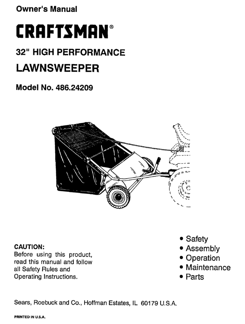
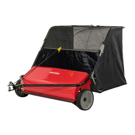
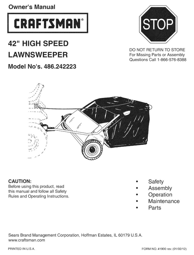
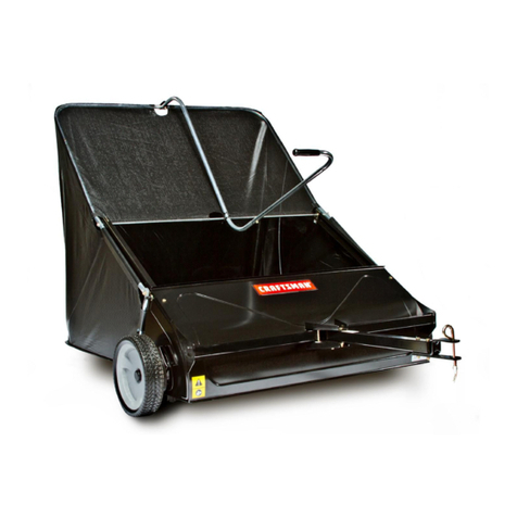
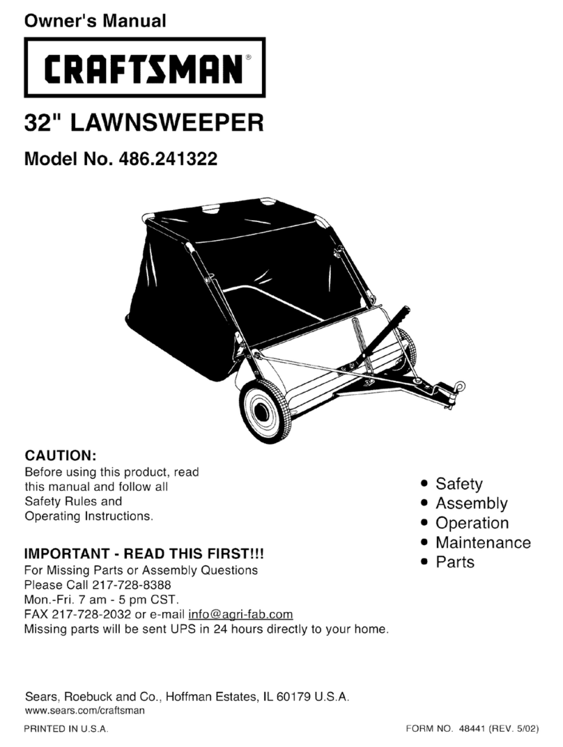
Craftsman 486.24223 User manual

Other Craftsman Lawn Sweeper manuals

Craftsman 486.24222 User manual

Craftsman

Craftsman 486.24222 User manual

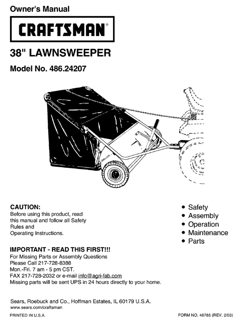
Craftsman 486.24207 User manual

Craftsman

Craftsman 486.24207 User manual

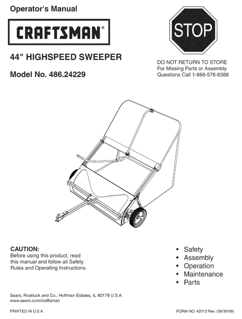
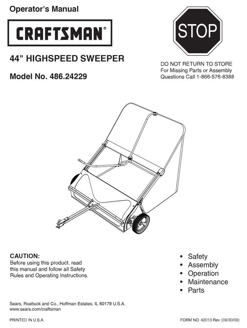
Craftsman 486.24229 User manual

Craftsman

Craftsman 486.24229 User manual

Craftsman 486.241320 User manual

Craftsman

Craftsman 486.241320 User manual

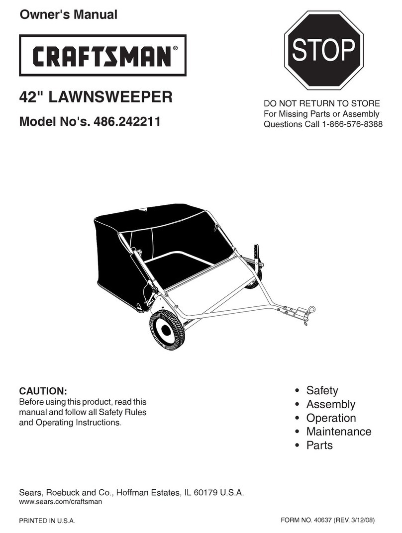
Craftsman 486.242211 User manual

Craftsman

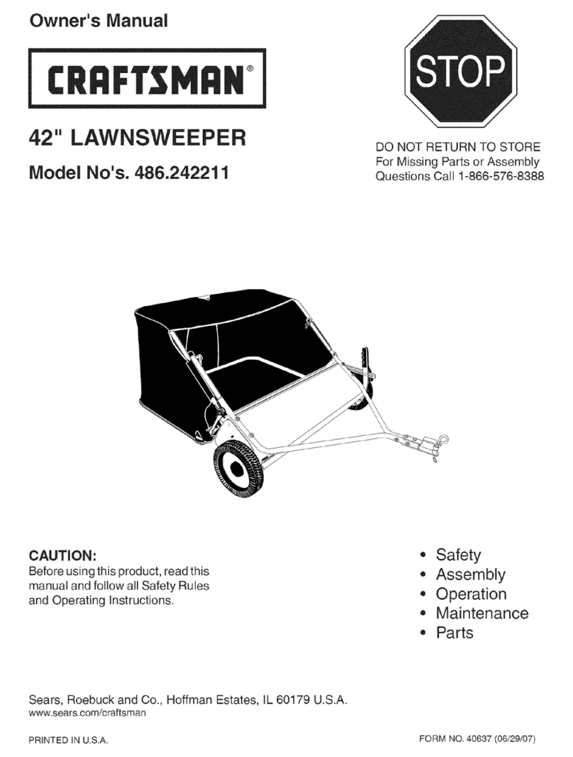
Craftsman 486.242211 User manual

Craftsman 486.24212 User manual

Craftsman

Craftsman 486.24212 User manual

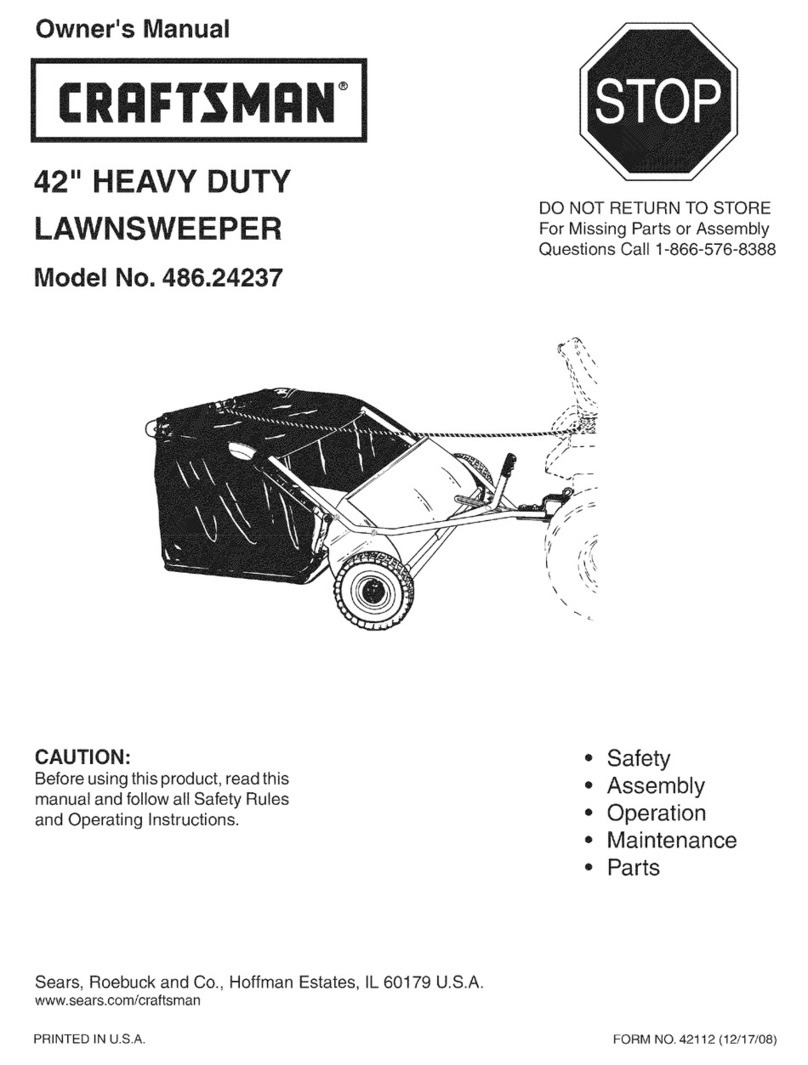
Craftsman 486.24237 User manual

Craftsman

Craftsman 486.24237 User manual

Craftsman 486.241321 User manual

Craftsman

Craftsman 486.241321 User manual

Craftsman 486.242112 User manual

Craftsman

Craftsman 486.242112 User manual

Craftsman 486.242231 User manual

Craftsman

Craftsman 486.242231 User manual

Craftsman 486.242221 User manual

Craftsman

Craftsman 486.242221 User manual

Craftsman 24222 - 42 in. High Speed Sweeper User manual

Craftsman

Craftsman 24222 - 42 in. High Speed Sweeper User manual

Craftsman 486.242223 User manual

Craftsman

Craftsman 486.242223 User manual

Craftsman 486.241322 User manual

Craftsman

Craftsman 486.241322 User manual

Craftsman 486.242223 User manual

Craftsman

Craftsman 486.242223 User manual

Craftsman 486.240383 User manual

Craftsman

Craftsman 486.240383 User manual

Craftsman 486.242291 User manual

Craftsman

Craftsman 486.242291 User manual

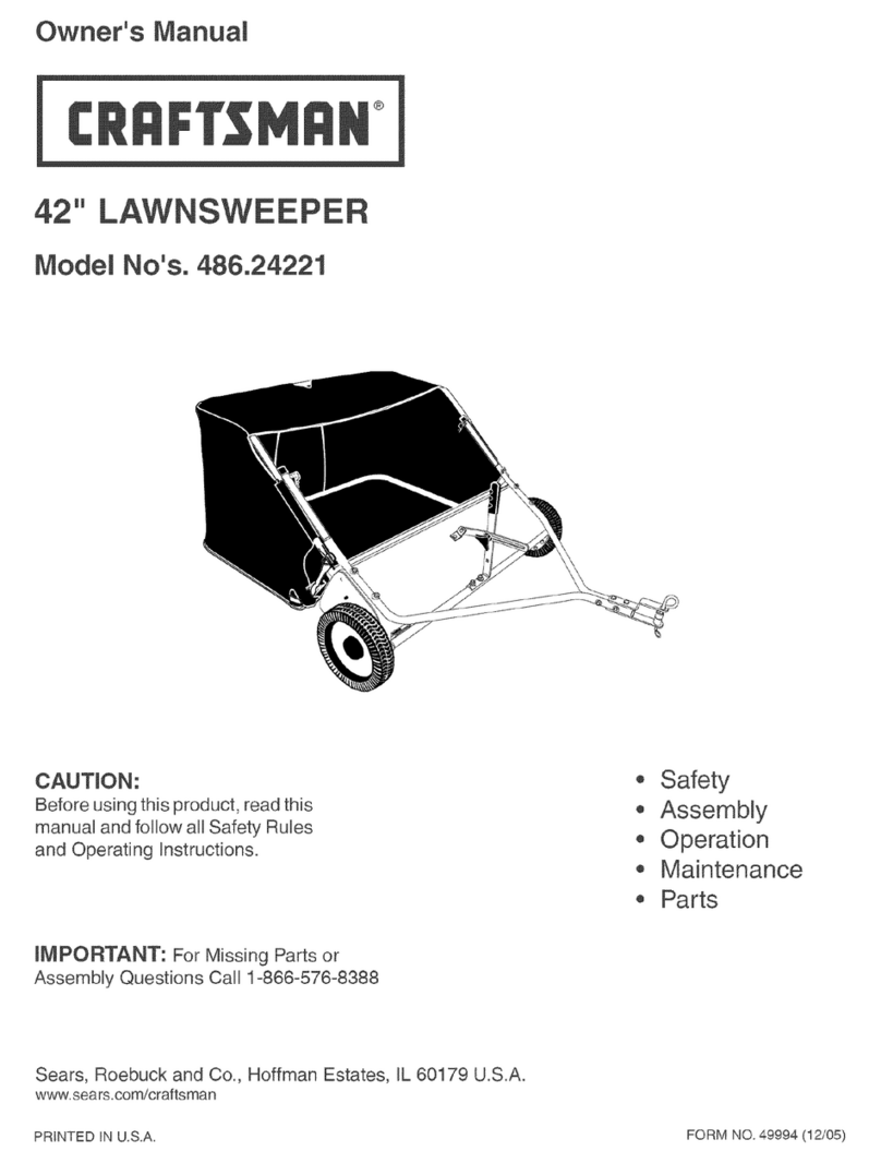
Craftsman 486.24221 User manual

Craftsman

Craftsman 486.24221 User manual

Craftsman 486.240362 User manual

Craftsman

Craftsman 486.240362 User manual

Craftsman 486.24029 User manual

Craftsman

Craftsman 486.24029 User manual

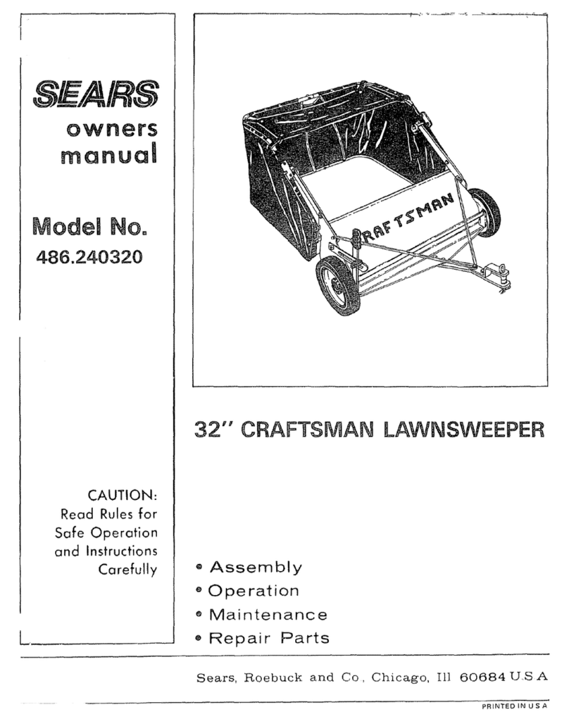
Craftsman 486.240320 User manual

Craftsman

Craftsman 486.240320 User manual

Craftsman 486.24207 User manual

Craftsman

Craftsman 486.24207 User manual

Craftsman 486.242211 User manual

Craftsman

Craftsman 486.242211 User manual

Craftsman 486.24229 User manual

Craftsman

Craftsman 486.24229 User manual

Popular Lawn Sweeper manuals by other brands

RedMax RedMax Sweeper EX-RMS Operator's manual

RedMax

RedMax RedMax Sweeper EX-RMS Operator's manual

Parker PV0110BSPH Operation service parts care

Parker

Parker PV0110BSPH Operation service parts care

MTD 19468-1 owner's guide

MTD

MTD 19468-1 owner's guide

BLACK DECKER LSWV36 instruction manual

BLACK DECKER

BLACK DECKER LSWV36 instruction manual

Kugelmann AMM Original operating instructions

Kugelmann

Kugelmann AMM Original operating instructions

HAKO Hako-Profi-Flipper instruction manual

HAKO

HAKO Hako-Profi-Flipper instruction manual

Tornado SWM 31/9 Operation & maintenance manual

Tornado

Tornado SWM 31/9 Operation & maintenance manual

Husqvarna 325L X Series Operator's manual

Husqvarna

Husqvarna 325L X Series Operator's manual

Windsor Sweepers owner's manual

Windsor

Windsor Sweepers owner's manual

Trynex Sweepex SWB-400 owner's manual

Trynex

Trynex Sweepex SWB-400 owner's manual

Kärcher KM 80 W P Operation manual

Kärcher

Kärcher KM 80 W P Operation manual

MID WEST PRODUCTS B-319SSNT Owner's manual and parts list

MID WEST PRODUCTS

MID WEST PRODUCTS B-319SSNT Owner's manual and parts list

Coopers 8814 instructions

Coopers

Coopers 8814 instructions

International 1A Operator's manual

International

International 1A Operator's manual

RedMax RMS-EX600 Operator's manual

RedMax

RedMax RMS-EX600 Operator's manual

AllFitHD AF-5026LS manual

AllFitHD

AllFitHD AF-5026LS manual

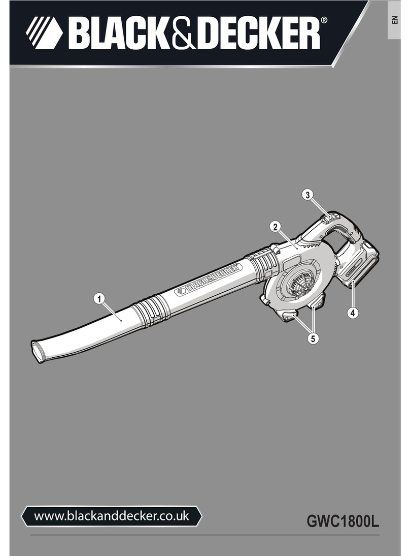
Black & Decker GWC1800L Original instructions

Black & Decker

Black & Decker GWC1800L Original instructions

Sanitaire SC6093A owner's guide

Sanitaire

Sanitaire SC6093A owner's guide

manuals.online logo
manuals.online logoBrands
  • About & Mission
  • Contact us
  • Privacy Policy
  • Terms and Conditions

Copyright 2025 Manuals.Online. All Rights Reserved.

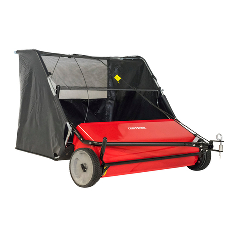
Owner's Manual
®
46" HiGH PERFORMANCE
LAWNSWEEPER
Model No. 486.24223
DO NOT RETURN TO STORE
For Missing Parts or Assembly
Questions Call 1-866-576-8388
\ \ X
CAUTION:
Before using this product, read this
manual and follow all Safety Rules
and Operating Instructions.
,, Safety
,, Assembly
,, Operation
,, Maintenance
,, Parts
Sears, Roebuck and Co., Hoffman Estates, IL 60179 U.S.A.
www.sears.com/craftsman
PRINTED IN U.S.A. FORM NO. 48742 (3/06)
Safety Rules .................................................................... 2
Carton Contents .............................................................. 3
Accessories and Attachments ......................................... 3
Full Size Hardware Chart ................................................ 4
Sweeper Assembly Instructions ...................................... 5
Hopper Assembly Instructions ......................................... 7
Operation ....................................................................... 11
Maintenance Schedule .................................................. 12
Storage .......................................................................... 12
Service and Adjustments ............................................... 13
Troubleshooting ............................................................. 13
Repair Parts Illustration ................................................. 14
Repair Parts List ............................................................ 15
Parts Ordering/Service ................................... Back Cover
ONE YEAR FULL WARRANTY
When operated and maintained according to the instructions supplied with it, if this Craftsman Lawnsweeper fails due to a
defect in material or workmanship within one year from the date of purchase, call 1-800-4-MY-HOME® to arrange for free
repair (or replacement if repair proves impossible)
If this product is used for commercial or rental purposes, this warranty applies for only 90 days from the date of purchase.
This warranty gives you specific legal rights, and you may also have other rights which vary from state to state.
Sears, Roebuck and Co., D817WA, Hoffman Estates, IL 60179
Any power equipment can cause injury if operated improperly or if the user does not understand how to operate the equipment.
Exercise caution at all times, when using power equipment.
1. Read the vehicle and sweeper owners manuals and
know how to operate your vehicle and sweeper before
using this sweeper attachment. Always instruct other
users before they operate the sweeper.
2. Do not permit children to operate sweeper.
3. Do not permit anyone to ride on sweeper.
4. Never attach the hopper rope to any part of your body
or clothing! Never hold onto the rope while towing the
sweeper! Attach the rope to the towing vehicle to keep
it away from wheels and rotating parts.
5. Operate the sweeper at reduced speed on rough
terrain, near ditches and on hillsides to prevent loss of
control.
6. Vehicle braking and stability may be affected with
the attachment of this sweeper. Do not fill sweeper
to maximum capacity without checking the capability
of the towing vehicle to safely pull and stop with the
sweeper attached. Stay off of steep slopes,
7. Stop and inspect vehicle and sweeper for damage
after striking an object. Repair any damage before
continuing operation.
8. Keep sweeper away from fire. Excessive heat can
damage the brushes and hopper bag and could cause
the bag and its contents to burn.
9. Before storing the sweeper, always empty the hopper
bag to avoid spontaneous combustion.
10. Follow maintenance and lubrication instructions as
outlined in the maintenance section of this manual.
Look for this symbol to point out important safety precautions. It means -- Attention!!
Become alert!! Your safety is involved.
The model and serial numbers will be found on a decal
attached to the lawnsweeper.
You should record both the serial number and the date of
purchase and keep in a safe place for future reference.
MODEL NUMBER:
SERIAL NUMBER:
DATE OF PURCHASE:
486.24223
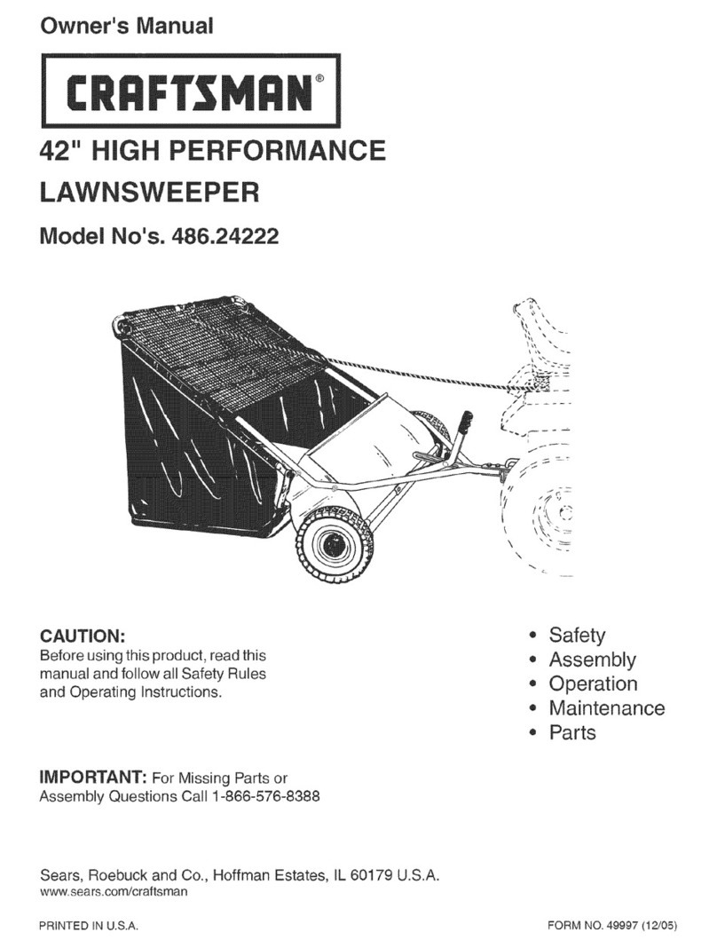
Theseaccessorieswereavailablewhentheunitwaspurchased.TheyarealsoavailableatmostSearsretailoutletsand
servicecenters.MostSearsstorescanorderrepairpartsforyouwhenyouprovidethemodelnumbersofyourtractorand
sweeper
!
The Front Mount Dethatcher, Model 486.24219 attaches |
to the lawn sweeper to help loosen and remove dead 1
grass and thatch from the lawn while sweeping.
CARTON CONTENTS (Loose Parts in Carton)
1. Sweeper Housing Assembly
2. Bag Arm Tube (2)
3. Hitch Tube, Left Hand (Marked 39L)
4. Hitch Bracket Assembly
5. Hitch Bracket, Bent
6. Height Adjustment Plate
7. Height Adjustment Handle
8. Hitch Tube, Right Hand (Marked 40R)
9. Rope
10. Hopper Bag
11. Rear Hopper Tube (2)
12. Upper Hopper Tube (2)
13. Lower Hopper Tube (2)
14. Hopper Bag Pivot Rod
15. Hopper Support Strap (2)
16. Bag Frame Strap
12
12
8
\
116
3

SHOWN FULL SiZE
/B
N
i
DJ F _!JG
, /
M
P
/
Q
s
/
NOT SHOWN FULL SiZE
T
/
Iv
w
/
REF.
A
B
C
D
E
F
G
H
I
J
K
L
QTY.
2
2
4
2
3
17
2
1
4
3
2
2
DESCRIPTION
Hex Bolt, 5/16-18 x 3" Lg.
Hex Bolt, 5/16-18 x 2-1/4" Lg.
Hex Bolt, 5/16-18 x 1-3/4" Lg.
Hex Bolt, 5/16-18 x 3/4"
Carriage Bolt, 5/16-18 x 1" Lg.
Nylock Nut, 5/16"
Palnut, 3/8"
Flat Washer, 3/8" Standard
Carriage Bolt, 5/16-18 x 3/4"
Spacer, .38" x .62" x .27"
Hitch Spacer, 3/4"
Clevis Pin, 3/8" x 1/2"
REE QT_
M 4
N 1
O 8
P 2
Q 1
R 2
S 4
T 1
U 1
V 4
W 1
DESCRIPTION
Clevis Pin, 1/4" x 1-1/8"
Hairpin Cotter, 1/8"
Hairpin Cotter, 3/32"
Clevis Pin, 1/4" x 1-3/4"
Cotter Pin, 1/8" x 3/4"
Vinyl Cap
Plastic Plug
Grip
Height Adjustment Pin
Hopper Clamp
Spring
TOOLS REQUIRED FOR ASSEMBLY
(1) Pliers
(1) Hammer
(2) 1/2" Open End or Box End Wrench
(1) 1/2" Socket Wrench (recommended)
STEP 4 = FASTEN HITCH TUBES
• Fasten the hitch tubes together using two hex bolts
(A) and nylock nuts (F). Do not tighten yet. See
figure 2.
10"
STEP 1 - REMOVE PARTS FROM CARTON
• To protect painted parts, lay them on cardboard or a
mat.
Remove the sweeper housing, the loose parts and the
hardware package from the carton. Lay out the parts
and hardware as shown on pages 3 and 4.
STEP 2-ASSEMBLE HITCH TUBES
The hitch tubes are stamped with a "39L" for the
left tube and a "40R" for the right tube. The sweeper
housing is marked with and "L" on the left side and an
"R" on the right side. See figure 1.
Hold the left hitch tube so that the end stamped with
"39L" is beside the left side of the sweeper and the
front end of the tube angles inward. Attach using two
hex bolts (C) and nylock nuts (F). Repeat for the right
hitch tube. Do not tighten yet. See figure 1.
STEP 3- REMOVE PLASTIC TIE
Remove the plastic tie that fastens the height
adjustment tube to the front of the sweeper housing.
See figure 1.
HEX BOLT (A)
NYLOCK NUT(F)
FIGURE 2
STEP 5 - MEASURE TRACTOR HITCH
Use the mark along the side of this page to measure
the height of the tractor hitch. The mark is 10" from
the bottom of the page. If the tractor hitch is less than
10" above the ground, go to STEP 6a. If the tractor
hitch is 10" or more above the ground, go to STEP 6b.
HEX BOLT (C)
1
PLASTIC TiE TUBE
/MARKED
"39L"
HITCH TUBE (L.H.)
FIGURE 1
STEP 6a - ASSEMBLE HITCH BRACKETS
If the tractor hitch is less than 10" above the ground,
place the bent hitch bracket underneath the hitch
tubes and place the hitch bracket assembly on top of
the hitch tubes. Insert two hex bolts (B) through the
brackets, with the rear hex bolt between the cross
bolts in the hitch tubes. Secure the hex bolts (B) with
two nylock nuts (F). See figure 3. Do not tighten yet.
Assemble the two spacers (K) onto the hitch pin and
secure the pin with the hairpin cotter (N). See figure 3.
HEX BOLTS (B)
" C2 t OKET
SPACERS(K)--------__
BENT HITCH----_ _
BRACKET
FIGURE 3
/
NYLOCK NUTS (F)
%_"_ HAIRPIN COTTER (N)
STEP 6b - ASSEMBLE HITCH BRACKETS
If the tractor hitch is 10" or more above the ground,
place the bent hitch bracket on top of the hitch tubes
and place the hitch bracket assembly underneath
the hitch tubes. Insert two hex bolts (B) through the
brackets, with the rear hex bolt between the cross
bolts in the hitch tubes. Secure the hex bolts (B) with
two nylock nuts (F). See figure 4. Do not tighten yet.
• Assemble the two spacers (K) onto the hitch pin and
secure the pin with the hairpin cotter (N). See figure 4.
HEX BOLTS (B)
HAIRPIN
COTTER(N)
BENT HITCH
BRACKET )_
SPACERS(K
HITCH BRACKET
FIGURE 4
I
NYLOCK NUTS(F)
STEP 7-TIGHTEN BOLTS
Tighten the four bolts in figure 1 that fasten the hitch
tubes to the sweeper housing. Next, tighten the two
bolts in figure 2 that fasten the ends of the hitch tubes
together. Finally, tighten the two bolts in figure 3 or 4
that fasten the hitch brackets to the hitch tubes.
STEP 8 - ATTACH HEIGHT ADJUSTMENT PLATE
Attach the height adjustment plate to the sweeper
housing using three carriage bolts (E), spacers (J)
(placed between plate and housing) and nylock nuts
(F). See figure 5.
Hint: Push the height adjustment tube down out of the way
to allow easier access to holes in sweeper housing.
Hint: Attach the bolts, spacers and nuts to one hole at a
time starting with the top hole to ease assembly.
CARRIAGE HEIGHT
BOLT (E)
SPACER (J)
NUT
HEIGHT
ADJUSTMENT
TUBE
FIGURE 5
STEP 9 - ATTACH HANDLE
Assemble the height adjustment handle to the height
adjust bracket at the front of the sweeper housing.
Use two hex bolts (D) and nylock nuts (F) to the
bracket. See figure 6.
• Assemble the grip (T) onto the end of the height
adjustment handle as shown in figure 6.
HEIGHT
ADJUSTMENT
HANDLE
HEX
FIGURE 6
HEmGHT
NYLOCK ADJUST
NUT (F) BRACKET
STEP 10 - ASSEMBLE HEIGHT ADJUSTMENT
PINPlace the height adjustment pin (U) into the height
adjust bracket. Assemble a spring (W) and washer (H)
onto the height adjustment pin (U) and then secure
them using a cotter pin (Q). See figure 7.
STEP 12 -ASSEMBLE LOWER TUBES
Fit the ends of the two lower hopper tubes into the
ends of a rear hopper tube. Align the holes in the ends
of the tubes and insert plastic plugs (S). See figure 9.
REAR
HOPPER
TUBE
PLASTIC PLUG (S)
LOWER
TUBE
FIGURE 9
FIGURE 7
STEP 13 - ASSEMBLE TUBES TO BAG
• Unfold the hopper bag, reversing the mesh wind
screen and then lay the bag out flat with the wind
screen on top.
Insert the ends of the assembled upper hopper tubes
down through the stitched sleeves in the sides of the
hopper bag and then slide the tubes back underneath
the wind screen. See figure 10.
STEP 11 - ASSEMBLE UPPER TUBES
Fit the ends of the two upper hopper tubes into the
ends of a rear hopper tube. Align the holes in the ends
of the tubes and insert plastic plugs (S). See figure 8.
REAR
HOPPER
TUBE
UPPER
HOPPER
TUBE FIGURE 10
STITCHED SLEEVE
UPPER
HOPPER
TUBE
HOPPER
BAG
BOTTOM
FIGURE 8 7
Place the assembled lower hopper tubes into the
bottom of the hopper bag and then slide the tubes to
the back of the bag. See figure 11.
Attach the ends of the lower hopper tubes to the
inside of the upper hopper tubes using two clevis pins
(L) inserted from the inside, and two hair cotter pins
(O). See figure 11.
UPPER HOPPER
Assemble the bag frame strap to the holes in the
lower hopper tubes using two clevis pins (M) and hair
cotter pins (O). See figure 13.
BAG FRAME STRAP
LOWER HOPPER TUBE
HAmR COTTER
PIN (O)\
t
CLEVIS PIN (L)
CLEVIS PiN (M
FIGURE 13
FIGURE 11
HOPPER BAG
BOTTOM
STEP 14 - ATTACH BAG BOTTOM
Insert the bag frame strap into the stitched sleeve at
the front edge of the bag bottom. See figure 12.
Fold the bag flaps around the lower hopper tubes and
attach to the bag bottom using the snaps. See figure
14.
BAG FRAME STRAP
STITCHED
SLEEVE
SNAP
FIGURE 14
STEP 15 - ASSEMBLE PIVOT ROD
• Attach the hopper support straps (end with smaller
hole) to the lower hopper tubes using a clevis pin (M)
and hair cotter pin (O) for each strap. See figure 15.
STEP 16 - ATTACH ROPE
• Secure the rope to the center of the upper rear hopper
tube as shown in figure 17. V
PIN (M)
</
_2_-._. HAIR COTTER
PIN (0) ..........
FIGURE 15
• Slide the end of the hopper bag pivot rod through one
upper hopper tube with hopper mount clamps. Place
the hopper support strap and a bag arm tube onto the
rod. Slide rod through the stitched sleeve at thefront
edge of the wind screen. Place the other bag arm tube
and hopper support strap onto the rod. Slide the end
of the rod through the other upper hopper tube with
hopper mount clamps. See figure 16.
Assemble two palnuts (G) by lightly tapping them onto
the ends of the pivot rod with a hammer. See figure 16.
Assemble a vinyl cap (R) onto each bag arm tube as
shown in figure 16.
HINT: To ease assembly of the palnuts, place the bag on
its side on a solid surface. With the bottom end of the pivot
rod against the surface, tap a palnut onto the top end of
the rod. Repeat for other end of rod.
CAP (R)
PALNUT (G)
/
HOPPER BAG
PIVOT ROD
FIGURE 17
STEP 17 - ATTACH HOPPER BAG
To attach the hopper bag to the sweeper, slide the
ends of the bag arm tubes into the ends of the hitch
tubes and secure with two clevis pins (P) and hairpin
cotters (O). See figure 18.
BAG ARM TUBE
CLEVIS PiN (P)
FIGURE 18
HOPPER SUPPORT STRAP
BAG ARM TUBE
FIGURE 16 9
ATTACHING SWEEPER HITCH TO TRACTOR
Place the tractor and sweeper on a flat level surface.
Set the sweeper height adjustment handle to about the
middle of its adjustment range.
Attach the sweeper hitch to the tractor hitch, arranging
the 3/4" spacers in one of six possible combinations as
shown in GROUP A and GROUP B diagrams below.
IMPORTANT: To obtain the best performance from your
sweeper, arrange the spacers so that the sweeper bag is
approximately level with the ground and approximately 5"
to 7" off the ground as shown in figure 19.
BRUSH HEIGHT ADJUSTED
APPROXIMATELYMID-WAY
APPROXIMATELY LEVEL
(5" TO 7" FROM SURFACE)
FIGURE 19
GROUP "A" = For vehicles with hitches
having 8" to 10" ground clearance. GROUP "B" -For vehicles with hitches
having 10" to 13" ground clearance.
\
\\ \\
\
\\ \\
\
HITCH BRACKET MOUNTED
ABOVE HITCHTUBES
HITCH BRACKET MOUNTED
BELOW HITCH TUBES
BLACK LINE IS TRACTOR HITCH BLACK LINE IS TRACTOR HITCH
10