moving the motor support assembly towards or away from
the cradle. Motor should be allowed to rest or hang
against the belt to obtain the automatic belt tightening
feature- and belt should be snug. If adjustment is cor-
rect, clamp the motor support in place by tightening the
two square head set screws (part S-1267, fig. 4).
ADJUSTING MOTOR MOUNT TENSION, Tension
is adjusted by tightening the nut (part S-1215, fig. 4)
against the steel washer (part S-1261) and the spring
washer (part 6423). Nut should be tightened just enough
to reduce motor vibration when saw is operating. Do
NOT tighten nut to alocked position, or the stud will be
sheared off when blade is raised or lowered. A sliding
action is necessary because mount changes position as
blade is raised or lowered. Operate the saw by hand to
make certain that the belt has proper tension and that
mount changes position as it should.
If saw is to be driven by a large frame motor that cannot
be mounted on the motor support assembly, mount the
motor on motor rails. Use a 1/2-inch wide belt with a
minimum length of 80 inches. Adjust the position of the
motor until belt clears all obstructions through all po-
sitions of the saw blade.
If saw is to be driven from a line shaft, use abelt at least
100 inches long.
PLACEMENT OF MITER GAGE- The miter gage as-
sembly (K, fig. 1) can be used in either one of the two
table grooves.
This saw is designed to be used with a3450 rpm motor.
Motor should be 3/4 hp (for light duty) or one hp (for
heavy duty)- in either an AC motor of arepulsion-
induction or capacitor type, or a compound-wound DC.
The motor shaft center siaould be approximately 4inches
above the bottom of the motor base. If this dimension
varies appreciably from 4inches, it may be necessary to
obtain abelt of adifferent length. If a 1750 rpm motor
with a 4-5/8-inch shaft center height is used, a 5-inch
motor pulley and a 46-inch belt must be purchased. If
the motor shaft center height varies greater or smaller
than the above dimension, a correspondingly greater or
smaller belt length should be used. _hese may be ordered
through any Sears Retail Store or Mail Order House.
CAUTION
Under no circumstances should a5-inch motor
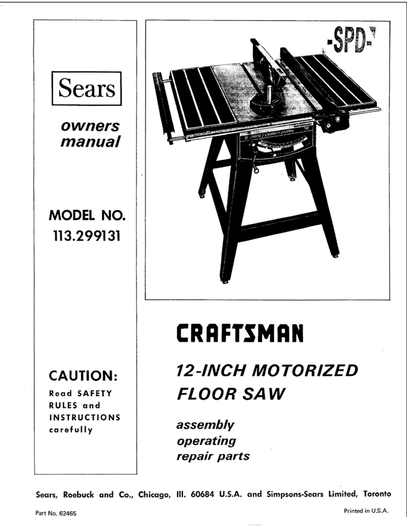
Figure 2
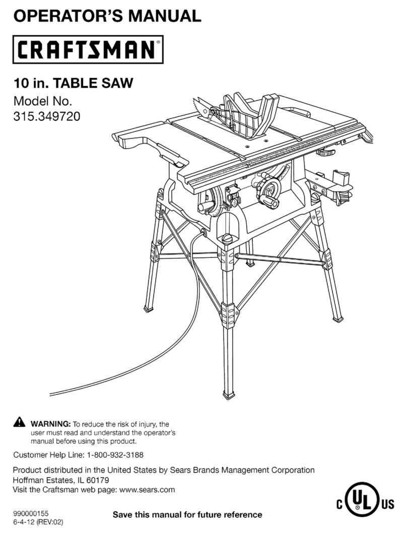
ELEVATION HAND WHEEL (A)- on the front of
the saw, controls elevation of the blade.
CLAMP SCREW HANDLE (D) on front of saw, locks
the tilt mechanism in any desired position. The
clamp screw handle operates like a socket wrench.
Tilt mechanism should always be locked before start-
ing work and should always be unlocked before
attempting to change the angle of tilt.
TILT HAND WHEEL (B) on left side of saw, con-
trois the angle of tilt. The saw blade can be tilted
from 0°to 45 °, as indicated on the TILT GAGE
(C). If the angle of cut (tilt) must be extremely_
accurate, the angle of the saw blade should be
checked with a protractor or with a board which is
known to be cut at the exact angle required.
RIP FENCE (E) -- is operated by pushing in the FENCE
KNOB (F) so that it engages apinion gear with
the teeth on RACK (H). Turning the knob (F),
after pushing it in, will cause the rip fence to move
accurately across the table. When the knob (F) is
pulled out to disengage pinion gear, the rip fence
can be moved across the table by hand. Keep the
saw table and rip fence clean. Dirt may prevent the
rip fence from obtaining proper alignment. Tapping
the fence lightly to assist the mechanism to find its
natural position, will help to maintain alignment of
the fence with the blade.
CAM CLAMP LEVER (G)m is used to clamp the rip
fence in place after it has been moved to the position
desired.
MITER GAGE (J) w is used in table grooves as a guide
for the workpiece when the fence is not used. The
angle of the gage can be adjusted by loosening
CLAMP KNOB (K) and positioning gage as indi-
pulley be used with a 3450 rpm motor. The saw
blade speed resulting from such apulley ratio cated by the dial and pointer on (J).
would be dangerous. Do not use a 2fi_-inch MITER GAGE STOP ROD (L)--can be adjusted in
motor pulley _Tith a 1750 rpm motor --_is will length by loosening WING NUT (M). TI_ rod is
not ive satisfactory saw erformance, useci as a positioning guide for the end of the work-
gPptece.
The ¸ their uses. See figure 2.
_3_
CAUTION
Under no circumstances sh_d a blade with a
diameter greater than 10 inches: be _ with
this saw.
